
Abstract
Processing of low grade ores for metal extraction leaves behind a huge mass of residue, which may be disposed by land filling. However, prior removal of toxic heavy metals is imperative to prevent ground water pollution. Electrokinetic remediation used for treating contaminated soils could be adapted for the removal of heavy metals from industrial residues. Preliminary electrokinetic cleaning experiments on dichromate residue showed the feasibility of removal of Cr(VI) from residue along with pH modification. From an initial concentration of 1758 mg kg−1, the concentration of Cr(VI) could be brought down to 615 mg kg−1, besides the drop in pH from 10·9 to 6·8 in 72 h. The residue thus can be a start-up material for other remediation processes such as phytoremediation.
Introduction
Depletion of rich ores has gradually led to the development of processes using low grade ores such as chromite overburden and manganese nodules for extracting metal values. Existing processes for extraction of metal values are also generating a huge amount of residues like ‘red mud’. It is almost impossible to utilise the huge mass of residue as a byproduct. Assuming about 1–3% of metal values for a low grade ore, after processing, the residue generated will be almost equal to the ore content processed. Land filling could be one effective method for disposing low grade ore residues. However, toxic heavy metals in the residues can be leached by rain water, which, in turn, can contaminate not only the ground water but also the crops grown on the soil by ground water irrigation. Consequently, cost effective technologies are needed to process these residues before they can be safely used as landfills.
Hydrometallurgical processing of residues using operations such as leaching and extraction could be an effective method for removing heavy metals from residues. Unfortunately, these processes may not be economical for treating large quantities of residue, more so if several contaminants are present. A possible, cost effective method for removing heavy metals could be electrokinetic remediation, which has been used extensively for remediating heavy metal contaminated soils (Page and Page, 2002; Yeung, 2011). All inorganic and organic contaminants that are soluble in water can be removed simultaneously from soil. A direct current, of the order of mA cm−2, is applied between a series of graphite electrode pairs positioned at regular intervals across contaminated soil. The graphite electrodes are placed inside chambers containing ‘conditioned’ water. Application of voltage/electric field results in the electrolysis of water in the electrode chambers and the simultaneous transport of contaminants towards either the anode or the cathode chambers, from where they are simply pumped out. The dominant mechanisms for transporting contaminant species are electromigration and electroosmosis. In electromigration, the ions move in response to the electric field; toxic cations such as Cu2+ are collected in the cathode chamber, while anionic species such as
 are collected in the anode chamber. Electroosmosis causes bulk motion of liquid within the pores of the soil, normally from the anode towards the cathode, taking the ions, irrespective of their polarity, along with it. Uncharged, water soluble organic components are also removed from soil by electroosmosis. Electroosmosis is only effective in fine grained soils with micrometre sized pores. On the other hand, electromigration is not a function of pore size. In addition to the transport of contaminants, H+ and OH− migrate towards the cathode and anode chambers respectively. Because of the higher mobility of H+, an acid front moves in the soil towards the cathode, the motion of the acid front being a function of the buffering capacity of the soil. Other implications of the presence of H+ and OH− are described elsewhere (Acar and Alshawabkeh, 1993). It may be pointed out that the efficacy of electrokinetic remediation is directly proportional to the degree of saturation of the contaminated soil.
The objective of the proposed investigation has been to explore the feasibility of electrokinetic remediation for removing heavy metals from industrial residues.
Experimental
Experiments were carried out with a residue obtained from a dichromate plant. The residue was grounded in a ball mill and sieved with −100 mesh and then compacted in a Perspex tube. The parameters of the residue compact are shown in Table 1.
Parameters used for electrokinetic residue treatment
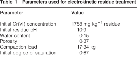
Figure 1 is a schematic diagram of the experimental set-up that is similar to the one described by Sanjay et al. (2003). Here, two threaded Perspex caps containing the graphite electrodes and electrolyte chambers were fitted to the ends of the tube containing the compacted residue. The graphite electrode contained holes for the flow of chamber fluids by electroosmosis. In order to support the soil, a filter cloth fixed to a ring was incorporated. A filter paper was placed between the filter cloth and the soil for preventing fine soil particles from entering the electrode chambers. In addition, the vents were provided in front of the electrodes, i.e. between the electrodes and soil, so as to remove the gases immediately after they are produced near the electrodes. Stainless steel electrodes were fitted along the length of the tube to measure the potential drop in different sections of the soil. Six dummy electrodes were fitted as shown in the figure, dividing the soil specimen to five sections. The sections are numbered from 1 to 5, with section 1 being beside the cathode and section 5 beside the anode.
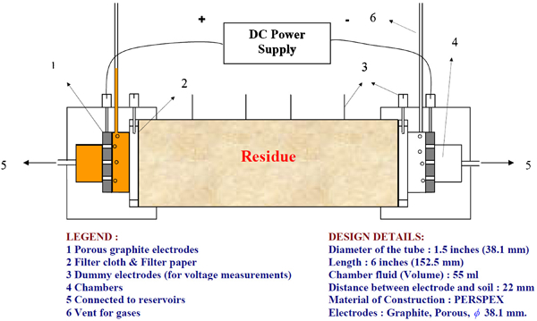
Schematic diagram of experimental set-up
The reservoirs and the electrolyte compartments were filled with double distilled water. The levels in the reservoirs were kept at the same level to avoid hydraulic gradient. Graphite electrodes were connected to a constant voltage direct current power supply and operated at a constant voltage of 25 V. During the course of the experiment, the electroosmotic flow from anode to cathode resulted in a decrease in the anode reservoir level and an increase in the cathode reservoir level. Levels in the reservoirs were intermittently adjusted to ensure that the difference in the electrolyte level never exceeded 0·01 m to eliminate flow due to hydraulic gradient. At regular time intervals: fluid samples from reservoirs and chambers were drawn for Cr(VI) and total Cr analysis; voltage drop in different sections of the soil was measured along with current; and volume in the reservoirs was noted. Cr(VI) was analysed colorimetrically in accordance with US-EPA method 7197A. Water analyser Spectroquent (model: NOVA 60) procured from Merck was used for Cr(VI) analysis. For pH of the residue, oven dried residue sample and double distilled water were taken in 1∶1 ratio (w/w), mixed thoroughly and centrifuged. The pH of the resulting liquid represented the residue pH (ASTM D4972).
Results and Discussion
Figure 2 is a schematic diagram of the kinetics of removal of Cr(VI) from the residue. More than 50% of Cr(VI) has been removed in ∼10 h. Thereafter, an additional 15% of Cr was removed in the next 68 h, after which the experiment was stopped.
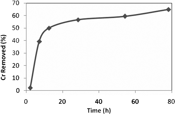
Kinetics of removal of Cr(VI) from dichromate residue
Cr(VI) accumulated in the anode chamber, which shows that the predominant transport mechanism of Cr in dichromate residue is migration. The mass balance at the end of the experiment showed that ∼26% of Cr(VI) remained in the residue, ∼65% was removed and the rest 9% chromium was unaccounted. The unaccounted Cr was probably adsorbed in soil or reduced to Cr(III). The pH measured after mixing all the sections subsequent to electrochemical cleaning was 6·8, which is lower by 4·1 than its initial value of 10·9.
The voltage profile across the residue compact is depicted in Fig. 3. Here it is seen that a steep potential gradient formed in section 5, but swiftly moved to section 4 after ∼10 h. The high voltage drop in section 4, a consequence of acid base neutralisation, reduces the effective driving force for both electromigration and electroosmosis and results in the drastic reduction in kinetics of Cr(VI) removal. The reasons for acid base neutralisation and methods to counter it and thereby increase both the kinetics and contaminant removal have been discussed by Sanjay (2007).
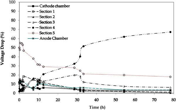
Potential drop profile in residue compact during electrokinetic remediation
The plot related to electroosmotic flow is shown in Fig. 4. It shows the total change in volume in the cathode and anode reservoirs as a function of time. Positive values indicate an increase in reservoir volume and vice versa. Because of electroosmosis, the volumes of the anode and cathode reservoirs are expected to decrease and increase respectively. The initial drop in the volume of the cathode reservoir is primarily due to water entering the cathode end of the soil due to hydrostatic pressure. It is interesting to note that after ∼12 h, the electroosmotic flowrate (given by the slope of the curve in Fig. 4) decreases significantly, which is a consequence of acid base neutralisation, and has been discussed by Manna et al. (2003).
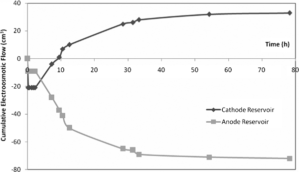
Electroosmotic flow during electrocleaning of dichromate residue
A fascinating aspect of the electroosmotic curve is the observation that the increase in the volume of the cathode reservoir is less than the decrease in the volume of the anode reservoir. Clearly, this means that electroosmotic flow also fills up the pores in the residue compact, thereby increasing its degree of saturation, which, in turn, increases the efficiency of electrokinetic remediation.
Clearly, the set-up of the type shown in Fig. 1 cannot be used to remediate large areas of contaminated residue. Large areas of contaminated residue can be processed in situ by placing electrodes at regular intervals. A typical laboratory set-up, used for remediating Cr(VI) contaminated soils or residues, which can be replicated over a large area, is shown in Fig. 5 (Ahmad, 2004; Kumar, 2004). The depth of remediation is not an issue and can be tackled by increasing the height of the electrode chambers.
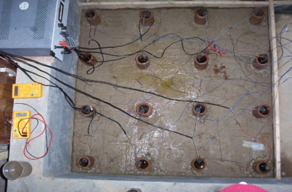
Laboratory set-up used for remediating Cr(VI) contaminated soil: electrode chambers are clay tubes filled with tap water and graphite rod electrodes; alternate rows of anode and cathode chambers are also shown
Conclusion
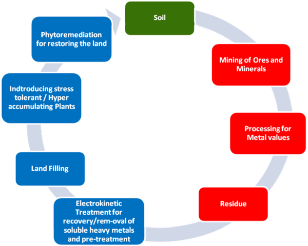
Limited experiments suggest that electrokinetic remediation could be a feasible method for removal of hazardous contaminants from ore residues, which could then be used for land filling. It is, however, possible that the entire contaminant mass may not be economically removed by electrokinetic remediation. A general framework for processing of ores and disposal of resulting residues with minimal adverse environmental impact is shown in Fig. 6.
General framework for processing of ores and disposal of residues with minimal environmental impact
Phytoremediation, on its own, has been proposed as an effective methodology for cleaning contaminated sites. However, it suffers from three major disadvantages with respect to electrokinetic remediation: relatively lower contaminant removal kinetics, requirement of conditioned soils and nutrients for plants, and remediation being restricted to the root depth. The fresh residue coming from any process generally has extreme pH (high alkaline or acidic) with high activity and the essential nutrients for phytoremediation may not be present. Hence, subjecting the residue by electrokinetic remediation can prepare the residue for phytoremediation. The motion of H+ and OH− can be manipulated to condition the residue to the right pH.3, 5 Moreover, electroosmosis can be used to transport the essential nutrients to the residue. The present study shows that through electrokinetic cleaning, pH can be modified to near neutral pH simultaneously along with removal of soluble heavy metals. More experiments are necessary to validate the proposed framework.
Footnotes
Acknowledgements
One of the authors wishes to thank the Director, Institute of Minerals and Materials Technology, Bhubaneswar and Council of Scientific and Industrial Research, New Delhi for the financial support.