
Abstract
Direct electrodeposition of ternary Mg–Li–La alloys on a molybdenum electrode from LiCl–KCl–MgCl2–LaCl3 melts at 943 K was investigated. Cyclic voltammograms showed that the underpotential deposition of lithium on predeposited Mg–La alloy leads to the formation of Mg–Li–La alloy. Chronopotentiometric measurements indicated that the codepositon of Mg, Li and La occurs at current densities more negative than −0·62 A cm−2. The microstructure of Mg–Li–La alloys was analysed by X-ray diffraction, optical micrograph and SEM. The X-ray diffraction analysis indicated that α+Mg17La2, α+β+Mg17La2 and β+LaMg3 Mg–Li–La alloys with different lithium and lanthanum contents were obtained via galvanostatic electrolysis with different concentrations of MgCl2. The results of SEM suggested that element La exists at grain boundaries to restrain the grain growth rate.
Introduction
Since Mg–Li alloys have low density and high strength to weight ratio, it is expected to be applied for using in a wide range of structural applications recently (Sanschagrin et al., 1996). However, poor formability and lower melting temperatures limit its wide applications. It is well known that addition of rare earth is effective in improving the mechanical properties of Mg–Li alloys (Liu et al., 2008). Many researchers have proved that the preparation of alloys by electrochemical methods has many advantages as compared with directly mixing of the metallic elements, such as energy saving and pollution decreasing. For example, several investigators (Iida et al., 2001; Groult et al., 2010) have investigated the electrochemical deposition of Co–Sn alloys and Sm–Ni alloys from LiCl–KCl melts. Polyakova et al. (2003) have reported the preparation of Nb–Ti alloy by electrochemical codeposition in NaCl–KCl–NaF melts. Using a relatively simple electrochemical method, our group has successfully deposited and diffused lithium to form Mg–Li alloys onto a magnesium cathode from LiCl–KCl melts at 693–783 K (Yan et al., 2008). Castrillejo et al. (2003a, b) have investigated the electrochemical properties of lanthanum in LiCl–KCl eutectic melt. The reduction process of La3+ is a single step and the rate of the process is diffusion controlled. Several authors performed studies of the electrodeposition of magnesium ions in CaCl2–NaCl, CaCl2–NaCl–KCl, eutectic LiCl–KCl and MgCl2–MgF2 melts (Børresen et al., 1997; Castrillejo et al., 1997; Martínez et al., 2004a, b).
On the basis of these existing research results, we propose a method for preparing Mg–Li–La alloys by an electrochemical process in molten salts. The aim of the present paper is to study the electrochemical codeposition behaviour of Mg, Li and La onto a molybdenum electrode in LiCl–KCl–MgCl2–LaCl3 melts by employing a series of electrochemical techniques and to prepare Mg–Li–La alloys by galvanostatic electrolysis.
Experimental
A mixture of LiCl–KCl (50∶50, w/w; analytical grade) was first dried under vacuum for >72 h at 573 K to remove excess water, and then melted in an alumina crucible placed in a quartz cell located in an electric furnace. The working temperature was measured with a thermocouple protected by an alumina tube inserted into the melt. Following this dehydration procedure, metal ion impurities in the melts were removed by preelectrolysis at −1·90 V(Ag/AgCl) for 4 h. All experiments were carried out under an argon atmosphere. Magnesium and lanthanum ions were introduced into the bath in the form of anhydrous MgCl2 and LaCl3 powder. In order to avoid LaOCl formation, HCl (g) was bubbled before determinations.
The electrochemical techniques were performed using the Im6eX electrochemical workstation (Zahner Co., Ltd, Kansas City, MO, USA) with the THALES 3·08 software package. Ag/AgCl was used as reference electrode, which was constituted by a silver wire (d = 1 mm) dipped into a Pyrex tube containing a solution of AgCl (1 wt-%) in the LiCl–KCl melts. The working electrodes consisted of molybdenum wire (d = 1 mm). The active electrode surface was determined after each experiment by measuring the immersion depth of the electrode. A spectral pure graphite rod (d = 6 mm) served as the counter electrode. All of the potentials were referred to as the Ag/AgCl couple.
The samples of Mg–Li–La alloys were prepared by galvanostatic electrolysis. After the electrolysis, all samples were washed in hexane (99·8% purity) in an ultrasonic bath, which hardly reacted with the Mg–Li–La alloys, to remove salts and stored in a glove box for analysis. These deposits were analysed by X-ray diffraction (XRD; X'Pert Pro; Philips Co., Ltd) using Cu Kα radiation at 40 kV and 40 mA. The samples for SEM (DFC320; Leica Microsystems) were mounted in thermosetting resins using a metallographic mounting press and then mechanically polished, and finally etched with a solution of 2 vol.-%HNO3 in alcohol. The etching time was 30–60 s. The microstructure and microzone chemical analyses were also measured using SEM, energy dispersive spectrometry (EDS) and electroprobe microanalysis (JSM-6480A; JEOL Co., Ltd). The specimen for SEM/EDS was polished and etched again using the former method and time. Each sample was dissolved in aqua regia (HNO3/HCl/H2O = 1∶3∶8, v/v). The solution was diluted and analysed using an inductively coupled plasma atomic emission spectrometer (ICP-AES; Thermo Elemental, IRIS Intrepid II XSP; Thermo Fisher Scientific, Boston, MA, USA) to determine Mg, Li and La contents of the deposits.
Results and Discussion
Cyclic voltammetry
Figure 1 shows the typical cyclic voltammograms obtained at a molybdenum electrode with different concentrations of MgCl2 and LaCl3 in LiCl–KCl melts at 943 K. From curve 1, apart from two cathodic/anodic signals (C/C’) corresponding to the reduction and oxidation of metal Li respectively, the redox system (A/A’) is ascribed to the deposition and dissolution of metal La with the addition of 2·2 wt-%LaCl3. The potential range of values is in agreement with the result obtained by Castrillejo et al. (2003a, b). After the addition of 0·5 wt-%MgCl2 (curve 2), peak B in the negative going scan is ascribed to the formation of Mg, because the deposition potential of Mg ions is more positive than that of La ions in a chloride system (Yang et al., 2005). Peak B’ in the positive going scan corresponds to the dissolution of deposited Mg. In curve 3, lithium commenced deposition at more positive potential on the substrate precovered by magnesium and lanthanum; the current increased sharply which resulted in the less obvious peak A caused by lanthanum deposition. According to the binary phase diagram of Mg–La system, different intermetallic compounds can be formed in Mg–La system (Guo and Du, 2004). However, no significant current resulted from the deposition of La on the substrate precovered by Mg was observed. Therefore, cyclic voltammetry at lower scan rates was attempted to further investigate the electrochemical formation of Mg–Li–La alloys (Fig. 2). A clear cathodic peak D and the corresponding anodic peak D’ were observed, suggesting that the underpotential deposition of lanthanum on predeposited magnesium leads to the formation of Mg–La alloys.
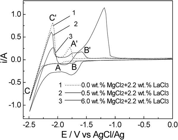
Cyclic voltammograms for molybdenum electrode in LiCl–KCl melts containing different MgCl2 and LaCl3 concentrations at 943 K: scan rate is 0·1 V s−1
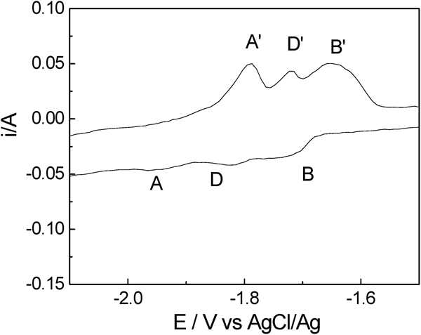
Cyclic voltammograms for molybdenum electrode in LiCl–KCl melts containing 2·2 wt-%LaCl3 and 0·5 wt-%MgCl2 at 943 K: scan rate is 0·025 V s−1
Chronopotentiometry
A chronopotentiometric experiment was carried out to further study the formation of Mg–Li–La alloys. Figure 3 presents the chronopotentiograms measured on a molybdenum electrode in LiCl–KCl–MgCl2 (6·0 wt-%) melts containing 2·2 wt-%LaCl3 at different current intensities. At a cathodic current more negative than −70 mA (current density: −0·21 A cm−2), the potential plateau T1 is associated with the reduction of magnesium ions to the corresponding Mg metal. Up to a current of −100 mA (current density −0·31 A cm−2), the second potential plateau T2 indicating that La(III) starts to be reduced was observed. At this current intensity, codeposition of Mg and La occurs. When the current reaches −300 mA (−0·93 A cm−2), a third plateau T3 appears. This plateau is caused by a reduction of lithium ions. At this current intensity, codeposition of Mg, Li and La occurs. It is obvious that the potential ranges for deposition of Mg, Li and La are the same as those observed in the cyclic voltammograms in the section on ‘Cyclic voltammetry’.
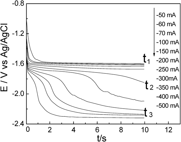
Chronopotentiograms at different current intensities for molybdenum electrode in LiCl–KCl melts containing 2·2 wt-%LaCl3 and 6·0 wt-%MgCl2 at 943 K
Galvanostatic electrolysis and characterisation of deposits
Based on the results obtained by cyclic voltammetrys and chronopotentiometrys, codeposited samples were prepared by galvanostatic electrolysis at −6·21 A cm−2 for 2 h using molybdenum electrodes in a molten LiCl–KCl–MgCl2–LaCl3 system at 943 K.
Figure 4 shows the typical XRD patterns with α+Mg17La2, α+β+Mg17La2 and β+LaMg3 Mg–Li–La alloy phases. In sample a, most of strong peaks are identified from α phase, while some of the weak peaks are from the crystal Mg17La2 phase. The presence of strong β phase diffraction peak with small amounts of α phase was shown in sample b when the concentrations of MgCl2 decreased to 7·5 wt-%. A new LaMg3 phase occurs in pattern c when the concentration of MgCl2 is 6·0 wt-% in LiCl–KCl–LaCl3 (2·2 wt-%) melts. The phenomenon is most likely due to a high lithium content in this Mg–Li–La alloy. Moreover, in patterns a–c, the lithium contents of Mg–Li–La alloys increase (from α, α+β to β phase) with the decrease in MgCl2 concentrations in the LiCl–KCl–LaCl3 (2·2 wt-%) melts at constant current intensity. Based on these results, we conclude that the variation in phases of Mg–Li–La alloys depends on the change in MgCl2 concentrations.
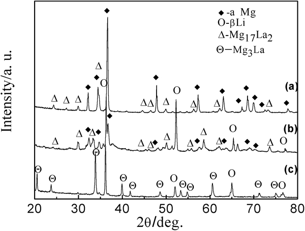
X-ray diffraction patterns of deposits obtained by galvanostatic electrolysis on Mo electrodes in LiCl–KCl–LaCl3 (2·2 wt-%) melts containing a 9·0 wt-%MgCl2, b 7·5 wt-%MgCl2 and c 6·0 wt-%MgCl2
The optical microstructure of the samples by galvanostatic electrolysis from LiCl–KCl–MgCl2 (9·0 wt-%) melts containing 1·2 and 2·2 wt-%LaCl3 is presented in Fig. 5. From Fig. 5, with more addition of LaCl3, the grain size becomes smaller due to the higher concentration of La in the Mg–Li–La. Based on the binary phase diagram of Mg–La system (Guo and Du, 2004), La, as a surface active element with its diffusion coefficient of <1, acts with Mg to form different intermetallic compounds. During the solidification process, Mg–La compounds mainly distribute in the grain boundary area, thus the grain growth is inhibited and the number of nuclei is increased.
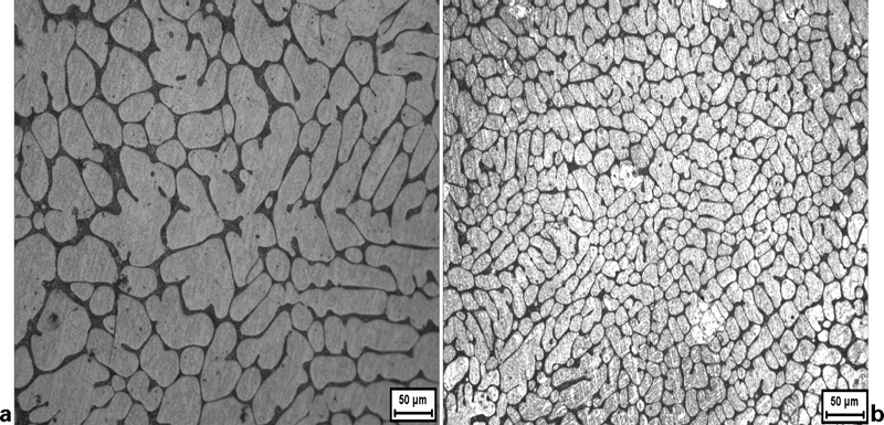
Optical micrographs of Mg–Li–La alloys by codeposition from LiCl–KCl–MgCl2 (9·0 wt-%) melts containing a 1·2 wt-%LaCl3 and b 2·2 wt-%LaCl3
To examine the uniformity of elements of Mg and La distributed in the Mg–Li–La alloys, a mapping analysis of the elements was employed. Figure 6 shows an SEM and EDS mapping analysis of the Mg–Li–La alloy by galvanostatic electrolysis from LiCl–KCl–LaCl3 (2·2 wt-%) melts containing 9·0 wt-%MgCl2. The black zone in the SEM corresponds to the bright matrix in the optical micrograph. The element Mg distributes homogeneously throughout the Mg–Li–La alloy, as shown in Fig. 6b. However, La distribution is not uniform and mainly disperses along the grain boundaries (Fig. 6c). Because windows in front of the Si (Li) detector can absorb low energy X-rays, EDS detectors cannot detect the presence of elements with an atomic number <4, meaning that EDS cannot detect Li, we carried out ICP. From the results of the ICP analyses, chemical compositions of Mg–Li–La alloys used for the XRD analysis are identified as Mg–2·45Li–2·98La (pattern a), Mg–13·52Li–5·89La (pattern b) and Mg–20·23Li–6·45La alloy (pattern c) respectively. Under galvanostatic electrolysis, the lower the MgCl2 concentration in the LiCl–KCl melts containing 2·2 wt-%LaCl3 at 2 A (a constant applied current) for 2 h, the higher the lithium content of the Mg–Li–La alloys.
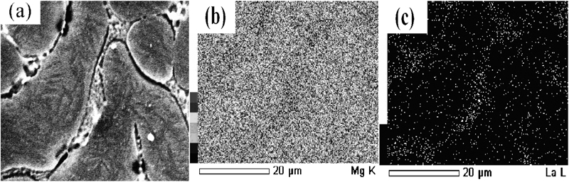
Mapping analysis (SEM and EDS) of Mg–Li–La alloys by galvanostatic electrolysis from LiCl–KCl–LaCl3 (2·2 wt-%) melts containing 9·0 wt-%MgCl2: a SEM; b area analysis using Mg Kα; c area analysis using La Kα
Conclusion
The electrochemical codeposition behaviour of Mg, Li and La on Mo electrodes in LiCl–KCl (50∶50, w/w) melts containing different concentrations of MgCl2 and LaCl3 was investigated at 943 K. According to the studies of codeposition conditions, Mg–Li–La alloys can be directly prepared via codeposition of Mg, Li and La on inert electrodes from LiCl–KCl–MgCl2–LaCl3 melts. Typical α+Mg17La2, α+β+Mg17La2 and β+LaMg3 phases of Mg–Li–La alloys with different lithium and manganese contents were obtained by galvanostatic electrolysis on molybdenum electrodes at a cathodic current density of 6·21 A cm−2 for 2 h at 943 K. Under galvanostatic electrolysis, the lower the MgCl2 concentration in the LiCl–KCl melts with equivalent LaCl3 concentration at a constant current intensity, the higher the lithium content of Mg–Li–La alloys. The EDS results showed that enough La atoms concentrate at the grain boundaries to react with Mg to form compound. Direct preparation of Mg–Li–La alloys by electrolysis using MgCl2, LiCl and LaCl3 as raw materials could revolutionise industrial production of Mg–Li–La alloys.
Footnotes
Acknowledgements
This work was financially supported by the National 863 Project of the Ministry of Science and Technology of China (2009AA050702), the National Nature Science Foundation of China (50871033) and the Fundamental Research funds for the Central Universities (HEUCF101002). The authors are grateful to professors Tom Mann, Jun Wang and Minghui Ding for their technical assistance and useful suggestions.