
Abstract
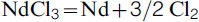
The present paper deals with the feasibility of the neodymium recovery from spent Nd–Fe–B magnets using molten salt electrodeposition method. The salt bath consisted of a mixture of LiCl–KCl–NaCl corresponding to the eutectic composition. The experimental set-up with its salient features is presented. AlCl3 was used as flux and graphite rods dipped in the salt bath served as electrodes. The voltage for the electrolysis was chosen on the basis of the decomposition potential of NdCl3. The reaction sequence can be described as

Iron-free neodymium deposition could be carried out successfully. In view of the proximity of the electrode potentials, the co-deposition of the aluminium and neodymium was observed to occur at the cathode, as revealed by SEM/EDS and XRD analyses of the electrodeposit.
Introduction
Rare earth elements are used in diverse industrial applications as well as in advanced military technologies because of their magnetic and conductive properties ( Velu and Reddy, 2005 ; Levkowitz, 2010 ). The basic composition of the neodymium magnet is generally Fe14Nd2B. Since the development of this permanent magnet with extremely strong magnetic power in 1980, the production volume of this magnet has increased substantially and is about 50 000 tons per year in the world ( Okabe et al., 2003 ). Having superior magnetic properties, neodymium is predicted to dominate the future magnetic material industry along with dysprosium ( Rampin et al., 2010 ; Coey, 2002 ).
Neodymium always coexists with other rare earth metals in natural ores (bastnasite and monazite) and it is the second largest abundant element among the lanthanides. Effective recycling process is needed to conserve the resources as the demand is increasing ( Takeda et al., 2006 ). International concerns have been raised on the supply shortages of rare earth elements since China the largest producer of rare earths has reduced the export of these elements recently, while, on the other hand, global demand for these materials has increased over last years.
During the manufacturing process of the neodymium magnets, about 50% of the charged neodymium is disposed as scrap, containing sludge powder which is the product of the machining step and also ‘off-spec’ products which have more oxygen impurity than the required specification. An effective process of neodymium scrap recovery is a major concern since most developed countries import their neodymium requirements ( Okabe et al., 2003 ; Takeda et al., 2006 ).
Hydrometallurgical operations for the extraction of rare earth compounds and separating them lead to the generation of huge amounts of waste water which pose a serious environmental problem. Furthermore, aqueous processing is generally slow. Extraction and refining of many reactive metals such as lanthanides and actinides by molten salt processing is attractive as other methods are not techno-economically feasible because of their thermodynamic or kinetic constraints. Number of active metals such as aluminium, magnesium, sodium and potassium are produced by molten salt reduction or electrolysis, in general because of the higher efficiency, lower energy consumption, no limitation due to H2 evolution and higher purity of the deposits ( Mishra and Olson, 2005 ; Han et al., 2011 ; Castrillejo et al., 2005a , 2005b ). Chloride melts are mostly used for different applications since, as compared to fluorides; they are less expensive, less corrosive and also have lower melting temperatures ( Han et al., 2011 ; Ito and Nohira, 2000 ).
Commercial rare earth magnets are usually coated by Ni and Al and elements such as Co, Dy and Al are used as additive elements in the neodymium magnet ( Uda, 2002 ). Among the fission products, neodymium, which has larger neutron capture cross-section, is one of the major elements and is desired to be removed in the chemical processing ( Fukasawa et al., 2011a , 2011b ).
In the present work, the salt extraction process, patented by Seetharaman and Grinder (2010) , is used for the recovery of Nd from Nd–Fe–B spent magnet. The salt extraction process is based on the recovery of metals from sources such as metallurgical slag, metal scrap, silicate-based ores and dust. This process has led to significant achievements in the metal extraction. Ge et al. (2010) have used the process for the first time to extract chromium from high-alloy steelmaking slags. Nearly 90% of chromium could be recovered. The same experiment was repeated by Khalaghi et al. (2012) with aluminium liquid as anode to confirm the results. The process was also used for recovery of Cu from chalcopyrite concentrate containing 26% copper ( Ge and Seetharaman, 2010 ). Recovery of lead from spent CRT glass was also performed which lead to investigations towards total recovery of Pb from old TV sets ( Teng et al., 2013 ). This process has been demonstrated in the present laboratory to be suitable for extraction of metal values in the molten salt system.
Earlier work
Electrochemical behaviour of neodymium in molten salt has been studied by number of researchers. Shirayama and Okabe (2009) used MgCl2 as the extracting agent and proposed that NdCl3 and DyCl2 are the stable phases under Mg/MgCl2 equilibrium. Hamel and Chamelot (2004) have proposed LiF–CaF2 binary mixture as a solvent to recover neodymium as pure metal on an inert cathode by electrowinning. Fukasawa et al. (2011a , 2011b) have studied the stability of Nd(III) complex in molten chlorides and proposed that the reduction process of Nd(III) to Nd(0) happens in two steps in LiCl–CaCl2 and LiCl–BaCl2 melts. The neodymium electrochemical behaviour has been also studied in LiCl–KCl, NaCl–CaCl2 and LiCl–CaCl2 by Yamana et al. (2006) , Castrillejo et al. (2003) , and Fukasawa et al. (2011a , 2011b) .
Velu and Reddy (2005)
have investigated the neodymium electrowinning from NdF3 with calcium, using CaCl2 as flux

They have achieved a yield of 97% by using graphite rod as anode and iron as cathode in this process and the temperature was above 1297 K (melting point of Nd) which may cause re-dissolution of Nd as NdCl3 and reduce the current efficiency. They have proposed that co-deposition of Fe with neodymium allows the process to be operated at lower temperatures. Chambers and Murphy (1989) had used a similar technique with Mg–Zn and Mg–Cd molten cathodes in NdCl3–KCl electrolyte to electrowin neodymium metal as an alloy in molten cathode, which was further purified by vacuum distillation.
Electrochemical behaviour of Dy, Er, Gd, Pr, and Ho on Al electrode in the eutectic LiCl–KCl has been investigated by Castrillejo et al. (2005a , 2005b , 2006a , 2006b ) to produce corresponding Al-based alloys. Gibilaro et al. (2008 , 2009a , 2009b) studied the co-reduction of aluminium and lanthanides in molten fluorides. Tsuda et al. (2003 , 2004a , 2004b) investigated a series of Al-based alloys by co-deposition from the molten salts of aluminium chloride-1-ethyl-3-methylimidazolium chloride. Han et al. (2011) studied the recovery of La by using AlCl3 and AlF3, for the metal electrodeposition on W and Mo cathodes.
Thermodynamic considerations
In the first step of the application of the salt extraction process for Nd extraction, the choice of fluxing agent is of high importance to enable an efficient dissolution of the metal in the molten salt phase. Earlier works in the present laboratory on the extraction of Fe and Cr from EAF slags and chromite ore have shown AlCl3 as a powerful chlorinating agent ( Ge et al., 2010 ). In the present work, AlCl3 is used as the flux to enable the dissolution of the magnet material into the salt bath. The metal chloride, which is formed as the result of chemical reaction between the metal in magnet and AlCl3, is subsequently subjected to electrolysis in order to be deposited on the cathode.
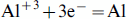
From computed Ellingham diagram for the formation of Nd and Dy chlorides using the equilibrium module in the FactSage software (FactSage 6·1), it is found that these elements can be selectively extracted, directly from magnet as chlorides, while Fe in the magnet is not chlorinated. The Gibbs energy formation of the different chlorides (Nd, Fe, Al and B) showed that only neodymium trichloride is more stable than AlCl3 in the case of the system containing AlCl3 and Nd2Fe14B at 1073 K. This confirms the formation of NdCl3, while FeCl3 and FeCl2 formation would be negligible. The Gibbs energies of the corresponding reactions are
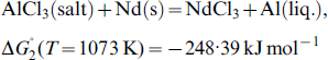
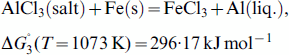
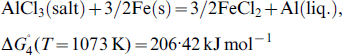
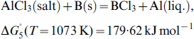
This provides the theoretical basis for the present experimental trials. It can be concluded that neodymium trichloride is formed as the result of reaction between Nd and AlCl3 whereas the formation of iron chloride is not favoured. It is to be noted that the above calculations are valid for pure substances at their standard states at the specified temperature. The activity values of chlorides would change because of the dissolution in the salt bath. Similarly, the activities of Nd and Fe would be lower in the magnetic alloy. The activity of neodymium in the Fe–Nd–B system at 973 and 1273 K was calculated by Uda (2002) . This author has used the thermodynamic data which was assessed by Hallemans et al. (1995) and found that all the neodymium in Fe14Nd2B can be dissolved in the molten chloride phase at the fixed chemical potential of Fe/FeCl2 equilibrium.
With regard to the Gibbs energies of different metals from a chloride bath, the decomposition potentials of neodymium trichloride as well as the alkali chlorides are calculated using FactSage (FactSage 6·1) and presented in Fig. 1. In this figure, it can be seen that the decomposition voltage for NdCl3 at 1073 K (800°C) is 2·6 V.
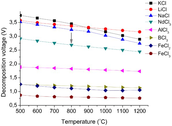
Calculated decomposition voltage as a function of temperature for all the chlorides formed by the dissolution of Nd–Fe–B alloys in LiCl–KCl–NaCl–AlCl3 molten salt bath
The chemical potential of chlorine in Nd/NdCl2 equilibrium is considerably lower than that of Fe/FeCl2, meaning that neodymium can get chlorinated without any chlorination of iron. Hence, in an electrolytic process, it will be optimum to keep the electrochemical potential of the system close to that of NdCl3 ( Uda, 2002 ).
The charge transfer is generally fast in the molten salt electrolyte and the cathodic deposition is generally diffusion-controlled (
Li and Bjerrum, 2002
). The overpotential, which causes deviation from the theoretical cell potential due to any kinetic limitation caused by electrode reactions and mass transport, is defined as (
Hamann et al., 2007
)
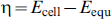
The standard electrochemical potential of Nd(III)/Nd(0) in LiCl–KCl eutectic mixture, determined experimentally by Castrillejo et al. (2003) , shows that the voltage changes from −3·151 to −3·055 V as the electrolysis temperature increases from 673 to 823 K. In the present work, a voltage of 3·4 V was applied for the electrodecomposition of NdCl3, considering the overpotential for the NdCl3 decomposition as 0·8 V.
Materials and experiments
The electrolyte consists of the eutectic composition of the salts LiCl, KCl and NaCl (E. Merck, Darmstadt, Germany; 99·5%). In all, 55 mol-% LiCl, 35 mol-% KCl and 10 mol-% NaCl were mixed together carefully and the mixture was dried at 383 K for at least 24 h. Neodymium magnets were used as Nd source. The magnet rings with the diameter of 3·5 mm were crushed into small fractions to enable easy dissolution of the magnet into the salt bath. Chemical composition of the magnets was analysed using scanning electron microscopy (SEM) equipped with an energy dispersive spectroscopy (EDS) probe to indicate the magnet composition. The results confirmed the iron to neodymium molar ratio as 14: 2 corresponding to the composition of the magnet Nd2Fe14B (boron being a light element could not be detected in the EDS analysis). Aluminium chloride (E. Merck, Darmstadt, Germany) was used as the flux. Alumina crucibles (99·5%, 40 mm o.d., 36 mm i.d., 60 mm height) (supplied by Keranova AB, Sweden) were used as the containers for the electrolytic cells. These were kept at 383 K for at least 24 h to remove any adsorbed moisture. The salt mixture along with the alumina crucible was heated up to 1073 K in a vertical furnace under an inert argon gas (ICP 5·0, AGA gas AB, Sweden) atmosphere, dehydrated by passing through silica gel.
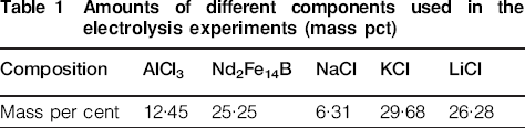
A number of experiments had been carried out with various flux/salt compositions (15–20–25 mass pct), as well as in different temperatures (1023–1113 K) and different electrolysis durations (from 5 to 11 h). As optimum factors, flux/neodymium ratio was chosen as 2: 1 (molar fraction) and flux/salt ratio was 20 (mass pct). Optimum temperature was chosen to be 1073 K and electrolysis duration of 6 h was considered as sufficient time. The optimum factors were chosen based on the neodymium extraction efficiency. Amounts of the various chemicals and the magnetic scrap used in the electrolysis experiments are presented in Table 1.
Amounts of different components used in the electrolysis experiments (mass pct)
The electrodes consisted of graphite rods. These were held 3–5 cm above the salt melt during the heating and served also as oxygen getters. The electrodes were dipped into the salt bath after the temperature reached 1073 K and electrolysis was started under a constant voltage of 3·4 V on the basis of the decomposition potential of NdCl3 and earlier experiences in the present laboratory using a similar approach with respect to other metals. A schematic diagram of the set-up is shown in Fig. 2. The voltage was supplied by a DC power supply (hp, Hewlett, 6632A). The electrolysis lasted 6 h. The cell was cooled down under argon atmosphere. After the experiment, the deposited layer on cathode was scraped out and was crushed. Some parts of the sample were analysed by SEM/EDS in order to observe the morphology as well as the composition of the elements. Wavelength Dispersive Spectroscopy (WDS, Jeol 7000F FEG-SEM) had been used to investigate the presence of boron in the samples. The phases in the sample from the deposited product on the cathode were also identified using X-ray diffraction (XRD) analysis.
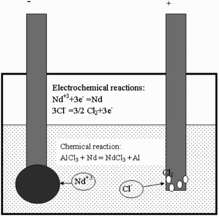
Schematic diagram of the set-up
Results
Four experiments were performed on the electrowinning of neodymium from neodymium magnet at 1073 K. The change of current density as a function of time during electrolysis is presented in Fig. 3. Current density was found to decrease from 6·37 to 4·78 A cm−2 during the 6 h of the experiment indicating a corresponding decrease in the deposition rate.
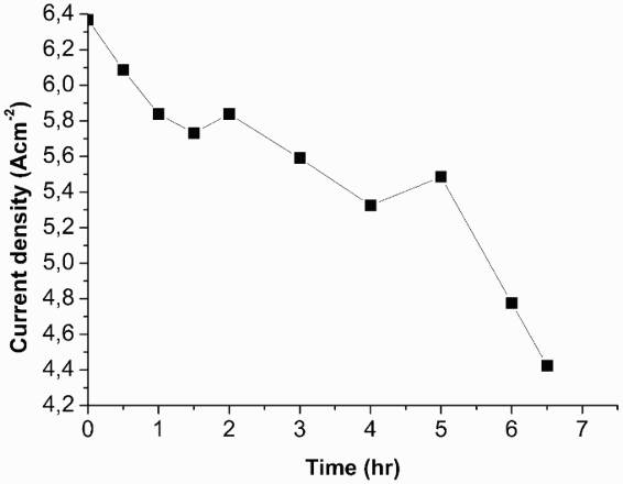
Changes of current density with time at the constant voltage of 3·4 V during 6 h of experiment
SEM analysis of the Salt bath
One experiment was carried out to examine the feasibility of the formation of neodymium trichloride. No electrolysis was carried out afterwards. In the dissolution process, the formation of neodymium trichloride in the salt bath was confirmed by the EDS mapping analysis of the sample from the salt bath bulk, which is shown in Fig. 4. From these images, it can be seen that neodymium and chlorine are distributed in the same areas, showing the formation of neodymium trichloride. It is also seen that aluminium and iron are distributed in the same area which confirms the dissolution of the magnet in the salt bath. The EDS results of same samples confirm the presence of Fe associated with Al in metallic form in the same part of the sample and the ratio between them correspond approximately to Al3Fe. The existence of such an intermetallic phase is confirmed by Al–Fe phase diagram. This indicates that Fe is retained by Al released as a result of the reaction between AlCl3 and Nd.
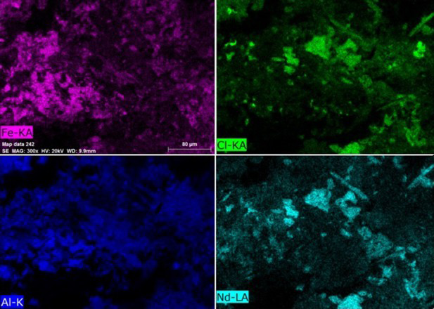
Surface distribution of Fe–Cl–Al–Nd elements on the sample from the bulk of the salt bath. Dissolution at T = 1073 K for 6 h
SEM/EDS and XRD analyses of the cathode deposit
The microstructures of the cathode samples were also analysed by SEM/EDS and are presented in Fig. 5. The phases with bright contrast indicated by A and C in the figure are confirmed to be metallic phase consisting mostly of neodymium. The phases with dark contrast indicated by B and D are chloride phase (salt) and oxychloride phase, respectively. Phase B contains chlorine and sodium. The oxychloride phase shown by D contains metal, oxygen and chlorine.
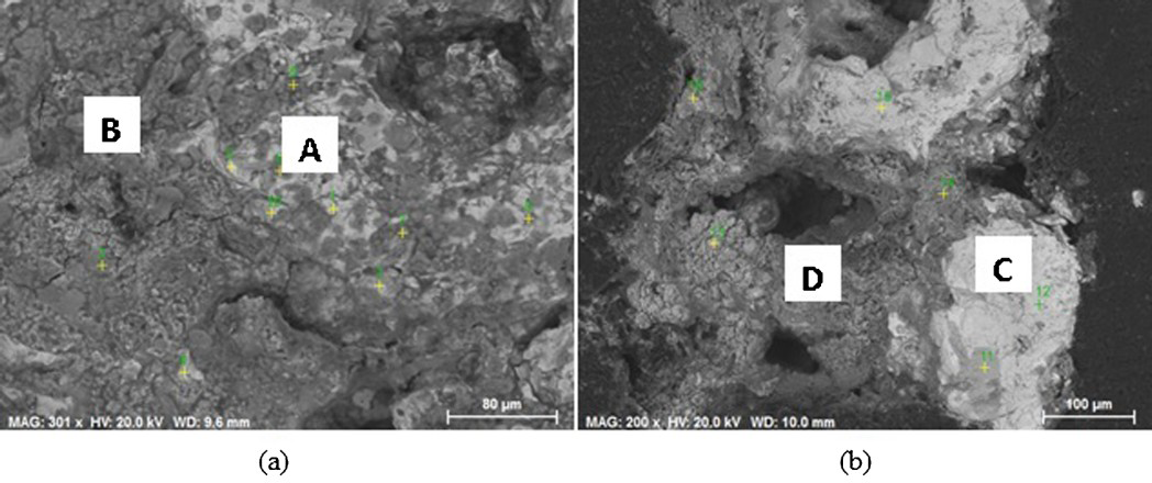
SEM images of cathode deposition after electrolysis of Nd–Fe–B magnet using AlCl3 as flux
Electrolysis was carried out at V = 3·4 V and T = 1073 K during 6 h. A is the metalic phase (Nd), B is chloride phase (NaCl), C is metallic phase (AlNd3) and D is oxychloride phase
The compositions of the various phases obtained from EDS analysis corresponding to Fig. 5a and b are presented in Table 2.
Composition of the metallic and chloride phases corresponding to Fig. 5a (mass pct)
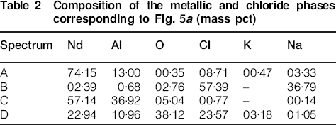
The data from EDS point analysis clearly show the presence of neodymium in the deposited product which is dominant in comparison to aluminium. There is no evidence of iron getting deposited on the cathode.
The XRD pattern of the cathode deposit is presented in Fig. 6.
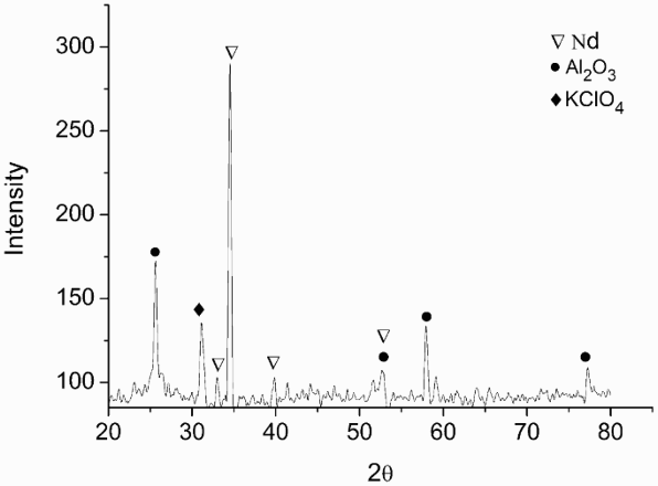
XRD pattern of neodymium deposit on graphite electrode in LiCl–KCl–NaCl molten salt at 1073 K
It is seen that the deposit consists of Nd metal as the dominant phase as well as Al2O3. The latter could have been the product of the oxidation of deposited aluminium metal and/or possibly the oxidised aluminium chloride electrolyte entrapped in the cathode. Nd peaks correspond to the hexagonal close packed structure of the metal. Except neodymium, peaks corresponding to Al2O3 and oxychloride phases are identified in the sample. KClO4 is likely to be entrapped as salt melt. Phases related to Fe and B were not identified in the deposit on the cathode.
Boron analyses in the salt bath as well as the cathode
As mentioned earlier, boron was not observed in the EDS analysis because of being a light element. Wavelength dispersive spectroscopy was used to detect boron in samples. As boron K and chlorine L peaks overlap in the energy dispersive spectrum, the higher energy resolution of WDS was needed to examine if boron was present in the samples. The boron content could not be quantified using standard methods as the samples did not have flat surfaces. An intensity scan over the boron peak position located at 0·1834 keV at scan speed 2 was therefore used as an alternative approach of detection. The energy of the boron K-line X-ray corresponds to a wavelength of 67·6 Å. The intensity scan over the peak position of boron is seen in Fig. 7. The existence of boron in the bulk salt bath sample was confirmed by WDS intensity scan over the boron peak position. In the bulk salt bath sample, the boron peak is obvious and above the detection limit. On the other hand, in the scan of the cathode sample, a peak is indicated but the intensity is not over the detection limit usually defined as three times the background intensity.
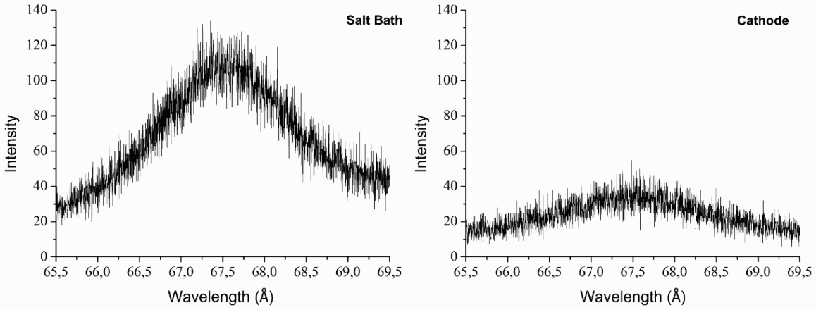
Intensity scan over the boron peak position in the salt bath sample and cathode sample
Discussion
In the following section, the electrodeposition process is examined.
The molten salt electrolyte
The electrolyte consists of LiCl–KCl–NaCl ternary eutectic. Aluminium chloride is added as the fluxing agent. Studies by Charlot and Tremillon (1963) and Lichum and Osteryoung (1981) have shown that aluminium chloride solute reacts with alkali chloride solvent and produces AlCl4− ionic species. Thus the salt bath can be considered as a pseudo-binary solution. Raman spectrometry carried out by Barbanel et al. (1990) has confirmed that, in molten alkali chlorides with low concentration of Nd3+, Nd (III) exists as NdCl63− complex with octahedral symmetry.
Electrode reactions
XRD results prove the presence of pure Nd on the sample while EDS results show that even Nd–Al alloy may be present in the deposited material. As mentioned earlier, only traces of boron could be found in the cathodic deposit. The cathodic and anodic electrochemical reactions of dissolved NdCl3 are


Study of chemical stability of Nd(III) in different molten salts is necessary in order to assess the electrochemical deposition of neodymium. Earlier studies on the reaction mechanism of Nd(III) ions in different molten salt systems show contradictory results.
Wu et al. (1994)
report that reduction of NdCl3 to Nd metal on a gold working electrode in a pure chloride melt is a one-step mechanism.
Hamel et al. (2004)
, in their experiments with LiF–CaCl2 melts,
Stefanidaki et al. (2001)
, with LiF melts at 1173 K (900°C), and
Nourry et al. (2009)
, with LiF–CaF2 at 1113 K (840°C), have confirmed the above mechanism in the Nd(III) reduction process. The reduction of Nd+3 on Al electrode also happens in one single step (
Serp et al., 2005
). However,
De Córdoba et al. (2008)
and
Masset et al. (2005)
have proposed that the reduction of NdCl3 takes place in two steps

The reduction process of most of the rare earth elements (La, Ce, Pr, Y) on a tungsten working electrode in molten chlorides showed a single group of signals; however in the case of Nd, two steps were identified by Castrillejo et al. (2003) .
Further studies on the fundamental aspects of the chloride melts containing Nd are required to get a clarification of the mechanism.
Over potentials
From Fig. 1 which shows the theoretical decomposition voltage of the metal chlorides, it can be seen that the decomposition voltage of AlCl3 is closest to NdCl3, compared to other chlorides present in the system. Therefore the co-deposition of Al would be expected.
According to equation (8), higher cathodic potential will lead to higher neodymium content, as the equilibrium potential is a function of the neodymium activity in the Al–Nd intermetallic phases (
Gibilaro et al., 2008
)
Co-reduction of Al(III) ions with neodymium ions would cause the neodymium ions potential move to more positive values. This phenomenon, termed as ‘depolarisation effect,’ would increase the extraction efficiency of lanthanides ( Nourry et al., 2009 ).
This depolarisation effect is expected in the case of binary systems which form intermetallic compounds. In the Al–Nd binary system, phase diagram exhibits six intermetallic compounds. The depolarisation phenomenon would be similar when using reactive cathodic material, which is another alternative to decrease the activity of the electrodeposited metal ( Gibilaro et al., 2009a ) since it is based on the same principle of the simultaneous reduction of two metals on the inert electrode ( Taxil et al., 2003 ). It has been shown that both copper and nickel react with rare earth materials at a high reaction rate and hence are considered as suitable reactive cathodic materials at temperatures about 1073–1173 K ( Nourry et al., 2009 ). Experiments with different cathodic materials are currently being carried out in the present laboratory.
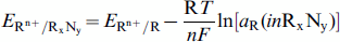
The present work is the basis for a new process line for the electrolytic recovery of neodymium in pure state together with as an alloy of aluminium from magnetic scrap. A possible flow sheet of the same is presented in Fig. 8.
Schematic diagram of the salt extraction process
The present approach to Nd recovery from magnetic scrap enables a separation of Nd from Fe. Because of the possibility of the separation of the rare earth metals in a single process step, the process is attractive from the point of view of implementation. Further, no elaborate sorting of the scrap would be needed as the selective electrodeposition helps in isolating Nd. The process also has the advantage of being environment-friendly as compared to the currently used hydrometallurgical approach since the salt bath can be reutilised without contaminating the environment.
Summary
Feasibility of the neodymium extraction from Nd–Fe–B magnet using molten salt electrodeposition method was investigated in this work. An experimental set-up was designed for the refining of neodymium from neodymium magnet (Nd2Fe14B). In this method, AlCl3 was used as the chlorinating agent, graphite rods as electrodes and eutectic composition of NaCl–KCl–LiCl as salt bath. NdCl3 was produced as the result of chemical reaction of neodymium magnet with AlCl3. Neodymium refining was performed successfully with Nd metal deposition on the cathode. The deposition of aluminium as oxide phase was also detected using EDS and XRD analysis. Further investigation is needed in the future in order to minimise the aluminium deposition on cathode.
Footnotes
Acknowledgement
The authors are thankful to Mr Babak Khalaghi for the valuable discussions during the present experiments. This work was carried out as an ‘off-shoot’ project of Eco-steel production, supported by Swedish Foundation for Strategic Environmental Research (MISTRA) through Swedish Steel Producers Association (Jernkontoret).