
Abstract
The crystallisation behaviour of perovskite in liquid synthesised titanium-bearing blast furnace (BF) slag (TiO2–SiO2–Al2O3–MgO–CaO) was observed in situ with a confocal scanning laser microscope (CSLM). Perovskite crystals were dendritic columnar crystals that nucleated on the crucible bottom (and wall) and grew to the centre and surface of liquid slag. The CSLM result that perovskite grew along straight lines through the successive appearances of quasi-particles on slag surface reflected the growth process of dendrites beneath the surface. The formation of perovskite required the diffusion of TiO2 and CaO to the solid interface at the dendrite tips and the rejection of SiO2, Al2O3 and MgO from the interface.
Introduction
In recent years, the comprehensive utilisation of the high titanium-bearing blast furnace (BF) slag produced from iron and steel industries has aroused wide concern for the environmental protection and the utilisation of titanium resources. This is a particularly important issue in China, where large deposits of vanadium titanium magnetite ores are found in the Panzhihua-Xichang area. More than 50% of titanium in the raw ores finally enters the slag through the BF process, forming the typical titanium-bearing BF slag, which contains 22–25wt-% TiO2 (Xiong et al., 2008). China has accumulated more than 70m t of titanium-bearing BF slag and its amount is still increasing at about 3·5m t year−1. To extract the valuable titanium and reduce the environmental pollution caused by the stacking of slag, many processing methods have been studied such as acid leaching (Liu and Sui, 2002), alkaline leaching (Zhou et al., 1999), Ti–Si alloy preparation (Li et al., 1996), TiC preparation (Li et al., 2005), concentrating titanium in rich-titanium phases, etc. However, none of them are used in industry because of the high cost, secondary pollution, and narrow market.
Gathering titanium into perovskite was considered to be a promising technology once. However, the intertwining and symbiosis of the fine and uneven perovskite grains with other phases, which is adverse to following mineral separation, hinder the application of this technology. Recently, Guo Zhancheng proposed a new technology to separate perovskite phase from titanium-bearing slag by use of the centrifuge at high temperature (above 1573 K) and got a high TiO2 recovery ratio (Gao et al., 2014). Ultimately, the crystallisation of perovskite is keys to the perovskite extractive process. In current work, the crystallisation behaviour of perovskite in molten synthesised titanium-bearing BF slag (TiO2–SiO2–Al2O3–MgO–CaO) was observed in situ using the confocal scanning laser microscope (CSLM).
Confocal scanning laser microscope has been successfully used to study the high-temperature behaviour of slag system. Orrling et al. (2000) studied the role of alumina particle in SiO2–CaO–Al2O3–MgO slag by CSLM. Semykina et al. (2011) observed the crystal growth of liquid FeO–CaO–SiO2 slag during oxidation by using CSLM. Sridhar and Cramb (2000) described the kinetics of Al2O3 dissolution in the CaO–MgO–SiO2–Al2O3 slag with CSLM.
Experimental method
Sample preparation
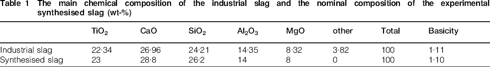
The synthesised slag was prepared by using the analytical reagent CaO (98%), MgO (98%), SiO2 (99%), TiO2 (99%) and Al2O3 (98%) powder with the nominal composition as shown in Table 1.
The main chemical composition of the industrial slag and the nominal composition of the experimental synthesised slag (wt-%)
Mixed oxides powder (100 g) was placed in a molybdenum crucible, and then the crucible was placed in the furnace using MoSi2 heating elements at room temperature. Then the powder was heated to 1773 K at the heating rate of 5 K min−1 and was maintained at that temperature for 1 h under an argon atmosphere (Ar>99·99%) to melt the mixed oxides and form the homogenised synthesised slag. Finally, the molten slag was cooled in water. The cooled slag was cut and polished into proper size for the following CSLM observation.
CSLM experiment
Before the CSLM experiment, the slag sample was cleaned by ultrasonic cleaner using alcohol as a solvent. After that, the cleaned slag sample was placed into a platinum crucible (inner diameter of 8 mm and height of 5 mm) and the crucible was in turn placed on the platinum holder fixed in the infrared furnace, at room temperature. Before heating, the infrared furnace was evacuated and back-filled with argon (Ar>99·999%) three times. Then the slag sample was heated to 1773 K at 300 K min−1 and held for 5 min to totally melt the slag. Afterwards, the slag was cooled at a cooling rate of 10 K min−1 to observe the crystallisation process. The temperature was measured by a B-type thermocouple welded on the bottom of the platinum holder. The accuracy of the infrared furnace temperature was confirmed by melting experiments of pure copper (melting point: 1356 K) and pure nickel (melting point: 1726 K). The temperature–time data and the video of the crystallisation process of the slag during cooling were stored on the computer connected with the CSLM.
The polished surface of slag sample was analysed using scanning electron microscopy (TESCAN VEGA) after the CSLM experiment. Energy dispersive spectrometer (OXFORD INCA Energy 350) equipped with SEM was employed to analyse the chemical composition. X-ray diffraction (XRD: D/max 2500°C) analysis was also carried out.
Results and Discussion
Thermodynamic calculation
The equilibrium phases of the synthesised titanium-bearing slag at different temperatures were calculated by using FactSage 6·3, as shown in Fig. 1. It can be seen that the melting temperature of the slag is predicted to be 1710 K. Perovskite is the primary phase crystallising from the molten slag during cooling. Titania spinel and clinopyroxene are predicted to crystallise at 1598 K and 1498 K, respectively. At the end of solidification, a small amount of TiO2 is predicted to crystallise.
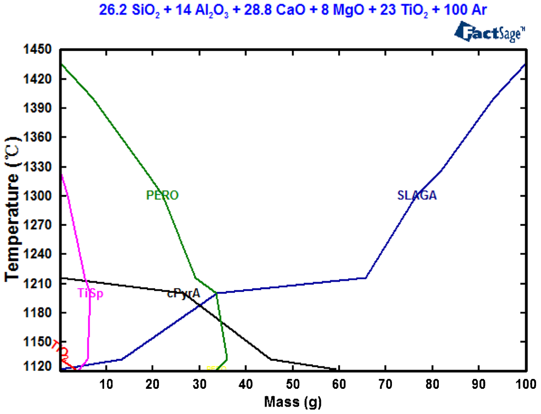
Theoretical equilibrium phases of the synthesised titanium-bearing slag at different temperatures (SLAGA, liquid slag; PERO, perovskite; cPyrA, clinopyroxene; TiSp, titania spinel; TiO2)
Crystallisation process
The crystallisation process on the slag surface can be observed in situ by CSLM. Figure 2 shows the crystallisation process of the molten slag from 1733 to 1504 K cooled at 10 K min−1. The slag was totally liquid above 1733 K and the liquid phase presented bright white. Several crystal quasi-particles appear from the liquid slag at 1733 K. With the temperature decreasing, the new crystals appear randomly, and the old ones grow along straight lines through the successive appearances of quasi-particles. With the growth and coarsening of crystals, the amount of liquid phase decreases gradually. The molten slag is almost completely solidified at 1504 K, which is similar to the results of the calculation by FactSage 6·3.
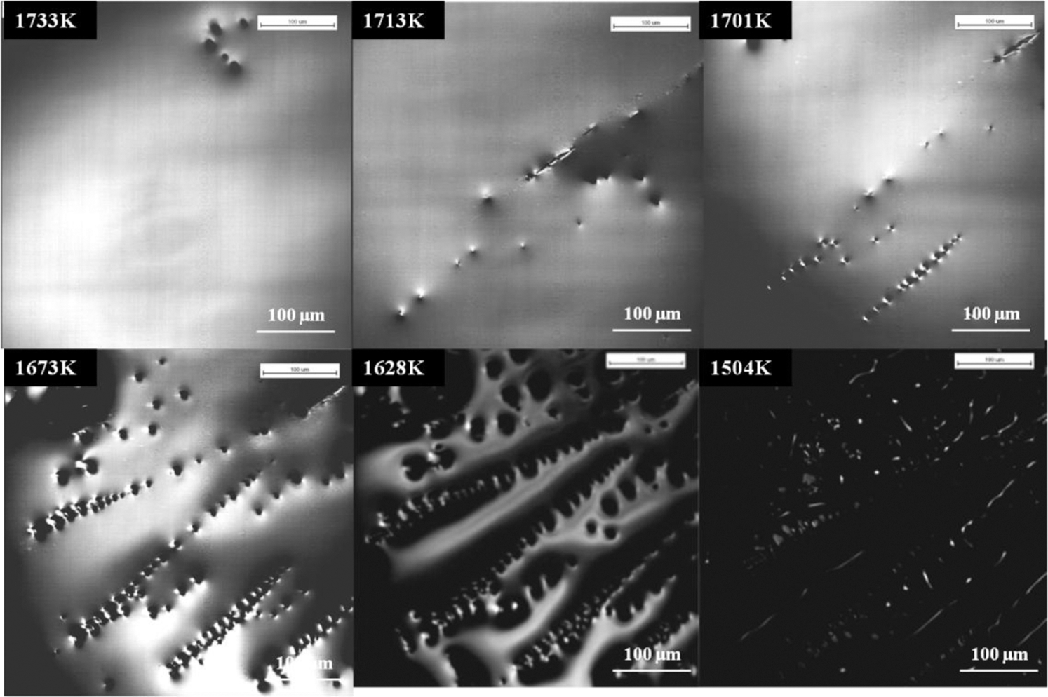
The crystallisation process of the synthesised slag with the temperature decreasing at a cooling rate of 10 K min−1
The fact that the quasi-particles appear along straight lines suggests that they are not individual particles, but that they are connected beneath the surface and are the secondary arms of dendrites that have nucleated and grown beneath the surface.
Crystalline phase and morphology
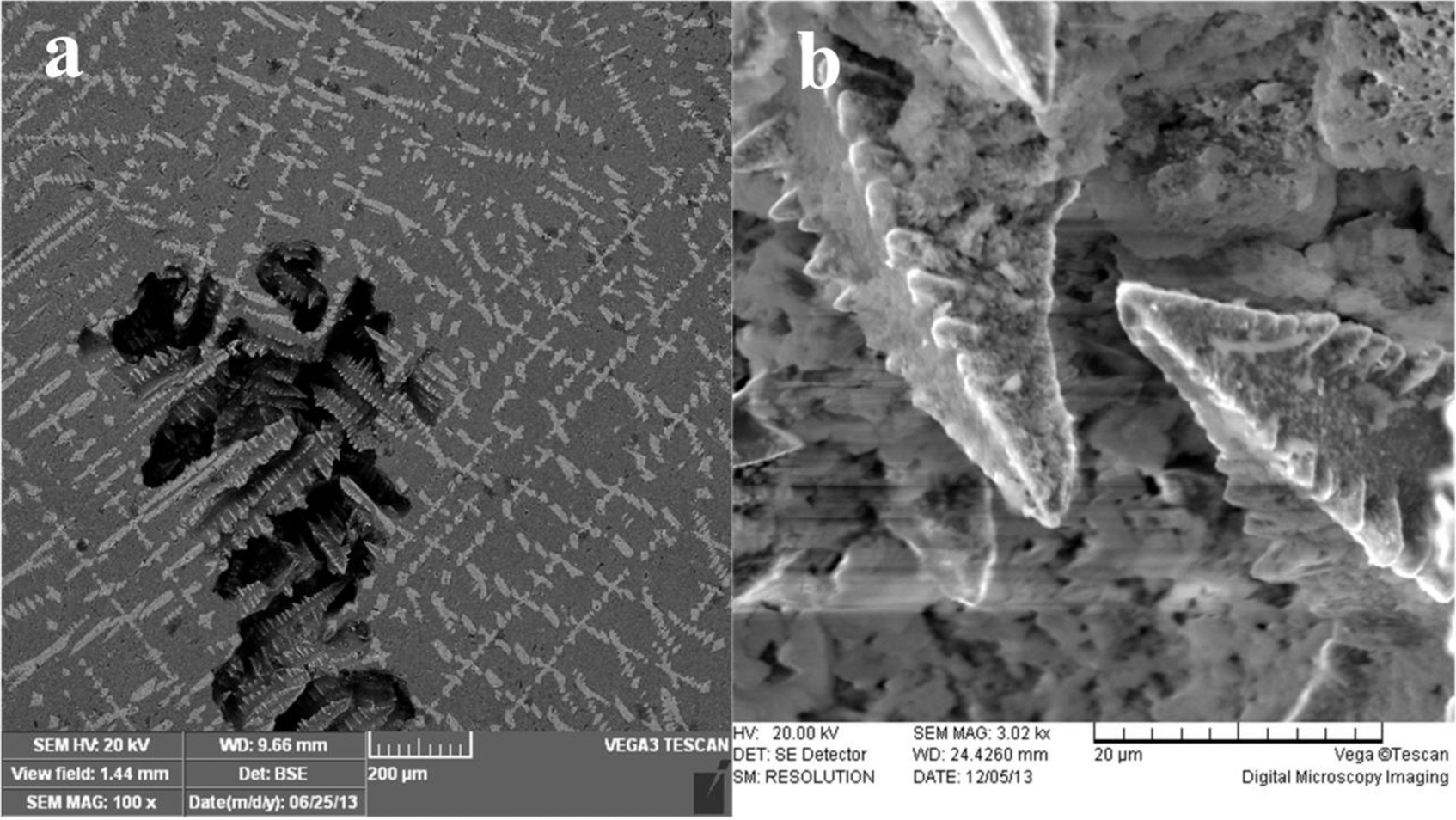
Figure 3 and Table 2 display the morphology and the chemical composition of the cross-section of a polished sample cooled at 10 K min−1. It can be seen that the light-colour crystals present dendrites and the cross-section of the dendrite arms is a quadrilateral shape. And the quadrilateral grains on a same straight line are also not individual but grow from the same dendrite arm. Some crystals are superimposed, forming an irregular morphology, which indicates the intersection of dendrites.
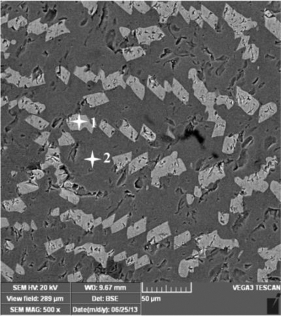
The SEM images of the polished slag sample after CSLM experiment
The EDS spot scanning results of 1 and 2 spot in Fig. 3 (atomic per cent)
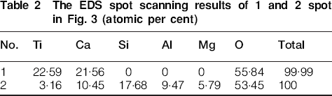
The XRD result in Fig. 4 shows that CaTiO3 and CaMgSi2O6 form during cooling. It can be seen from Table 2 that Ti, Ca and O elements are the main elements in the light-colour crystals and their atomic per cent is close to 1∶1∶3, suggesting that the crystals are perovskite. The grey zone that has no specific crystal morphology on the SEM images contains Si, Ca, Al, Mg, O and a small fraction of Ti elements. As a result, the dendrites observed under CSLM are perovskite, while CaMgSi2O6 was not observed probably because it did not form yet within observable experimental temperature or it has no clear specific crystal morphology. Except for CaTiO3 and CaMgSi2O6, other phases predicted in the thermodynamic calculation were also not observed under CSLM probably because their amount is too small to be detected or they do not have enough time to crystallise at the fast cooling rate and form an amorphous glass phase, which is indicated in the XRD by the amorphous peak.
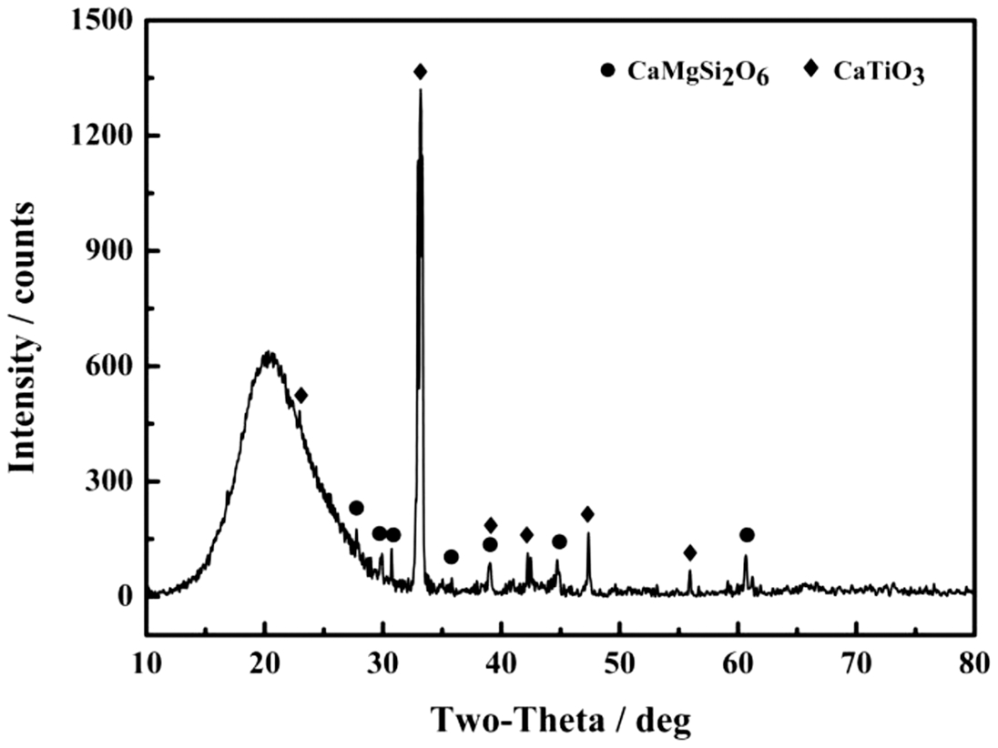
The XRD pattern of the slag sample cooled at 10 K min−1
The cross-section morphology of the perovskite shows a good agreement with that in published papers. In most researches, the size of a single quadrilateral grain on the two-dimensional cross-section of slag is used to represent the crystal grain size and coarsening degree of perovskite (Zhang et al., 2007). However, as mentioned before, the quadrilateral grains are not individual, and a single quadrilateral grain is not able to comprehensively represent the size or structure of perovskite dendrite.
The spatial structure and growth of perovskite
Because of shrinkage during cooling some voids remained in the solidified slag, as shown in Fig. 5a. The voids show the intact perovskite dendrite structure, which is dendritic columnar crystal. When solidified in casting, crystals precipitated preferentially at the interface between metal and mould because the mould has lower temperature. The equiaxed grains forming on the mould surface will continue to grow in preferred crystallographic directions and form dendritic columnar crystals (Kurz and Fisher, 2010). In the CSLM apparatus, heat radiation reaches to the slag surface through the reflection of radiation by the gold clad layer in furnace chamber. So when cooling the slag, the heat will flow from the slag surface to the crucible bottom by conduction, then flow away by radiation from the crucible bottom, which makes the bottom lower temperature. As a result, the dendritic columnar crystals grow from the crucible bottom to the centre and surface of slag as shown in Fig. 5b. The crucible wall probably exhibits the similar situation.
SEM images of the polished slag sample with voids and dendrite structure: a the surface of the polished slag sample with voids; b the intact dendritic columnar crystals of perovskite
It is clear that the quasi-particles on slag surface observed through CSLM in Fig. 2 must be the secondary dendrite tips, which have arisen from the nucleation of dendrites under the liquid surface. With the dendrite arms producing successively, secondary dendrite tips appear on the surface along straight lines. The cross-section of the dendritic columnar crystal (Fig. 5b) should be square because ideal perovskite crystallographic structure is cubic. Quadrilateral shape may be caused by various cutting angles.
The growth of the dendrites presumably follows classical theory illuminated by Kurz and Fisher (2010). The actual ionic species in the slag will presumably include Ca2+, Mg2+, Ti3+, Ti4+, O2−, TiO44−, and SiO44−. To simplify the situation, the initial slag is considered to be made up of oxides. In perovskite, the molar ratio of TiO2 to CaO is 1 and its formation requires the diffusion of TiO2 and CaO to the solid interface at the dendrite tips and the rejection of SiO2, Al2O3 and MgO from the interface. The TiO2 and CaO in solution will diffuse together against the other oxides and ‘react’ at the interface to form solid perovskite. But not all the CaO and TiO2 will form perovskite, some will be also rejected because there is a mass balance at the interface. Because other oxides do not form the solid phase, they can be considered as an ‘inert phase’. Solidification of perovskite makes the slag at the moving dendrite tip interface have lower amounts of TiO2 and CaO, and a lower liquidus temperature than the bulk slag. With a low actual temperature gradient in the liquid this leads to constitutional supercooling and to the observed dendritic growth, in agreement with classical theory. The shape of dendrite tip and the mass and heat transportation will influence each other, which will be investigated in the future.
Conclusion
The crystallisation behaviour of perovskite in liquid synthesised titanium-bearing BF slag can be observed in situ with a CSLM. On slag surface, perovskite quasi-particles appear along straight lines through the successive appearances of the secondary dendrite tips of dendrite arms that have nucleated and grown beneath the surface.
Perovskite crystals are dendritic columnar crystals that nucleate from the crucible bottom (and wall) and grow to the centre and surface of liquid slag. The quadrilateral cross-section of the dendrite arms reflects the cubic crystallographic structure of the perovskite.
The formation of perovskite requires the diffusion of TiO2 and CaO to the solid interface at the dendrite tips and the rejection of SiO2, Al2O3 and MgO from the interface.
Footnotes
Acknowledgement
The authors are thankful to the National Natural Science Foundation of China for the financial support through the project (No. 51090383). The financial support (Project No. CDJZR12130049) for the research from Fundamental Research Funds for the Central Universities is gratefully acknowledged.