
Abstract
The experimental study was focused into effects of a ceramic refractory lining, covering a metallic cooling element, as well as to properties and microstructures of the freeze lining formed in such cases in copper smelting and converting slags. The modified heat transfer pattern, due to the ceramic refractory lining and its air gap(s), increases effectively the average freeze lining temperature, heating its cold face from 30 to 50°C of the direct contact close to 800–900°C, even with refractory thicknesses of a few millimetres. This general feature has direct consequences to the microstructure and thickness of the freeze lining and probably also to its growth rate. The observations about effects of high copper iron silicate slag on the chemical corrosion of direct bonded magnesia–chromia refractories suggest that copper oxides are not the most aggressive components of direct to blister smelting slags. Impregnation of the fluid direct to blister slag into the open porosity of the brick, even on the cooled furnace wall, extends quickly in the initial contact several hundred micrometres into the refractory.
Introduction
Dedicated ceramic lining constructions protect pyrometallurgical furnaces and their engineering designs from the hot smelting and refining products as well as its chemical environment. The components of refractory lining materials depend on the application, processing vessel and its operation mode. In copper making, the ceramic refractory linings rely on the good refractoriness of magnesia. In such cases, the chemical resistance against silicate slags is achieved by chromia and its reaction products with the brick matrix, typically MgO rich chromites (Malfliet et al., 2014). Owing to significant intensification of the copper smelting processes over the last 2–3 decades, chemical dissolution of the refractory material into the large slag volume treated by the current copper and nickel smelters is prone to shorten seriously the campaign life. This is against the needs of the industry where longer campaigns are regarded as favourable, with a high online availability of the smelter. As a strategy for extending the campaign lives and ensuring the smelting vessel integrity as long as possible, various furnace wall cooling devices and technologies have been developed. They generate an autogenous layer or lining on the ceramic refractory wall construction from the process slag, by an external forced cooling effect. In the modern highly intensive processing technologies, such as the flash smelting furnace (Kojo et al., 2000) or the TSL Furnace (Hughes et al., 2008), the entire furnace vessel can be lined by smelting products with forced, continuous effect by copper cooling elements (Verscheure et al., 2006b; Fagerlund et al., 2010; Wang et al., 2013).
The impact of the cooling elements to the heat balance is often of minor importance, but the extension of the campaign life may be one order of magnitude (Kojo et al., 2000). This, however, requires careful maintenance of the processing environment and continuous monitoring of the conditions within the refractory wall and the entire smelting vessel (Björklund et al., 2013).
The mechanisms of freeze lining formation have been discussed in the literature on various levels, ranging from a macroscopic approach (Bruggeman and Danka, 1990; Campforts et al., 2007) to a detailed microscopic analysis of the layer and its properties when exposed to molten slag in a temperature gradient (Verscheure et al., 2006a; Campforts et al., 2009; Fallah-Mehrjardi et al., 2013a, 2013b). In most cases, focus of the experimental studies on freeze lining formation kinetics and mechanisms has been in direct growth on a water cooled metal surface (Campforts et al., 2007, 2009; Fallah-Mehrjardi et al., 2013a, 2013c). This is valid case, however, in a part of the industrial freeze linings only, as many furnace designs, at least initially, have a brick layer between the molten slag and the cooler (Taniguchi et al., 2006), or the cooling elements have ceramic refractory bricks as an integral part of their design (Wu et al., 2008; Fagerlund et al., 2010). It can be assumed that, in such cases, the maximum heat transfer rate and the heat flux are much lower than in direct contact of the slag with the cooling element. It is also obvious that every air gap forms a potential resistance to the heat transfer within a refractory wall of composite structure.
The freeze linings formed directly on the metal surface of a cooling element show typically three structurally different zones, formed during the fast initial growth of the layer (Taskinen et al., 2011; Fallah-Mehrjardi et al., 2013b). The cold end against the metal surface is glassy or microcrystalline within the first few millimetres. Towards the hot end, this glassy zone turns to more or less crystalline non-porous body of the lining, the ‘sealing layer’ (Fallah-Mehrjardi et al., 2013a, 2013b, 2013c), where the crystallising phases are embedded in a glassy matrix. In copper matte smelting slags, the crystalline phases are mostly magnetite but depending on the gangue mineralogy and age, also fayalite (‘olivine’) and other silicates may be present (Taskinen et al., 2011; Fallah-Mehrjardi et al., 2012). In the silica fluxed copper converting or direct to blister (DtoB) slags, the prevailing high oxygen pressure increases the chemically dissolved copper concentration and causes growth of crystalline delafossite (CuFeO2) at lower temperatures of the freeze lining, thus binding also a fraction of ferric iron oxide from the slag (Taskinen et al., 2012). Towards the hot end, the porosity increases, and thus, mechanical strength of the freeze lining decreases. It obviously vanishes clearly below the liquidus temperature of the slag (Fallah-Mehrjardi et al., 2013a, 2013b). The freeze lining against the molten slag and its hot end temperature never reaches the liquidus temperature of the slag because, at that temperature, no solid network of crystals exists but only scattered crystals of the primary phase in the molten slag. The experimental freeze linings as well as samples from industrial furnaces have also a thin slag layer on their surfaces, which may be distinguished from the actual freeze lining by its chemistry and microstructure.
The first water cooled furnace wall constructions for extending the campaign lives and improving the online availability were suggested for the flash smelting furnace already in 1950s (Kojo et al., 2000). They are today used in all copper and nickel smelters producing either copper and nickel matte or blister copper (Fagerlund, 2013). Similar local cooling technologies and freeze linings are used in various ferrous metals and ferroalloys production vessels (Manning and Fruehan, 2001) as well as in special applications in the energy and pulp industries (Li et al., 2009; Chen and Ghoniem, 2013).
This study was focused on the effects of a refractory lining layer covering the water cooled metal surface, as well as to properties and the microstructures of the freeze lining in copper rich copper smelting and converting slags. In such processes, the smelter products are typically close to or in equilibrium with metallic copper. The attention was paid to two main features, namely, the microstructure of the formed freeze lining and the lining–refractory interactions by the slag or freeze lining. The intention was to find out qualitatively how the prevailing heat transfer pattern is changed when the cooling element is covered with a ceramic, by nature insulating refractory lining, and with an air gap between the water cooled metal and the ceramic refractory layer in true smelting conditions, at elevated temperatures.
Experimental
The water cooled probe technique introduced in Verscheure et al. (2006a) and Taskinen et al. (2011) was used in this study. The method is based on submerging a water cooled stainless steel probe, equipped with a number of thermal sensors, into the liquid slag. Because of the thermal imbalance between the slag bath and the water cooled probe, a freeze lining is solidified on the surface of the probe from the surrounding molten slag bath. The experimental set-up was further improved for more accurate measurements of the heat transferred into the cooling water under the slag layer. The water temperature inside the probe was measured with six A Class PT100 platinum resistance thermal sensors, including one for inlet and outlet as well as four locating in the tip of the probe. The temperature of the slag bath was measured with a calibrated S-type thermocouple (Johnson-Matthey, UK) outside the crucible, in an alumina sheath with a diameter of 4 mm.
The construction of the probe with the refractory sleeve is illustrated schematically in Fig. 1. The refractory sleeve was made of a commercial magnesia–chromia (MagChrom) brick (Radex OX-6; RHI AG, Austria), which is a ceramic (direct) bonded material made of sintered magnesia, oxicrom sinter and chrome ore. Its major components are MgO (59.5 wt-%), Cr2O3 (19 wt-%), Fe2O3 (13.5 wt-%) and Al2O3 (6 wt-%). Apparent porosity of the brick material is 17% (RHI, 2014). It is a refractory material grade used typically in the flash smelting furnace bottom and sidewall refractory linings. The used sleeves were drilled by diamond tools from the as received brick.
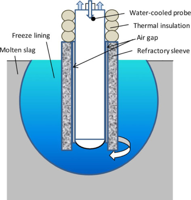
Schematic picture of tip of water cooled cold finger with ceramic sleeve between molten slag and cooling element; o.d. of steel probe is 14 mm
The slag was held in a dense magnesia crucible (Ozark Technical Ceramics Inc., USA). Its dimensions were 95 × 150 mm (o.d. × H), and a rotating speed of 10 rev min− 1 was used during heat-up and immersion of the probe. The set-up and the experimental procedures used have been described in our previous papers (Taskinen et al., 2011; Jansson et al., 2014) in more detail. In this study, the probe and the slag bath were allowed to stabilise thermally before immersion into the molten slag, by an extra heat-up period of 10 min just above the slag surface.
The slag used in the experiments was industrial high copper slag from an operating DtoB smelter (Taskinen and Kojo, 2009). Its copper concentration was adjusted by adding Cu2O oxidised from A grade cathode copper (Boliden Harjavalta Oy, Finland) with a purity of >99.99%Cu. The oxidation was carried out in air at 1030°C, above the decomposition temperature of CuO in air, in a muffle furnace. After oxidation, the produced Cu2O was crushed to a 1–3 mm particle size.
After 30 min submersion time the probe, ceramic sleeve on it and its freeze lining were lifted from the molten slag bath with the protective nitrogen flow on. The electric motor of the probe elevated them in 20 s from the hot zone to the roof of the furnace frame. The formed freeze lining was then quenched in tap water until it stopped boiling. After that, residual slag in the crucible was sampled with dip rod using a 4 mm iron bar (‘end slag’ in Table 1), as described earlier (Taskinen et al., 2011). The fast quenching maintained as much as possible the original microstructure of the 150–300 g sample and protected together with the thin slag layer the actual freeze lining from oxidation during cooling.
Analysed bulk chemistries of DtoB slags in freeze lining growth experiments/wt-%
refractory sleeve on the water cooled probe.
From each experiment, a set of slag samples was prepared. Two slag samples were taken with dip rod for determining the compositions of the slag bath, in the beginning and in the end of an experiment (see Table 1). A third sample for chemical analysis was cut from the solidified, cold slag remaining in the MgO crucible after each experiment. The slag chemistries were determined post-sample homogenisation using inductively coupled plasma spectrometry, Satmagan (Fe3O4) and wet chemical analysis (SiO2). The freeze lining obtained was sliced by a diamond wheel, cast in an epoxy resin and a polished cross-section was prepared for scanning electron microscope–energy dispersive spectrometer (SEM-EDS) observations using standard wet methods.
The freeze lining cross-sections obtained were examined with a LEO 1450 scanning electron microscope equipped with a tungsten cathode (Carl Zeiss AG, Germany). For imaging, a 15 kV acceleration voltage at 15 mm working distance and the backscattered electron (BSE) mode were used. The phase compositions of were studied with an INCA X-Max EDS analyser (Oxford Instruments, UK) using mineral standards manufactured by SPI Supplies Inc. (West Chester, PA, USA). INCA Energy uses the XPP matrix correction scheme developed by Pouchou and Pichoir (1992) and supplied by Oxford Instruments. Selected freeze lining samples were examined with X-ray diffractometry (XRD; Bruker AXS D8 Focus, USA) to identify their crystalline phase assemblies.
The conditions of the freeze lining growth experiments were constant in each experiment. The slag temperature was 1350°C, and the magnesia crucible was rotated at a rate of 10 rev min− 1. Flowing dry nitrogen (Aga-Linde, Finland) with a purity of 99.99% was used as protective atmosphere, lead to the centre of the furnace at a rate of 3 L min− 1 (standard temperature and pressure). Cooling water flow to the cold finger varied slightly from one experiment to another. The flowrate was measured before each run, and it was 2.1 ± 0.1 L min− 1 in the experimental series. The temperature data measured by the thermal sensors within the probe and the furnace were stored in a PC-HD using a few second intervals.
In total, four freeze lining runs were performed in this study with copper concentration of the slag as variable. Two runs were performed with the refractory sleeve on the water cooled probe. The dimensions of the sleeves were L = 120 mm, i.d. = 16 mm and o.d. = 19 and 35 mm. The refractory lining thicknesses were 1.5 and 9.5 mm respectively. Thus, an average of 1 mm air gap was between the cold finger and the refractory sleeve. The immersion depth of the probe, determined separately each post-experiment, varied from 21 to 30 mm. The chemical analyses of the slags in each experiment were collected in Table 1.
Owing to the special gangue mineralogy of the DtoB smelter feed mixture, potassia concentration of the used slag was relatively high, and the high lime concentration is a consequence of fluxing the iron oxides with lime (Taskinen and Kojo, 2009). The sum of oxides based on the analysis was 95–98%, which indicates that a fraction of ferric oxide is not included in the Satmagan analysis as magnetite.
Results and Discussion
The freeze lining microstructures generated on the water cooled surface with and without the refractory lining can now be easily compared, as the conditions in the experimental set-up were carefully controlled and a similar slag was used in all runs. The average thicknesses of the solidified layers on the probe varied a lot. Those directly on metal solidified layers were 20 ± 2 mm thick, but on the thin 1.5 mm refractory sleeve, it was 15 ± 1 mm and on 9.5 mm sleeve only 3.5 ± 1 mm. The estimated super heat of the slag, evaluated by thermodynamic properties of the slag according to Mtox database (Gisby et al., 2002), was 220 ± 20°C in all cases.
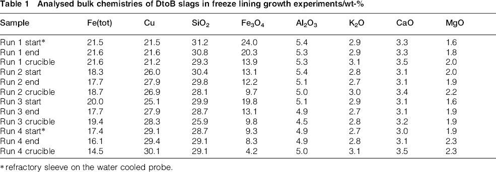
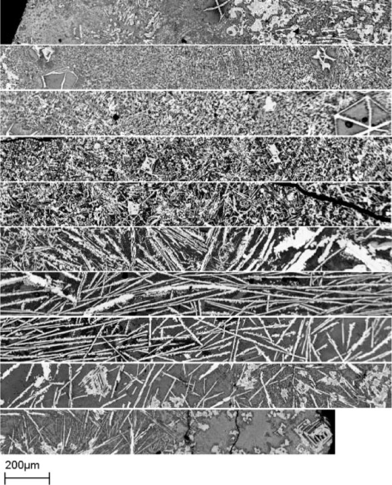
The microstructures of the freeze linings formed on the refractory sleeve did not have the familiar and characteristic glassy layer in the cold end, as reported on the previous studies (Taskinen et al., 2011; Taskinen et al., 2012; Fallah-Mehrjardi et al., 2013a). Figure 2 shows a panorama composed of several SEM BSE images from the cold end (upper left) to the hot end (lower right) of the formed freeze lining. The base slag with 21.5wt-%Cu was used. The thickness of the freeze lining on the refractory sleeve was always clearly smaller than that formed directly on the metallic cold finger.
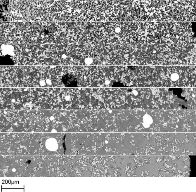
Image (BSE) panorama throughout freeze lining formed in DtoB slag of 21.5 wt-%Cu within 30 min immersion at 1350°C; each horizontal strip is 1.75 mm long, and total thickness of solidified sample was 14 mm (1.5 mm brick sleeve on cold finger)
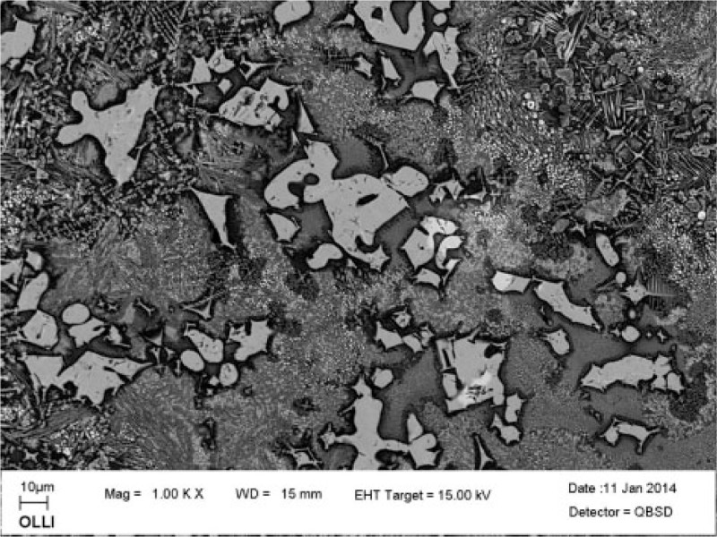
The microstructure of the freeze lining formed on the refractory sleeve is a sign of much lower cooling and solidification rate of the slag layer in the slag probe contact. The microstructure is much more uniform throughout the layer than in cases when the solidification takes place directly on the water cooled metal surface. This can be seen in Fig. 3 where the solidified slag next to the refractory is shown as an SEM-BSE image. The structure is composed of magnetite (a spinel type solid solution) crystals coated with delafossite. It was present also as independent needle-like crystals. The intergranular glassy phase contains randomly scattered, relatively large (15–20 μm) copper droplets.
Magnetite precipitates (light grey) coated with delafossite (white) in glassy intergranular matrix of freeze lining next to MagChrom sleeve on water cooled steel probe; 20.1 wt-%Cu in initial slag
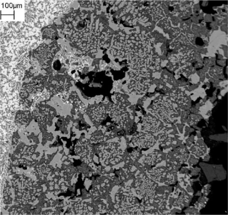
The freeze lining formed directly on the water cooled probe generated, as a result of the effective heat transfer and cooling, in this slag more than 5 mm thick microcrystalline zone next to the metal surface, as shown in Fig. 4. The microcrystalline zone and its structure were similar to those obtained earlier with the same DtoB slag and described in the earlier publication (Taskinen et al., 2013). It contained randomly distributed, relatively large magnetite crystals in a very fine crystalline matrix next to the probe surface in the cold end. No clear columnar structure could be identified in the crystalline magnetite, and particularly, the delafossite needles were randomly oriented without any preference to the direction of the heat flux. This is an indication of the slow and difficult nucleus formation step in the devitrification and crystallisation of the quickly undercooled silicate slag.
Cross-section of freeze lining formed directly on water cooled cold finger from DtoB slag, with initial copper concentration of 26 wt-%, in 30 min immersion at 1350°C; each horizontal strip corresponds to thickness of 2.5 mm in 25 mm thick freeze lining
The limited thermal stability of delafossite in the Cu–Fe–O system may be used as a tracer for the temperature profile within the freeze lining. The upper stability temperature of CuFeO2 is about 1170–1180°C (Hidayat et al., 2012). Above that temperature range, spinel replaces delafossite in the solidification path. It nucleates either heterogeneously on (primary) magnetite crystals or homogeneously as needles embedded in the intergranular glassy phase.
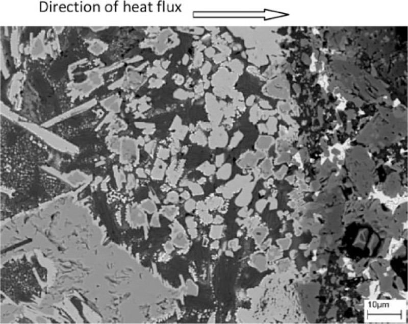
The high copper concentration of the studied DtoB slag modifies the morphology of the primary magnetite from the euhedral dendritic crystals, found typically in the matte smelting freeze linings (Taskinen et al., 2011). Here, the primary magnetite was precipitated as massive crystals, whereas secondary magnetite is present as small dendrites, as shown in Fig. 5. Note the dark diffusion zones depleted by iron around the forming magnetite crystals. The precipitate density is much lower in the glassy layer of the lining, compared to the lining formed on the refractory sleeve.
Primary and secondary magnetite (grey) and small cuprite (white) crystals in microcrystalline zone of freeze lining, on cold end towards water cooled metal surface: DtoB slag with initially 25.1 wt-% copper; no refractory sleeve
Cuprite (Cu2O) precipitates in the freeze lining at high temperatures, above the upper stability temperature of delafossite. The primary cuprite forms as dendrites and secondary as very small spherical crystals, as demonstrated in Fig. 5. It contained 1–2 wt-% iron. Based on the Cu–Fe–O phase diagram, cuprite is formed in eutectic reaction at the copper concentrations of the current slags. Cu2O is not part of the stable system at low copper concentrations. At magnetite saturation, the Cu–Fe–O systems needs copper concentrations of more than 50 wt-%Cu2O, and delafossite is stabilised in the system below ∼1180°C. This is visualised in Fig. 6 as a composite of the liquidus isotherm and 1170°C isothermal section of the system Cu2O–FeO–Fe2O3 in the Cu2O corner. The phase diagram was calculated by MTDATA software using the extensive slag database Mtox, version 8.0 (Gisby et al., 2002), as the source of thermodynamic data.
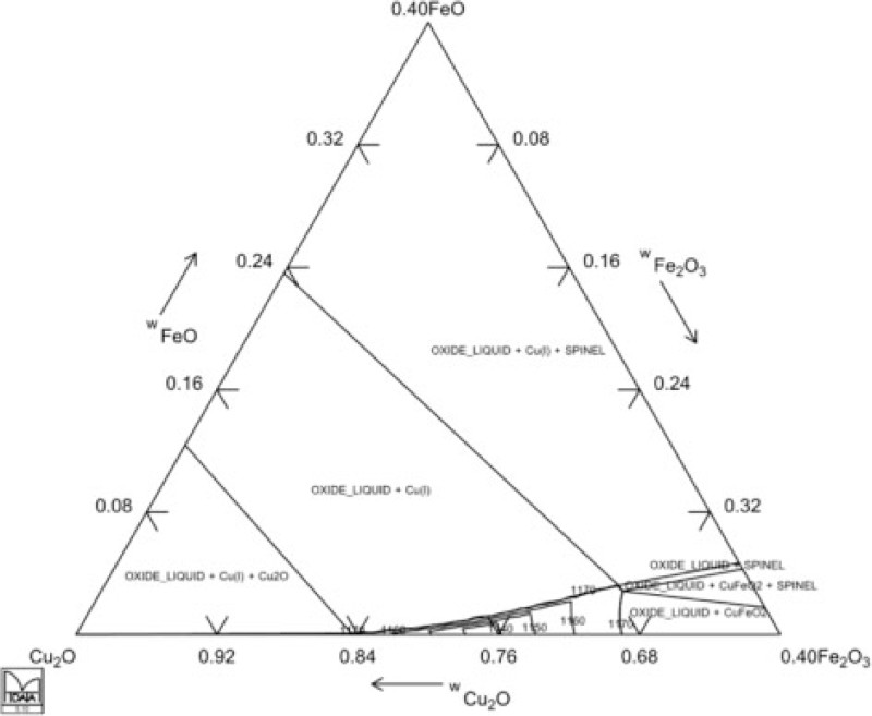
Liquidus isotherms and 1170°C isothermal section of ternary system Cu2O–FeO–Fe2O3; gradual displacement of delafossite by magnetite (‘spinel’) at 1160–1170°C is shown and primary solidification products of liquid copper–iron oxides close to Cu2O corner
The freeze linings were composed of magnetite, delafossite, occasionally cuprite and the intergranular, microcrystalline phase. Delafossite and magnetite identified by XRD were always on the cold face of the freeze lining, with or without the refractory sleeve. The fast cooled outer slag shell and its microstructure is of no importance in this study, as it is not part of the freeze lining at high temperatures and the microstructure is subject to local quenching.
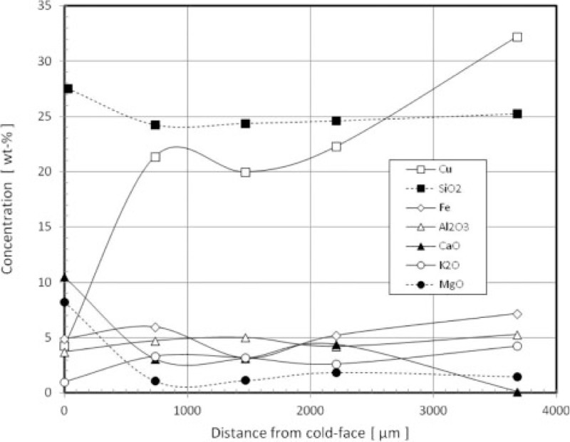
The elemental compositions of the phases were determined by EDS techniques as a function of the thickness, in order to characterise mineralogy of the formed freeze linings. Figure 7 shows the compositional profiles of selected elements in the intergranular glassy matrix as a function of thickness of the lining, formed on the 1.5 mm thick refractory sleeve in a 21.5% copper containing slag. The copper concentration profile indicates that ∼3 mm of the total layer thickness of 14 mm is actually remnants of the slag attached to the freeze lining, formed during the 30 min immersion. The indicated trends are typical even if differences exist next to the precipitates. The hot face slag layer is shown schematically in Fig. 7 as the grey arrow.
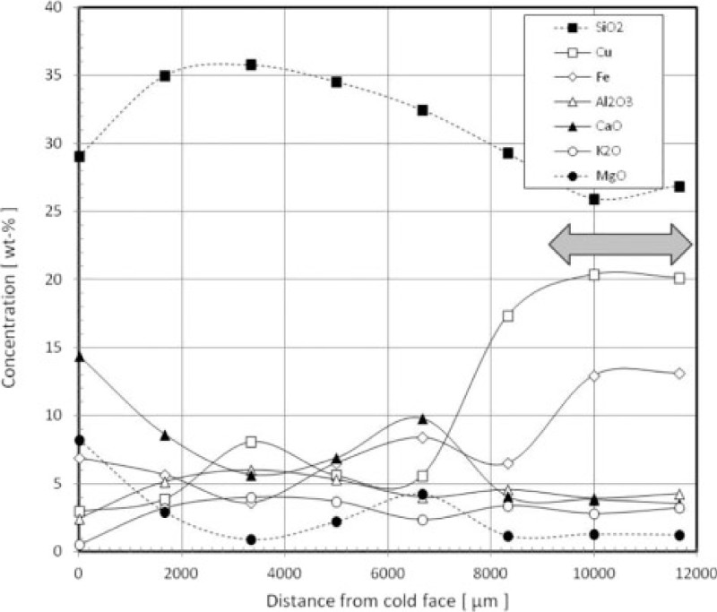
Composition of intergranular, glassy phase as function of layer thickness from cold end; 1.5 mm refractory sleeve, copper concentration of slag was 20.1 wt-% and grey arrow indicates depth of slag film on freeze lining
The copper and iron concentrations of the glassy freeze lining matrix are much less than in the bulk slag, due to precipitation of magnetite and delafossite crystals. The first ∼2 mm from the cold face differs slightly from the body of the freeze lining by its matrix composition. It is enriched by magnesia and lime by a factor of ∼4. The entire freeze lining matrix has low copper and iron concentrations, and its silica is enriched, up to 35%SiO2, compared to the bulk slag.
Figure 8 shows the composition profile of the thin freeze lining intergranular glass, attached to the 9.5 mm thick brick sleeve in a high copper DtoB slag with 29.1wt-%Cu. The thickness of the formed lining was now much less than in the previous case, reaching a maximum of 3.7 mm compared to 14.9 mm of the thin refractory sleeve. The composition of the actual layer is essentially constant, except 0.5–0.7 mm next to the cold end. Within the cold end, the copper concentration of the freeze lining is much lower than in the bulk slag, decreasing to ∼5 wt-% next to the refractory sleeve. It may be evaluated from the copper concentration profile that the thickness of the actual freeze lining is only ∼2.5 mm, and the rest of the layer is slag attached to the lining.
Composition of intergranular, glassy phase as function of solidified layer thickness from cold end; 9.5 mm refractory sleeve, copper concentration of slag was 29.1 wt-%
Copper concentration of the freeze lining intergranular phase was 20 ± 5 wt-%Cu, which is much higher than that of the bulk composition of the freeze lining formed at a higher solidification rate, without refractory sleeve from the 20 wt-% copper DtoB slag. As indicated by the element profiles, the cold end composition is now almost the same as the body of the freeze lining with the thick refractory sleeve and the slow solidification rate caused by it. The only element that has migrated significantly from the inner first solidified layer is copper, indicating again fast formation of delafossite together with magnetite. Some preferential enrichment can be seen also for lime and magnesia, showing three to four times higher concentrations in the quickly solidified zone, as well as for iron and its depth profile in the lining.
The observations suggest that the refractoriness of the freeze lining in DtoB slags is largely based on the thermal stability of delafossite. That will be lost in temperature cycles under blister copper saturation at ∼1180°C in cases of the furnace overheating.
The composition of magnetite precipitated in the freeze lining seems to depend on the slag and its copper concentration, but obviously also the solidification rate of the slag during the freeze lining formation along with the tendency to formation of glassy structure has some impact on it. The magnetite crystals formed in the freeze lining contain increasing concentrations of copper so that from the normal DtoB slag with 20 wt-% copper to the most oxidised high copper slag with 29.1 wt-% copper, the solubility grows from ∼2 to 10 wt-%. Aluminium and magnesium concentrations of the spinel remain in all cases on a level of ∼2 wt-%.
The immersion time of the probe in the experiments was only 30 min. It gives thus information about the initial moments of the slag–refractory contact, and can give an idea of the penetration rate of molten smelting slag into the water cooled refractory layer. In spite of the short contact time, the molten slag had penetrated the open porosity of the refractory sleeve, as shown in Fig. 9. For long term chemical reactions and interactions between solidified slag and the refractory brick, experiments with longer duration will be needed.
Cross-section of 1.5 mm refractory sleeve interface showing penetration of slag and precipitated copper into open porosity of brick; base DtoB slag with 21.5% copper; Cr spinels (light grey) in magnesia matrix (dark grey) and black areas are porosity
The fastest moving substance in the slag was not the oxidic, well wetting slag itself, but the metallic copper precipitating out in the brick–slag contact due to decreasing temperature at copper saturation. This behaviour was expected as the slag used was from an industrial DtoB smelter, and thus, it was copper saturated. The DtoB slag composition was modified by copper(I) oxide added in the crucible. In two experiments, also metallic copper ‘lens’ was found in the bottom of the MgO crucible post-run, which confirms the assumption. The copper precipitation is also advanced by the basic MgO environment of the bricks’ pore structure. Figure 9 demonstrates how the metal (white) has penetrated to about a third of the total thickness of the brick sleeve in case of a thin 1.5 mm refractory layer, or up to a distance of 0.5–0.6 mm from the hot face of the brick.
As already demonstrated in a previous paper (Mäkipää and Taskinen, 1993), the large pores of the refractory brick were not preferentially filled by the slag, and the penetration occurred along the small pores, as shown in Figs. 9 and 10. The penetration is obviously driven by the surface forces of the molten phase. Actually, all large pores in the brick (black) were still open and empty after a slag contact of 30 min.
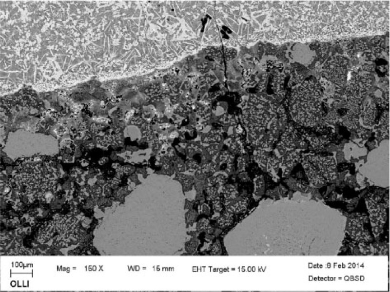
Slag interface of 9.5 mm thick brick sleeve after 30 min immersion in 29.1%Cu DtoB slag at 1350°C
The basic environment of the refractory and a small drop of temperature caused metallic copper to precipitate from the slag within the refractory sleeve; its fraction in the filled pores of the magnesia grains was significant. There was also a dense layer of delafossite crystals next to the refractory sleeve in case of the thicker brick sleeve (see Figs. 10 and 11).
Initial signs of slag reactions and penetration to cooled 9.5 mm thick brick: copper (white) has precipitated from slag; large magnetite crystals (grey) next to cold face of freeze lining are coated with delafossite (light grey) and form also needle-like crystals of its own
A simplified heat transfer model for the cold finger–sleeve–slag system (cylindrical geometry) was constructed using the HSC Chemistry and its Heat Loss module (Roine, 2009). The average heat flows of 0.35 and 0.30 kW measured in the water side were used in the calculations for 1.5 and 9.5 mm refractory sleeves respectively. The geometry included an immersion depth of 25 mm in the slag in both cases. The spherical bottom of the cold finger and its heat flux were neglected in the model calculations. The thermal conductivity of the freeze lining was estimated in an earlier study as 6.0 W m− 1 K− 1 (Jansson et al., 2013). Properties of a molten metal (Bi) were used to mimic the high copper DtoB slag. The refractory sleeve properties were based on an older brick quality by Radex, DB605-13 taken from the HSC property database, instead of the used Radex OX-6.
As indicated by the calculated temperature profile inside the freeze lining and refractory brick sleeve, the largest temperature drop between the molten slag and cooling water occurs in the air gap between the sleeve and water cooled steel probe. The drop in temperature over the air gap is 800–900°C in the cases with 9.5 and 1.5 mm sleeve respectively. Temperature drop through the refractory sleeve is only from ∼50 to 200°C, depending on its thickness. The outer, hot face temperatures of the freeze lining ∼1140°C, depicted by the profiles in Fig. 12, are calculated values only, based on the estimated total heat flows, dimensions of the probe and freeze lining and the thermal conductivities of the materials.
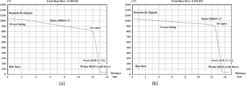
Estimated temperature profiles of freeze lining growth experiments with two refractory sleeve thicknesses of a 9.5 and b 1.5 mm in copper rich direct to blister slag
The above feature is specific to an insulator coated cooling system. As pointed out already earlier in the heat transfer analysis of finger coolers (Takasu et al., 2000), the insulation keeps the refractory lining temperature on the cooling elements high. It thus allows deep penetration of the molten slag into the open porosity of the refractory lining at the moment of slag contact.
The mechanism of freeze lining growth depends on the cooling and solidification rates of the slag on the refractory wall. The results of present study indicate the importance of a refractory lining assembly of the water cooled metal surface. It contributes to the formation of a new heat transfer system compared to a direct contact of molten slag. The cold face temperature of the freeze lining will be significantly higher in the case of the intermediate ceramic refractory layer, even if its (remaining) thickness is only a few millimeters. The cooling rate and thus microstructure generated in the freeze lining are modified compared to the cases of uncovered cooling elements. How this affects the stability and thermal properties of the freeze lining is unknown.
The heat transfer through a refractory coated cooling element is dominated by the air gap between the metal surface and the ceramic refractory, generated by their different coefficients of thermal expansion. It causes a temperature drop of several hundreds of degrees between the ceramic refractory and the water cooled metal surface. Thus, average temperature of the refractory lining on a cooling element is high and in most practical cases above 500°C. This feature affects the ability of the slag to stay molten in the open porosity of the refractory layer and allows its quick infiltration into the pore system. As a consequence, the contact surface of the molten slag with the refractory material is enlarged, allowing chemical interactions and ion exchange between the slag and the refractory minerals. At high oxygen pressures, the interactions are intensified by a low temperature oxide melt emerging above

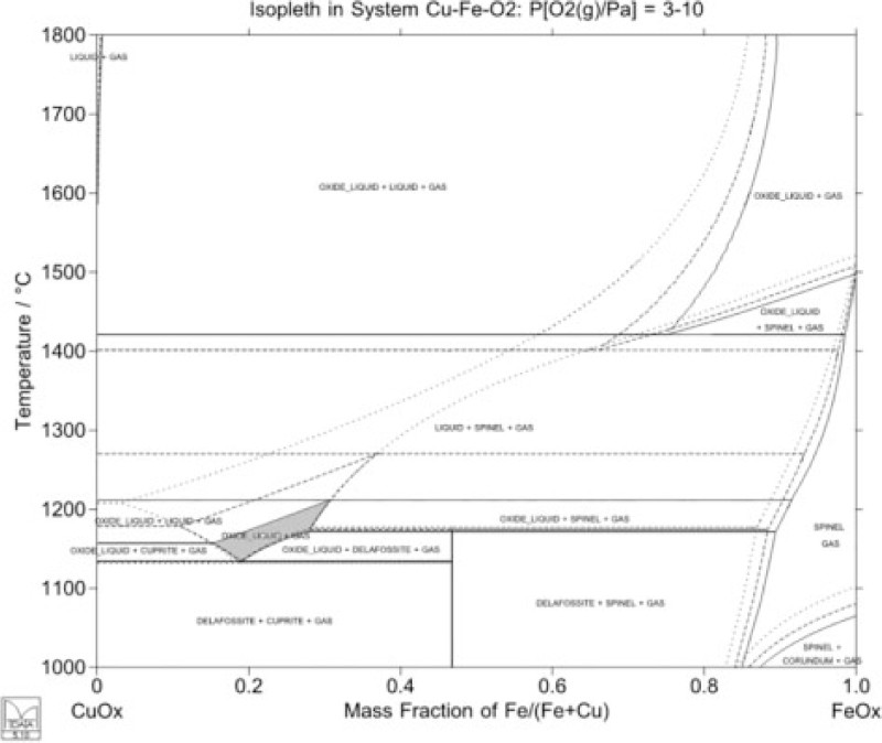
Stabilisation of low temperature slag melt (grey) at high oxygen activities in Cu–Fe–O system at 1130–1200°C; isopleths calculated at constant oxygen pressures by MTDATA and Mtox database: — 3 Pa, — 5 Pa and ···· 10 Pa
In this case, the only signs of ion exchange in the MagChrom refractory were traces of magnesium ferrite grains at the slag/refractory interface, identified by XRD and EDS, and by contrast differences on the magnesia grains, indicating diffusion of iron in them. No reactions of copper were, however, detected in the EDS observations in the periclase grains. The moderate reactivity of high fired magnesia against DtoB slags with an unusually high copper (oxide) concentration is also indicated by the very thin reaction zone observed in the dense MgO crucibles used for the DtoB slags in this study.
The refractory–slag reactions in many studies dealing with comparisons of various brick grades and their resistance against infiltration and chemical dissolution are problematic to interpret, as most experiments in the literature have been carried out in air atmosphere with oxygen pressure

Conclusion
The current results present the first freeze lining growth observations with a novel cold finger technique including a refractory sleeve. An air gap, due to tolerances needed in the assembly and differences in coefficients of thermal expansion, between the water cooled metal surface and the ceramic refractory sleeve, was separating the molten slag and cooled steel surface in the experiments. The results indicate a great effect of the stagnant air gap on the heat transfer rate and thus on the structural features of the forming freeze lining layer. The temperature drop from the molten smelting slag to the cold face of the solidified slag is reduced by about the factor of 10 from the case where the freeze lining is formed directly on the water cooled metal surface. This condition affects the microstructure, refractoriness and the thickness of the protective slag layer on the cooled furnace ‘wall’ represented by the cooling finger–refractory sleeve system.
The microstructure of the freeze lining forming on an insulating layer on the water cooled metallic cooling element does not have the typical, predominantly glassy or microcrystalline cold face microstructure. Thus, its impact to the thermal conductivity of the freeze lining may be less pronounced compared with quickly cooled linings, formed directly on the water cooled metal surface. At high oxygen pressures, above

The ceramic interface on the water cooled metal surface rises the cold face temperature of the forming freeze lining to temperatures close to 800°C, as estimated by the simplified heat transfer simulation of the laboratory scale experimental device used in the current experiments. Owing to good wetting between molten slags and ceramic refractory materials, the formed bond between the freeze lining and refractory is obviously strong, and peeling off in severe temperature shocks may take place along the infiltrated boundary of the refractory lining. This means that 0.3–0.5 mm of the cooled refractory wall thickness may be lost in one single incident.
Based on the current observations about the effect of high copper iron silicate slag on the chemical corrosion of high fired direct bonded MagChrom refractories, copper oxides in the slag were not the most aggressive component of the DtoB slag. The quick impregnation of the fluid copper rich slag into the open porosity of the brick even in the cooled furnace wall extended several 100 μm in the initial contact with the slag. This will modify the physical properties of the surface of the refractory material on the hot face, and increase thermal conductivity as well as impair its strength against thermal shocks.
Footnotes
Acknowledgements
The authors are indebted to Outotec (Finland) for the permission of publishing results of this experimental research, funding the project as well as providing the key materials used in the investigation, as well as the chemical analyses.