
Abstract
Deep Mining 2012 is the sixth in a series of international seminars on deep and high stress mining which began with a seminar held in Perth in November 2002, almost a decade ago. The early announcements for this seminar listed 10 seminar themes. This paper seeks to make contributions to the discussion of progress made in four of these themes – geomechanics risks, risk assessment and management, rock behaviour under high stress, and numerical modelling – largely, but not only, through a review of the papers published in the proceedings of the five previous seminars. Particular emphasis is placed on the risks associated with the new generation of block and panel caving operations or ‘super caves’. Some remaining challenges in the four theme areas discussed are also identified.
Keywords
Introduction
Deep Mining 2012 is the sixth in a series of international seminars on deep and high stress mining which began with a seminar held in Perth in November 2002, almost a decade ago. The writer has not attended, or contributed to, any of the five previous seminars in this series, and so approaches the task of preparing this keynote paper from the perspective of a newcomer to these Deep and High Stress Mining seminars.
The early announcements for this seminar listed 10 seminar themes: geomechanics risks, financial risks, case studies, numerical modelling, rock behaviour under high stress, rockburst and seismicity monitoring, ground support, risk assessment and management, ventilation and blasting. This paper seeks to make contributions to the discussion of progress made in four of these themes: geomechanics risks, risk assessment and management, rock behaviour under high stress, and numerical modelling – largely, but not only, through a review of the papers published in the proceedings of the five previous seminars. Some remaining challenges in these areas are also identified. For the reasons to be outlined in the section on ‘Deep and high stress mining methods’, this paper will consider some methods of deep and high stress mining more than others.
Deep and high stress mining methods
The papers presented to the previous seminars have dealt with a wide range of generic underground mining methods, including:
deep tabular orebody mining (including longwall methods, remnant mining and the mining of shaft pillars)
longwall coal mining
block and panel caving
sublevel caving
underhand and overhand cut-and-fill and drift-and-fill stoping
bench-and-fill stoping
sublevel and long hole open stoping (including narrow vein methods such as long hole retreat or Avoca and modified Avoca methods)
room-and-pillar mining
variants of these methods, including their use in pillar recovery and sill pillar mining.
Over a long career, the writer has had some association with mines using all of these methods. However, during the 10 years in which the seminar series has been in operation, his major mining interest and experience has been in block and panel caving (Brown, 2007a,b). He also has a long-standing association with metalliferous mining by drift-and-fill and bench-and-fill methods (Been et al., 2002; Brown, 1999). The observations drawn from the writer's own experience will deal mainly with these mining methods. Any reference to other mining methods, particularly the mining of deep, tabular orebodies in South Africa, will be through reference to papers published in the proceedings of this seminar series and elsewhere.
Geomechanics risks
Definitions
The first question to be answered is how do we define a geomechanics risk? The literature on risk analysis, assessment and management contains a range of definitions of risk and associated terms. Here, the definitions given by AS/NZS ISO 31000: 2009 (Standards Australia, 2009) will be used. It should be noted that these definitions differ, sometimes marginally and sometimes significantly, from those used in some earlier publications, including those by the writer (Summers, 2000; Brown, 2007a; Brown and Booth, 2009). Standards Australia (2009) defines risk as ‘the effect of uncertainty on objectives’ and a risk source as an ‘element which alone or in combination has the potential to give rise to a risk’. In some earlier accounts, a risk source appears to have been referred to as a hazard, defined in the previous Australian Standard as ‘a source of potential harm’ (Standards Australia, 2004). This term is not defined in AS/NZS ISO 31000:2009. The level of risk is defined as the ‘magnitude of a risk or combination of risks, expressed in terms of the combination of consequences and their likelihood’. This definition allows for the common practice in the mining industry and elsewhere of quantifying risk as the product of the likelihood of the occurrence of an event and the consequences of that event (Brown, 2007a; Steffen et al., 2008; Brown and Booth, 2009). The Standards Australia (2009) definition of an event as an ‘occurrence or change of a particular set of circumstances’ is consistent with this usage. The consequence of an event is the ‘outcome of an event affecting objectives’ and likelihood is the ‘chance that something will happen’ (Standards Australia, 2009).
A risk evaluation process as applied to stope design is shown in Fig. 1. The left hand column of Fig. 1 identifies possible causes of stope failure. It is suggested that, in terms of the Standards Australia (2009) definitions, these occurrences are best described as events. Following an approach that is commonly adopted in the mining industry (Steffen et al., 2006; Tapia et al., 2007), in the central column risks are categorised in terms of consequences as being expected fatalities, expected economic loss, loss of production, probability of force majeure, industrial action and stakeholder resistance. The right hand column in Fig. 1 is concerned with the level of risk as defined by Standards Australia (2009). The question then remains as to what we mean by a geomechanics risk. For present purposes, and for consistency with the terminology used in AS/NZS ISO 31000:2009, a geomechanics risk will be taken to be a geomechanics-related risk source, hazard or uncertainty that gives rise to events of the types listed in the left-hand column of Fig. 1, not only in stopes, but in other underground mining excavations as well. This ‘definition’ will be interpreted rather liberally in that which follows.
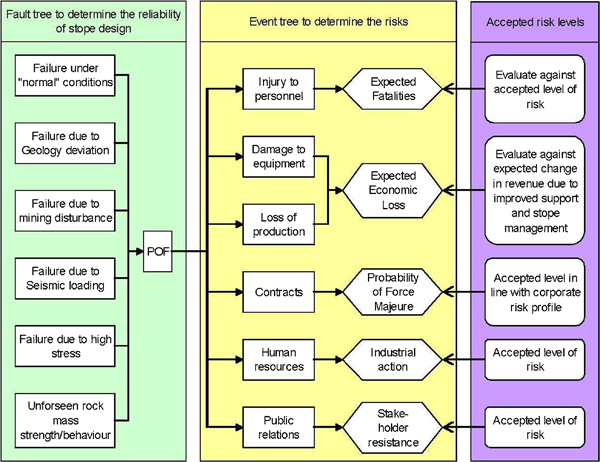
Risk evaluation process (Stacey et al., 2006)
Generic geomechanics risks in deep and high stress mining
The nature of the uncertainty and the errors that provide the sources of geomechanics risk in geotechnical engineering more broadly have been discussed widely in the literature. For example, Einstein and Baecher (1983) classified the sources of uncertainty as:
inherent spatial and temporal variability
measurement errors (systematic or random)
model uncertainty
load uncertainty
omissions.
Baecher and Christian (2003) described these sources of uncertainty as being aleatory (randomness) or epistemic (lack of knowledge). Similarly, in discussing variability in soil properties, Phoon and Kulhawy (1999) suggested that there are three primary sources of geotechnical uncertainty – inherent variability, measurement error, and transformation (or model) uncertainty. In discussing risk in a general engineering context, in common with Baecher and Christian (2003) and others, Brown (2007a) concluded that there are two general types of uncertainty:
what we know we don't know, or parameter uncertainty
what we don't know we don't know, or conceptual uncertainty.
Recently, Hadjigeorgiou and Harrison (2011) provided a valuable account of uncertainty and the sources of error in rock engineering. In discussing the use of rock mass classification schemes in the design of underground excavations they identify two groups of errors. The first group consists of errors intrinsic to the classification scheme used, including errors of omission, errors of superfluousness, and errors of taxonomy associated with the requirement to select a particular classification rating value for a geomechanical property. The second group of errors are associated with implementation, and include errors of circumstance, errors of convenience, errors of ignoring variability, and errors of ignoring uncertainty.
Clearly, deep and high stress mining is susceptible to the geomechanics risks or hazards associated with uncertainties and errors of these several types, as well as to other categories of risk (Sweeney and Scoble, 2006). It should be possible to develop a detailed (if not comprehensive) list of these risks or hazards and their sources similar to that developed for open pit slopes by Brown and Booth (2009) who identified geology, structure, rock mass, hydrogeology and geotechnical model hazards or risks. In discussing the management of geotechnical risks in mining projects, Hebblewhite (2003) suggested that the risks within a mining operation can be categorised as occupying three levels or superimposed layers:
Level 1 – day-to-day operational risks managed through mechanisms such as training and Safe Operating Procedures.
Level 2 – specific site or mining condition-related risks managed through management initiatives such as Ground Control Management Plans.
Level 3 – core risks associated with the mining method or system.
Hebblewhite (2003) then listed and discussed the core risks associated with block caving, longwall mining, open stoping and room-and-pillar mining, based on the classification of rock mass response to underground mining suggested by Brady and Brown (2004).
The following partial list of generic geomechanics risks and/or risk sources (mainly Hebblewhite's Level 2 and 3 risks) that may be encountered in deep and high stress mining includes several issues referred to in the papers presented to previous seminars in this series (geomechanics risks that are specific to caving methods of mining will be discussed in the section on ‘Geomechanics risks in block and panel caving’):
geological boundaries which may be unknown or inadequately or incorrectly defined (Falmagne and Frenette, 2006)
geological structures including dykes, faults and shear zones, possibly containing low shear strength minerals (Guilfoyle et al., 2006; O'Connor et al., 2010)
several aspects of site hydrogeology
orientations, spacings, persistences and shear strengths of the joint sets in the rock mass (Gumede and Stacey, 2007; Stacey and Gumede, 2007)
values and distributions of the compressive strengths and elastic properties of the rock materials (Kaiser et al., 2010; Valley et al., 2010b, c)
brittle and burst-prone rock (Falmagne and Frenette, 2006)
the effects of heterogeneity and anisotropy, e.g. foliation, on the mechanical properties of the rock materials (Valley et al., 2010c)
rock mass classification values and their use in estimating rock mass strengths
rock and rock mass strength criteria (Kaiser et al., 2010; Valley et al., 2011)
(lack of) knowledge of the behaviour of the rock and rock mass under high stress (Kaiser et al., 2010; Valley et al., 2011) (see the section on ‘Rock behaviour under high stress’)
weathered, altered or otherwise weakened rock (Mercier–Langevin and Turcotte, 2006; Potvin and Slade, 2006; Mercier–Langevin, 2010)
estimates of the pre-mining stresses and the effects of geological structures and rock mass anisotropy and heterogeneity on those estimates (Thin et al., 2006; Dight and Dyskin, 2007; Valley et al., 2010b)
high horizontal in situ stress fields, even at relatively shallow depths (Barrett and Player, 2002; Villaescusa et al., 2002)
the relationship of induced stress to rock and rock mass strength, including in squeezing ground (Mercier–Langevin and Hadjigeorgiou, 2010)
the treatment of variability in the stresses and strengths using probabilistic methods (Reusch and Beck, 2007; Valley et al., 2010b)
natural seismicity
mining-induced seismicity including the effects of geological structures (Li et al., 2002; McGill, 2004; Morrison et al., 2002; Beck et al., 2007; Orrego et al., 2010; Yao and Moreau–Verlan, 2010)
excavation and mining layout and sequencing (Beck and Sandy, 2002; Mercier–Langevin and Turcotte, 2006; Pretorius, 2006)
mining highly-stressed remnants and shaft, rib, crown, sill and waste pillars (Mikula and Lee, 2002; Cockram et al., 2004; Kiboko et al., 2004; Pretorius, 2006; Simser, 2006; Andrieux et al., 2010)
mining under fill, including in sill pillars (Brown, 1999; Simser, 2006)
mining into or under previously mined or caved ground (Sharrock et al., 2002)
model formulation, numerical analysis and the interpretation of results (see the section on ‘Numerical modelling’)
pillar strength estimation methodologies (Board et al., 2007; Kaiser et al., 2010)
blasting effects
ground support performance (Swan et al., 2006; Simser, 2007)
fill and fill barricade performance.
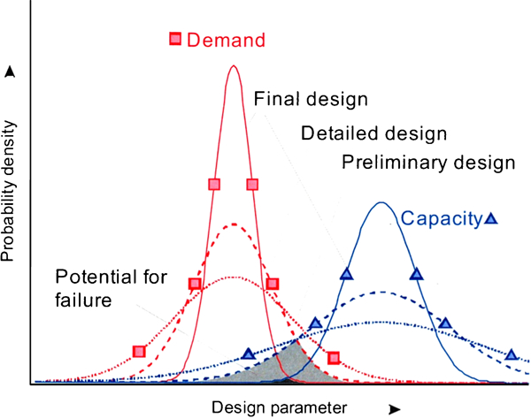
Clearly, it will never be possible to carry out enough geological, geotechnical and hydrogeological investigation and design analysis to enable geomechanics risks of this wide range of types to be fully accounted for in the planning stages of a mining project. However, as a project proceeds through the various stages from concept to detailed design and implementation, the level of uncertainty and risk associated with many of the sources of geomechanics risk identified previously can be expected to be reduced in the manner illustrated in Fig. 2. In mining, it might be more usual to describe the stages of a project as conceptual or scoping, pre-feasibility, feasibility, design, implementation or operation, and closure, although many mining companies now use their own terminologies for these various stages. In practice, risk assessment and risk management approaches are used to minimise the levels of risk and to manage the residual risks (see the section on ‘Risk assessment and management’).
Geomechanics risks in block and panel caving
Over the last 20 years, there has been increased interest internationally in the use of large-scale (or mass mining) block and panel caving methods of underground mining. Indeed, there has been a trend for some companies to plan, and in several cases to bring into production successfully, a transition from large-scale open pit to underground cave mining methods (Moss et al., 2004; Arancibia et al., 2008; Glazer and Townsend, 2010; Marshall, 2011). There have also been transitions from open pit to sublevel caving (Singh et al., 2010) and from sublevel caving to block caving (Manca and Dunstan, 2008). The following discussion of modern, large-scale block and panel caving is based on that given by Brown (2007b).
Figure 3 shows schematics illustrating the essential features of block caving, and a conceptual model of the stress caving mechanism likely to apply in modern, deep block and panel caving mines.
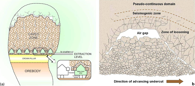
a the essential features of block caving
Historically, block caving was used for relatively shallow, massive, low strength, and usually low grade, orebodies which produced fine fragmentation. In what is now the usual case in which mining is mechanised, the low strength of the rock mass can place limitations on the practicable sizes of the extraction level excavations and of the equipment that can be used. There is now a tendency for block and panel caving to be used in stronger orebodies which produce coarser fragmentation than did the traditional applications of block caving. This enables more widely-spaced drawpoints and larger, more productive items of equipment to be used. However, there are the dangers that the fragmentation may be too coarse to be handled by the drawpoints or the load–haul–dump equipment, and that caving may become stalled in these stronger orebodies, particularly those with restricted footprints.
In the new generation of ‘super caves’, block and panel caving are being applied to generally, but not necessarily, stronger orebodies, to deeper and sometimes ‘blind’ orebodies subject to higher stresses, to lower grade orebodies, and to greater caving block heights than has previously been the case. Production rates of well in excess of 100 000 t of ore per day are being planned in several cases.
Block and panel caving are low cost mining methods that are capable of automation to produce an underground ‘rock factory’. However, they are capital intensive requiring considerable investment in infrastructure and development before production can commence. They are relatively inflexible in that, once mining has started, a change to another underground method is difficult to achieve economically. This places great onus on ‘getting it right’ when a caving project is being investigated and planned. In addition to a range of generic and caving-specific geomechanics risks, the extremely large-scale or ‘super cave’ projects now being planned and implemented involve a range of engineering and management challenges which include:
their massive scales, involving project management challenges
the very long lead times from the start of investigations until the commencement of production – up to 20 years in some cases
the high capital costs, generally in the order of a few billion dollars
high in situ rock temperatures at depth and the associated refrigeration and ventilation requirements. At the Resolution Copper Mining project in Arizona, USA, for example, the in situ rock temperatures at the proposed mining depth of 2200 m are ∼80°C (Pascoe et al., 2008)
the large amounts of development required and its generally long design life
the desirability from a health and safety perspective of no-entry mining and of the automation of production, and possibly development, processes
water and environmental management – ever present concerns in major mining projects
underground communications and control systems.
The geomechanics-related risks and the application of risk management approaches to block and panel cave mining have been discussed in some detail by Brown (2007a,b) as well as by a number of other authors. Generally, these risks may be identified within the context of several major issues:
Caveability: will the orebody cave satisfactorily?
Caving mechanics and performance (including cave initiation by undercutting and continued cave propagation): will the cave propagate at an acceptable rate and in a controlled manner spatially? Can the process be stopped and started once initiated (Marshall, 2011)? Note that the stress caving mechanism illustrated in Fig. 3b produces microseismic events that can be recorded to monitor the progress of caving (Duplancic and Brady, 1999; Beck et al., 2006b; Glazer and Townsend, 2010).
Fragmentation: will the fragmentation produced naturally at the draw points be neither too coarse nor too fine?
Excavation stability: will the undercut and extraction level excavations, in particular, remain stable throughout their design lives? In many cases, there is a major risk of damaging rock bursting (Beck et al., 2007).
Major operational hazards: is there a risk of major collapses, rockbursts, air blasts, and/or mud, slurry and water inflows?
Surface subsidence: can we predict the nature, extent and development of surface subsidence and its impact on natural surface features and surface installations?
Chitombo (2010) has succinctly summarised some of the major geomechanics-related challenges or risks that may threaten the future viability of cave mining as:
‘not being able to achieve continuous caving resulting in cave stalling or slow caving rates;
differential cave propagation due to the presence of different geological lithologies;
seismicity caused by unfavourable undercutting practices;
early dilution or waste ingress and accelerated fines migration containing waste;
structural collapses and instabilities due to mining of large panel widths; and
extraction level instabilities due to poor undercutting practice, the presence of remnant pillars or compaction of caved materials (as) a consequence of poor draw practices.’
Risk assessment and management
The last 20 years or so have seen the relatively rapid development and application of risk assessment and management methods to evaluate and manage the geomechanics and other risks associated with mining projects and operations. Early applications of risk concepts to underground mining geomechanics evaluated the influence of parameter and other input variability on the probability of failure using the general approach illustrated in Fig. 2 (McCracken and Stacey, 1989; Tyler et al., 1991; Pine, 1992). The consideration of the cost implications of the calculated probabilities of failure, often using cost-benefit analysis, followed slightly later (Brummer et al., 1993; Suorineni et al., 1995; Diederichs and Kaiser, 1996; Horsley and Medhurst, 2000). The application of probability, risk, reliability and capacity and demand concepts to other areas of geotechnical engineering, including open pit mine slope stability, had preceded these developments by a few years (McMahon, 1975; Priest and Brown, 1983; Whitman, 1984; Harr, 1987).
The Australian mining industry has used risk-based management techniques since the 1980s (Hebblewhite, 2009). Risk-based underground mining regulations were introduced in Australia from the early 1990s. In mid-2011, Safe Work Australia published draft national risk-based model Work Health and Safety Regulations and Codes of Practice for Ground Control in Open Pit and Underground Mines. In South Africa, an industry Code of Practice requires that a risk assessment be carried out before any new support system is introduced (Stacey et al., 2006).
To the best of the writer's knowledge, detailed risk assessment and management approaches of the type illustrated in Fig. 1 were applied to open pit mine slope stability before they were applied to the wider range of underground mining geomechanics risks. Examples of open pit slope stability applications are given by Brown and Booth (2009), Calderón and Tapia (2006), Steffen (1997), Steffen et al. (2006, 2008), Tapia et al. (2007) and Terbrugge et al. (2006). This difference may be accounted for, at least in part, by the fact that the geomechanics risks associated with a given underground mining project or operation, including cases of deep and high stress mining, are likely to be more wide-ranging and varied than those associated with bench, inter-ramp and overall slope stability in a given open pit mine.
As in Fig. 1, risk assessment and management approaches in underground mining, especially quantitative risk assessment approaches, are more likely to be applied to particular aspects of mining or mining risk, or to components of the overall mine structure such as shafts, stopes, ore or rock passes, ventilation raises, and crusher chambers, than to the mining operation as a whole (Cockram et al., 2004; Dunn, 2004; Logan and Tyler, 2004; Joughin and Stacey, 2005; Stacey and Gumede, 2007). It would appear to the writer that there is scope to further develop and apply some of these approaches. As discussed in several papers to this series of international seminars, risk-based approaches are widely used for the assessment and management of seismic risk (Hudyma et al., 2006; Pretorius, 2006; Durrheim et al., 2007).
Risk assessment forms an important part of the conceptual, pre-feasibility and feasibility studies of potential mining projects, whether they be new developments on green field sites or represent expansions of, or changes to, existing operations. It allows significant, and sometimes critical, risks to be identified during the planning stages and risk management options or control measures to be devised and the residual risks evaluated. The writer has had experience of cases in which the results of this process were critical to decisions taken at senior management and Board levels as to whether or not to proceed with a project. Risk management plans are also an essential feature of modern operations. Figure 4 shows the risk management decision-making process adopted by Newcrest Mining's Cadia Valley Operations. This approach provided the basis for the development of a range of operational risk and hazard management plans including the air inrush hazard management plan for the Ridgeway Mine discussed by Logan and Tyler (2004).
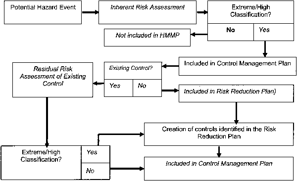
An operational risk management decision-making process (Brown and Booth, 2009,
Rock behaviour under high stress
Background
The behaviour of rock under elevated confining pressure has been investigated in standard triaxial compression tests (with σ1>σ2 = σ3, where σ1, σ2 and σ3 are the principal stresses) for more than 100 years since the pioneering work of von Kármán (1911) who tested Carrara marble at confining pressures of up to 326 MPa. Mogi (2007) summarises the results of standard triaxial tests on a wide range of carbonate and silicate rocks tested at confining pressures of up to 500 MPa. The treatment of this subject given in the standard text books (Brady and Brown, 2004; Jaeger et al., 2007) would suggest that it is reasonably well, if not fully, understood. However, a number of recent developments, including some made at this series of Deep and High Stress Mining seminars, suggest that the behaviour of rock in the context of deep and high stress mining may not be as well understood as is often supposed. For purposes of illustration, this discussion will focus mainly on the behaviour of rock material rather than on the more complex behaviour of in situ rock masses.
Applicability of standard strength criteria
Several peak strength criteria and constitutive laws have been developed for rock and used in rock engineering design analyses. Currently, perhaps the two most widely used strength criteria are the Mohr–Coulomb and the Hoek–Brown criteria (Brady and Brown, 2004). The classic Mohr–Coulomb peak strength criterion consisting of two independent cohesive and frictional components does not provide a realistic representation of the progressive fracture and breakdown of rock under stress. The Hoek–Brown criterion is widely applied to jointed rock masses but may also be applied to intact rock. In fact, much more data for intact rock than for rock masses were used in its original development by Hoek and Brown (1980). One of the acknowledged deficiencies of both the Mohr–Coulomb and Hoek–Brown criteria is that they do not allow for the influence of the intermediate principal stress on peak strength. Several adaptations of these criteria and new criteria that seek to overcome this deficiency have been proposed. As discussed in some detail previously, the writer considers that the Hoek–Brown criterion has often been applied and extended to circumstances for which its use was not originally intended (Brown, 2008).
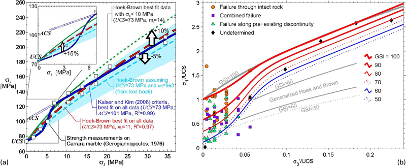
Aspects of the Hoek–Brown criterion that have received considerable attention from Diederichs, Kaiser, Martin and their co-workers in Canada, over the last 15 years or so, are the difficulties associated with its use in modelling brittle spalling failures in strong rock around underground excavations and in estimating rock strength under high confinement (Diederichs et al., 2004; Kaiser and Kim, 2008; Martin and Christiansson, 2009; Kaiser et al., 2010; Bahrani et al., 2011; Valley et al., 2011). As argued by Kaiser et al. (2010) and subsequently by Bahrani et al. (2011) and Valley et al. (2011), rock and rock mass strengths under high confinement may be higher than those derived from standard approaches. They suggest that the mechanics of the fracturing of rock under low and high confinement could differ significantly, and that the constant rock mass degradation approach used in the Hoek–Brown criterion could be flawed. They propose a modified Hoek–Brown failure criterion which incorporates a confinement-dependent value of the Geotechnical Strength Index and produces a sigmoidal peak strength curve. Figure 5 shows a further modification of this criterion fitted to experimental data for Carrara marble and a quartzite (Valley et al., 2011). In these cases, the standard Hoek–Brown criterion with a constant value of the parameter mi can over-estimate rock and rock mass strengths at low confining pressures where tensile or extensional mechanisms predominate, and under-estimate them at high confinement where shear failure mechanisms operate. Reasonable fits to a range of experimental data can also be obtained using bi- or tri-linear envelopes or a generalised Hoek–Brown envelope with a high value of mi and a low value of the Hoek–Brown parameter a. These findings have obvious implications for the behaviour of deep and high stress mining excavations.
Another, possibly less significant, reason why standard testing methods and strength criteria may underestimate the strength of rock around deep excavations under high stress is that on the boundary of an underground excavation where the minor principal stress is either zero or very small, the rock is in a state of approximately biaxial compression with the value of the intermediate principal stress σ2, which generally acts along the axis of the excavation, being non-negligible when compared to the major principal stress σ1, which generally acts tangentially at the excavation boundary. Recent studies by Yun et al. (2010, 2011) have shown that, depending on the stress path followed and the σ2/σ1 ratio used in the test, the compressive strength of granite in biaxial compression can be more than 50% greater than the uniaxial compressive strength σc, of similar sized specimens of the same rock. Brown (1974) obtained a similar result for marble but with a lesser increase over the standard σc value.
Influence of core damage
An important issue that is not always fully recognised, or taken into account when considering rock behaviour in the context of deep and high stress mining, is the influence of stress relief on the cores extracted by drilling and tested in order to establish rock material properties and strength criteria. In fact, the influence of damage on the rock properties measured on cores recovered from relatively high stress environments has been studied by a number of investigators. Recently, Valley et al. (2010a) summarised a number of findings of Eberhardt et al. (1999), Lanaro et al. (2009), Martin and Stimpson (1994) and Watson et al. (2009) in the following way:
‘They (Martin and Stimpson, 1994; Eberhardt et al., 1999) showed that the UCS, Young's modulus and p-wave velocity measured on cores decrease and Poisson's ratio increases as samples are obtained from rock at increasing depth and consequently increasing in situ stresses. They suggest that these effects are caused by increasing microcracking with depth. This is also supported by the strong non-linearity of stress versus volumetric strain from damaged samples, reflecting higher volume of closing micro-cracks at the early stage of loading. Similar behaviour was also observed on samples taken from deep mines in South Africa (Watson et al., 2009). Crack count using Scanning Electron Microscope (SEM) analyses support that samples from depth contain larger amounts of microcracks. Lanaro et al. (2009) reported a strong negative correlation between sample strength and measured in situ strength and explained this observation by sample disturbance.’
As have others before them (Corthésy and Leite, 2008; Matsuki et al., 2004), Valley et al. (2010a) carried out a series of numerical analyses to simulate the drilling process and its effect on the recovered core. Their results suggest that, as the drilling progresses and the induced stress reaches a particular threshold, tensile yielding initiates from the outer edge of the core and propagates towards the centre of the core when the bit passes the point in question. However, while extensive yielding or damage may be generated in the core, no damage is produced in the borehole wall at the simulated stress level. This finding has important implications for a number of stress measurement methods and for the analysis of excavation stability using intact rock strengths determined from laboratory tests on recovered core.
The stress path followed by the recovered core and by the surrounding rock during the drilling and core recovery process can be expected to have a significant influence on the damage suffered by the core. As has been argued most cogently by Harrison and Hudson (2003), during the evolution of the final stress state to which the rock is subjected in any application, the failure locus may be reached before the anticipated failure state (assuming that the failure locus is known accurately), in which case failure will occur unexpectedly. In fact, the complete stress path defined as the variations in the magnitudes and orientations of the stress tensor components resulting from engineering-induced or natural changes, should be considered in sampling and testing and in design analyses for underground excavations. In many mining applications, including on and around the extraction levels of block and panel caving operations, the stress state and the stress path taken to reach that stress state can vary significantly during construction and operation.
Embrittlement at high confining pressures
In a series of recent papers, including some presented to previous Deep and High Stress Mining seminars, Tarasov and his co-authors have discussed the phenomenon of super brittleness in ‘hard’ rocks (Tarasov and Dyskin, 2005; Tarasov and Ortlepp, 2007; Tarasov and Randolph, 2007, 2008, 2011; Tarasov, 2008a,b, 2010, 2011). Received wisdom is that rocks tested in conventional triaxial compression show increasing ductility as the confining pressure σ3, increases. However, in this series of papers, Tarasov presents evidence from his own experimental investigations and from those of a number of other authors who have been concerned mainly with fault formation at depth, to suggest that after a critical confining pressure has been reached (σ3min(emb) in Fig. 6), brittleness may increase progressively within an embrittlement range. This concept may appear to be counter-intuitive, but the evidence for its existence under macroscopic shear rupture conditions in strong rocks seems compelling. This behaviour is not observed in what Tarasov (2010) refers to as ‘soft’ rocks, although he does not provide definitions of ‘hard’ and ‘soft’ in this context. Tarasov (2008a,b, 2010) proposes a new frictionless model within shear rupture zones that consist of segmented ‘domino’ or ‘book shelf’ structures to account for the super brittleness phenomenon. Although some ramifications of the mechanisms proposed by Tarasov and his co-authors have been observed in natural faulting and in shear zones associated with rockbursts in the deep level gold mines of South Africa (Tarasov and Ortlepp, 2007), it is probably unlikely that they will be encountered in deep and high stress mining more generally.
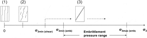
Typical variations in fracture pattern with confining pressure σ3 (Tarasov, 2010)
Numerical modelling
Numerical modelling in rock mechanics and rock engineering
The discussion to be presented in this section is a modified version of that given by Brown (2011) in discussing the progress made in rock mechanics over the last 50 years.
The application of numerical methods, specifically the finite element method (FEM), to rock engineering began in the early to mid-1960s. Since that time, the development and application of numerical methods of analysis has been a major feature of rock mechanics and rock engineering research and practice. A comprehensive review of the formulation of numerical methods and their application in rock mechanics and rock engineering is given by Jing (2003). Jing's paper contains no less than 774 references to the published literature in the field to 2003, but obviously does not deal with more recent developments.
The main numerical methods were developed originally for continuum applications but, from the 1960s, were adapted to allow for the discontinuous nature of rock masses (Goodman et al., 1968; Wittke, 1977), often treating them as equivalent continua. Importantly, specific discontinuum methods of numerical analysis have been developed. In rock mechanics and rock engineering, these various methods have been applied mainly to stress and deformation analyses, but they have also been applied to the modelling of fracture processes and of fluid flow and heat transfer in rock masses. Following Jing (2003), the numerical methods that have been developed or adapted for rock mechanics and rock engineering applications may be classified as:
FEM and related methods, including meshless methods (Goodman et al., 1968; Wittke, 1977, 1990; Zienkiewicz, 1977; Beck et al., 2009, 2010).
finite difference methods (FDMs) including the finite volume approach, applied perhaps most notably in the well-known FLAC series of codes (Hart et al., 2008; Itasca, 2011; Sainsbury et al., 2011).
boundary element methods (BEMs) using direct and indirect, including displacement discontinuity, formulations (Brady, 1979, 1987; Crouch and Starfield, 1983; Beer and Watson, 1992).
discrete element methods (DEM) (Jing and Stephansson, 2007) including the explicit or Distinct Element Method (Cundall, 1971, 1987; Itasca, 2011), the implicit or discontinuous deformation analysis method (Shi and Goodman, 1985; Ma, 2011), key block theory (Goodman and Shi, 1985), DEM formulations for particle systems including bonded particle systems (Potyondy and Cundall, 2004), and quasi-static and dynamic lattice network models (Cundall and Damjanac, 2009; Cundall, 2011).
hybrid or linked methods of a number of types (FEM/BEM, DEM/BEM, DEM/FEM) (Lorig and Brady, 1982; Elsworth, 1986; Brady, 1987; Beer and Watson, 1992).
discrete fracture network-based methods which may be combined with a number of the other methods (Pine et al., 2006; Beck et al., 2009; Rogers et al., 2010).
coupled hydro-mechanical (Beck et al., 2010) and thermo-hydro-mechanical models (Detournay, 1995; Stephansson et al., 1996; Hudson et al., 2001).
inverse solution methods as used in back analysis in rock engineering (Gioda and Sakurai, 1987; Sakurai, 1993).
Despite the significant advances that have been made, it must be recognised that the successful application of numerical methods in rock engineering design analyses depends to a great extent on the geotechnical models, the constitutive models and the boundary conditions developed from the site characterisation data. Because of the difficulty of defining some of the input data deterministically, probabilistic or stochastic methods are often used to represent the rock mass geometry, the mechanical properties of rocks and rock masses, and in the analyses themselves. When formal probabilistic or stochastic methods are not used, a range of input data may be used in sensitivity studies. As Starfield and Cundall (1988) pointed out, rock mechanics problems are data-limited and so cannot be modelled unambiguously.
As the numerical methods of design analysis outlined here were developed, high levels of expertise in the numerical methods themselves, and in their application in rock mechanics and rock engineering, were developed by a number of individuals and groups internationally. However, it has been the writer's experience that, despite the vast range of knowledge and experience that is now available in this field, the application of these methods in engineering practice often suffers, because some analysts regard the computer codes used as ‘black boxes’ and pay insufficient attention to the mechanics of the problems concerned, the failure criteria used, the input data including rock and rock mass properties, and to the meaning or ‘believability’ of the results obtained. Furthermore, there is a tendency to disregard features of a problem that are not catered for specifically in the software selected or available for use. Although the paper was written more than 20 years ago, the writer considers that many of those seeking to use modern numerical methods in rock engineering design analyses should pay greater attention to the guidance provided by Starfield and Cundall (1988), especially their warning that numerical modelling is an aid to thought rather than a substitute for thinking.
Numerical modelling in deep and high stress mining
Serious consideration of the geomechanics problems associated with deep and high stress mining began before the advent of modern high-speed digital computers and the numerical modelling methods listed in the section on ‘Numerical modelling in rock mechanics and rock engineering’. For example, a significant programme of research on rock mechanics as applied to deep-level hard rock mining and the associated problem of rockbursts, was established in South Africa in 1953 (Hill, 1954, 1966). At around the same time, a similar problem was under investigation in the Kolar goldfield, India (Taylor, 1962–63). And as Morrison et al. (2002) discuss, rockbursting has been experienced and investigated in North American hard rock mines for more than 100 years.
In the South African programme of research into the phenomenon of rockbursting associated with the mining of deep, tabular or reef deposits, elastic stress and deformation analyses were originally carried out using closed-form solutions developed specifically for the purpose (Cook et al., 1966; Salamon, 1963, 1964, 1968). An electric resistance analogue approach to the solution of the complex equations involved was also developed (Salamon et al., 1964; Cook et al., 1966). Salamon's solutions for isotropic and transversely isotropic ground formed the basis of early calculations of energy release rates and excess shear stresses (Ryder and Jager, 2002). By the late 1960s, the MinSim program had been developed in assembly language (Plewman et al., 1969). Further development of two- and three-dimensional displacement discontinuity kernels (Crouch and Starfield, 1983) led to the development of successive versions of numerical modelling programs such as MINAP, MINF, DIGS and BESOL (Ryder and Jager, 2002).
A wide range of computer codes have been used in the numerical analyses reported in the papers presented to the Deep and High Stress Mining series of seminars. They include the range of displacement discontinuity and related programs introduced previously (MinSim, MINF, DIGS, BESOL), as well as FEM (ABAQUS, Phase2), BEM (Examine2D, Examine3D, Map3D, Map3D Fault-Slip), FDM (FLAC, FLAC3D) and DEM (3DEC, PFC3D) codes. The three-dimensional elastic boundary element code, Map3D, and its variants, is perhaps more widely represented in the papers than any other code, particularly in the papers from Australia and, to a lesser extent, South Africa. The most advanced numerical modelling reported in the series of proceedings includes that carried out by Beck et al. (2006a,b, 2007) and Reusch and Beck (2007) using the three-dimensional, non-linear, FEM code, ABAQUS, with continuum, discontinuum, strain softening and dilation modelling capability. These authors calculate values of dissipated plastic energy for use in the interpretation of their results.
Figure 7 shows an example of the modelled three-dimensional plastic strain at an early stage of extraction of a block cave. Differential growth in the damage zone around the cave and the effects of the regional structure are clearly evident. The mine was able to adjust the cave layout to optimise the effects of plastic strain (Beck et al., 2006b).
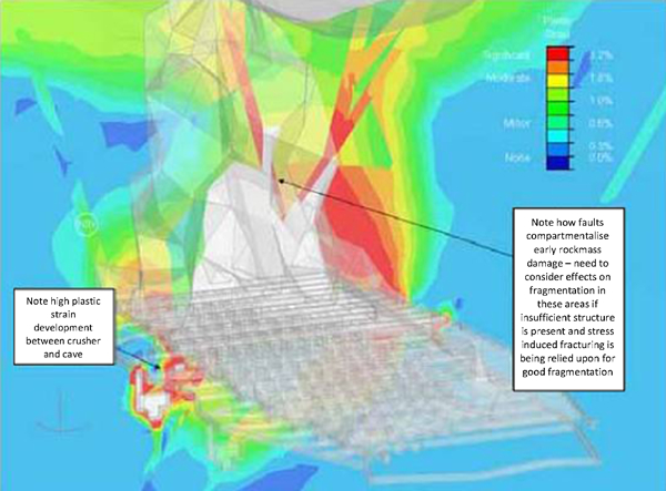
Example of modelled plastic strain at an early stage of the extraction of a block cave (Beck et al., 2006b)
Despite the power and adaptability of numerical modelling codes, and the wide range of numerical modelling expertise now available, as noted above, the warnings sounded by Starfield and Cundall (1988) still have to be borne in mind. In this series of seminars, Beck et al. (2006a), O'Connor et al. (2010) and Wiles (2007) have pointed to the need to use evidence-based model calibration in order to obtain reliable predictions. Valley et al. (2010b) have discussed the need to consider a range of uncertainties in modelling the behaviour of underground excavations. Reusch and Beck (2007) and Valley et al. (2010b) have used a point estimate method in preference to the more widely used Monte Carlo simulation method, in analysing the effects of parameter variability in FEM simulations. It has also been shown that the utility of numerical modelling programs can be enhanced by their integration with engineering design, mine planning and post-processing software (Spottiswoode, 2004; Maybee et al., 2006; O'Connor et al., 2010).
Further challenges
This paper has discussed only some of the risks and challenges faced by deep and high stress mining. For example, McCarthy (2002) suggested that the risks that must be addressed in feasibility studies for deep mining projects include:
increased geological risk due to sparse data density
increased capital risk due to the higher cost of establishing the mining operation
increased technical risk due to the challenging environment for materials handling, ventilation, services, employees and ground control.
Although the review given here of progress made under some of the themes of this seminar shows that significant advances have been made in understanding and practice, it is clear that the generic risks identified by McCarthy (2002) remain largely unresolved and have to be managed in the various stages of deep mining projects. The further challenges identified and discussed briefly here will concern only some of the geomechanics-related issues touched on earlier in this paper.
Many of the geomechanics risks and risk sources listed in the sections on ‘Generic geomechanics risks in deep and high stress mining’ and ‘Geomechanics risks in block and panel caving’ arise from inadequate (in several senses) geological, geotechnical and hydrogeological knowledge, even at the feasibility study and implementation stages of deep mining projects. In general, these inadequacies arise because of the inability to sample and investigate even very small percentages of the orebodies and the rock masses influenced by mining during the conceptual, pre-feasibility and feasibility stages of projects. Generally, access to the mining depth is difficult and expensive to obtain, so that the only information available often comes from geological and geotechnical drilling campaigns supported in some cases by geophysical surveys and geological interpretation. Even the construction of an 8·4 m diameter exploration shaft to a depth of approaching 2·2 km in the pre-feasibility stage of the Resolution Copper Project, Arizona, and the development of an exploration level with associated investigation and testing during the feasibility study stage, cannot be expected to provide the detailed information and answers required for fully-informed decision making (Brown, 2007b).
The following paragraphs identify and discuss briefly just some of the challenges remaining in this general area and in some of the areas discussed earlier in this paper.
Geological and geotechnical data collection and site characterisation
Many of the geomechanics risks and risk sources listed in the section on ‘Generic geomechanics risks in deep and high stress mining’ relate to the quantity and quality of the geological and geotechnical data collected and to their use in site characterisation. In particular, improved methods are required for identifying major geological structures (e.g. dykes, faults) ahead of mining, and for collecting the three-dimensional discontinuity geometry data, including fracture sizes and apertures, required in discrete fracture network modelling, particularly at depth. It is often said that we need to be able to see through the Earth or make the Earth transparent (Hood et al., 1999; Fairhurst, 2011). It is often further suggested that geophysical methods have the potential to provide this capability, but the writer must admit that he does not understand exactly how.
Estimation of pre-mining stress fields
The measurement, or perhaps more realistically, the estimation, of pre-mining stress fields provides essential inputs into numerical stress and deformation analyses of underground excavations, mining layouts and extraction scheduling. Quite often, attempts to measure the stress tensor at a number of points with a view to establishing the pre-mining stress field yield unsatisfactory results, not only because of measurement error, but also because of the inherent variability of the stress field resulting from, inter alia, variations in rock types and their mechanical properties and from the influence of structural features. As a result of his association with a number of large-scale and deep block and panel caving projects, in recent years the writer has become convinced of the value of studies of the type reported by Kloppenburg et al. (2010), Windsor (2009) and Windsor et al. (2006), in which the structural setting and kinematics of a mining district are analysed on an historical basis, and the observed structure, strain and stress are reconciled.
Understanding rock behaviour under high stress
Some recent advances in the understanding of rock behaviour under high stress were summarised in the section on ‘Rock behaviour under high stress’. It is clear from this summary that a number of major issues in this area remain unresolved (for example, making allowance for the influences of core damage and of the stress path to failure), and that advances in knowledge and understanding will be required if we are to be able to predict adequately the behaviour of a range of mining excavations at depths in the order of 2 km. Further development of the approaches discussed in the section on ‘Rock behaviour under high stress’ is considered likely to produce some of the advances required.
Formulation and evidence-based calibration of numerical models
As demonstrated in the section on ‘Numerical modelling’, numerical modelling for rock engineering applications, including application to deep and high stress mining, has been developed and refined to a considerable extent in recent decades. In the writer's opinion, the further developments required are not in the numerical models themselves (although such developments can be expected to continue to occur and to be welcome), but in the way in which they are applied to rock engineering problems in terms of model formulation, the rock and rock mass properties used and the allowance made for their variability, the failure and/or acceptance criteria adopted, and the interpretation of the results, including the evidence-based calibration of the models referred to in the section on ‘Numerical modelling’.
Quantitative risk analysis and management
The writer considers that there is a need for the further development of quantitative risk analysis and management methods and their application at all stages of deep (and other) mining projects, including in decision-making on mining methods and strategies, and in the estimation of capital and operational mining costs, and the costs of risk mitigation measures and residual risks, using approaches such as that developed by Cretu et al. (2011).
Footnotes
Acknowledgements
The author is grateful to Winthrop Professor Yves Potvin, Director of the Australian Centre for Geomechanics (ACG), for having invited him to prepare and present this paper. He especially wishes to thank members of the ACG staff, Christine Neskudla, Josephine Ruddle, Irene Neskudla and Bel Doley, for having provided him with access to the proceedings of the previous seminars in the series and with guidance in the preparation of the paper. He also wishes to thank Joe Carvalho, Bruce Hebblewhite, Evert Hoek, Peter Kaiser and Benoît Valley for having provided material used in the preparation of this paper and the associated lecture, Rob Morphet for reviewing the paper, and Jillian Roche for her assistance in preparing it for publication.
This paper is part of a special issue on Deep and High Stress Mining