
Abstract
The selection and design of rock support systems rarely takes into explicit consideration the susceptibility of the systems to corrosion. The loss in capacity associated with the corrosion of support systems can be a major safety and economic concern in underground hard rock mines. This paper reports on the influence of atmospheric, aqueous and microbiological corrosion on the performance of support systems in several hard rock underground mines. In situ observations were complemented by laboratory investigations aiming to quantify the potential in loss of capacity of the installed support systems. A methodology is proposed to contribute to the selection and design of support systems in corrosive environments.
Introduction
An important issue in the design and implementation of ground control systems is the reduction in support capacity over time as a result of corrosion of the reinforcement and surface support units. This can have important ramifications in the ability of a support system to perform satisfactorily over its intended working life. The long-term performance of support systems has significant economic and safety implications in the form of rehabilitation and managing falls of ground (Fig. 1).
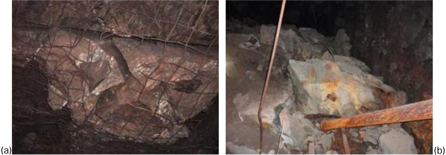
a Mesh that failed as result of corrosion; b fall of ground attributed to corroded rock support
A support system is considered to have failed when it no longer provides the support it was designed for. This can be brought about by failure of any element of the support, such as the rock bolt or mesh. The reduction into support capacity as a result of corrosion is currently not explicitly considered in the selection and design of an underground support system. Quite often, corrosion is recognised as an issue during an investigation in the mechanisms and causes of failure that may have resulted in a fall of ground. Usually, the emphasis is on fracture analysis aiming to identify the contribution of corrosion to a unit or system failure (Hadjigeorgiou et al., 2002). Fracture analysis focuses on the separation of a solid body into two or more parts under the action of stress that initiates and propagates the formation of cracks. A ductile fracture mechanism is characterised by considerable plastic deformation before and during propagation of a crack.
In recognition of the importance of potential degradation of support, efforts have been made to develop classification systems to identify the corrosiveness of mining environments (Robinson and Tyler, 1999; Li and Lindblad, 1999; Villaescusa et al., 2008). Currently, however, no classification systems linking corrosion to ground support are widely accepted or implemented at mine sites. This can be attributed to a variety of reasons, such as site-specific considerations, lack of substantial data to support the assertions of the classification systems and to back their recommendations, and possibly the lack of onsite expertise to implement these systems.
Based on in situ investigations and comprehensive laboratory experiments and testing, mine environments that contribute to the corrosion of support have been scrutinised. After collecting sufficient data for a comprehensive analysis, a framework was developed for the selection of appropriate support strategies for underground hard rock mine conditions susceptible to corrosion. Furthermore, this work provides recommendations that can be used to predict, with some degree of confidence, the operational life of a given support system. This can have important safety and economic repercussions for underground mines.
In situ and laboratory investigations
During the last 5 years, seven underground mines in Canada have participated in a long-term study of the influence of corrosion on support performance. Participating mines were selected to obtain a wide range of different mining environment, geology, ore deposit, and mining methods (Dorion and Hadjigeorgiou, 2008).
The visual corrosion system developed by Hadjigeorgiou et al. (2008) was used to qualify the impact of atmospheric and aqueous conditions on the support. This was complemented by a comprehensive testing programme to monitor aqueous and atmospheric corrosion that involved direct measurements using corrosion coupons and analytical methods. An analysis of water samples is summarised in Table 1. Parameters recorded included acidity or alkalinity, conductivity, solubility, and salinity.
Analysis of water samples collected at several mines
Acidity or alkalinity is measured by a pH value defined as −log(H+). Alkaline environments are characterised by high pH values with acidic solutions having low pH values. Acidic solutions are more corrosive and attack metals. Conductivity, the ability of a solution to transport current, is recorded in siemens per metre (S m−1) in SI units. As the conductivity of a solution increases, in most cases, so does the corrosion of immersed metals. Solubility is the quantity of an ion or gas in a solution. A high oxygen concentration in water results in a high rate of corrosion of iron. The corrosion rate of iron increases in the presence of higher dissolved oxygen. Salinity is reported as total dissolved solids (TDS) and quantified as parts per thousand or parts per million. In general, saline waters have a higher conductivity. The dissolved oxygen readings were calibrated to take into account the atmospheric pressure and water salinity and are reported in parts per million. Water sample temperature was recorded in degree celsius. Typically, corrosion rates increase as temperatures increase.
An appropriate interpretation of the results presented in Table 1 requires attention to the specificity of each mine. For example, mine 4 operates at greater depth and as a result of the geothermal gradient, the ground water at two sampling sites is almost 20°C higher. High temperatures increase the susceptibility of a support system to corrosion. Only mines 4 and 5 were characterised as acidic environments; the rest of the mines were described as weak alkaline or normal environments. The pH values of collected water samples varied from 3⋅4 to 8⋅0, and oxygen solubility ranged from 5⋅9 to 15⋅6 ppm.
The undertaken chemical analysis revealed a high concentration of aggressive ions such as Cl− and SO4−. Mine 1 is an example of mine having high Cl− concentrations ranging from 1938 to 5701 ppm whereas the higher SO4− concentrations are associated with mine 6 (2737–18 053 ppm) and mine 4 (19 029–45 757 ppm). Aggressive ions in a solution attack the thin protective film that forms on the surface of metals, thus making the metal more susceptible to corrosion. The impact of selected ions on the corrosivity of an environment has to be interpreted with reference to the presence, or absence, of inhibitors such as HCO3− and Ca+.
Atmospheric corrosion is the natural degradation of material exposed to air and its pollutants. The rate of atmospheric corrosion is influenced by the relative humidity (the ratio of the quantity of water vapour present in the atmosphere to the saturation quantity at a given temperature). Corrosion rate increases beyond a critical humidity of over 60%. Atmospheric corrosion is further accentuated by the presence of pollutants such as gas and particles. All these conditions are often present in underground mines. Furthermore, the ambient heat in deep mines also has a direct impact on the corrosion resistance of support systems. It is generally accepted that corrosion activity will double for each 10°C raise in temperature.
Table 2 provides a summary of information collected during the mine site visits. Most mine sites were characterised by high relative humidity that contributes to corrosion.
Average atmospheric data at selected sites between July 2008 and January 2009
Furthermore, the authors successfully used corrosion coupons to quantify corrosion rates under different mine conditions following ASTM G4-01 and ASTM G1-03 standards (Fig. 2). Finally, the loss of tensile strength as a function of corrosion rate was determined in the laboratory (Dorion et al., 2009, 2010).
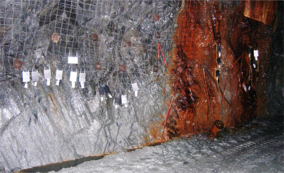
Corrosion coupons attached to the mine screen on the drift wall, exposed to atmospheric and aqueous conditions
Collected corroded rock reinforcement and support elements were brought to the laboratory to determine the capacity of corroded mesh, plate and friction bolts. These were complemented by microphotography to identify the type of corrosion on collected sample (Fig. 3) and X-ray diffraction to determine the most abundant mineral species in the corrosion products. Microscopic observations helped identify the main corrosion forms and provided an insight into the impact of rock and mineral particles on corrosion of the steel support. Scanning electron microscopy (SEM) was used to identify and compare forms of corrosion and corrosion products observed at the collected rock support units (Fig. 4).
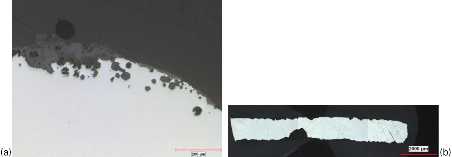
a Microphotography of mesh subject to pitting corrosion; b microphotography of a piece of a corrosion coupon exposed to atmospheric condition with non-uniform and pitting corrosion
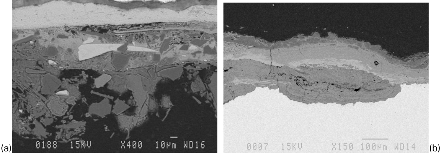
a Scanning electron microscopy (SEM) photography of a plate corrosion crust containing many different minerals particles; b SEM photography of a corrosion coupon exposed to atmospheric corrosion
Interpreting in situ observations and laboratory investigations
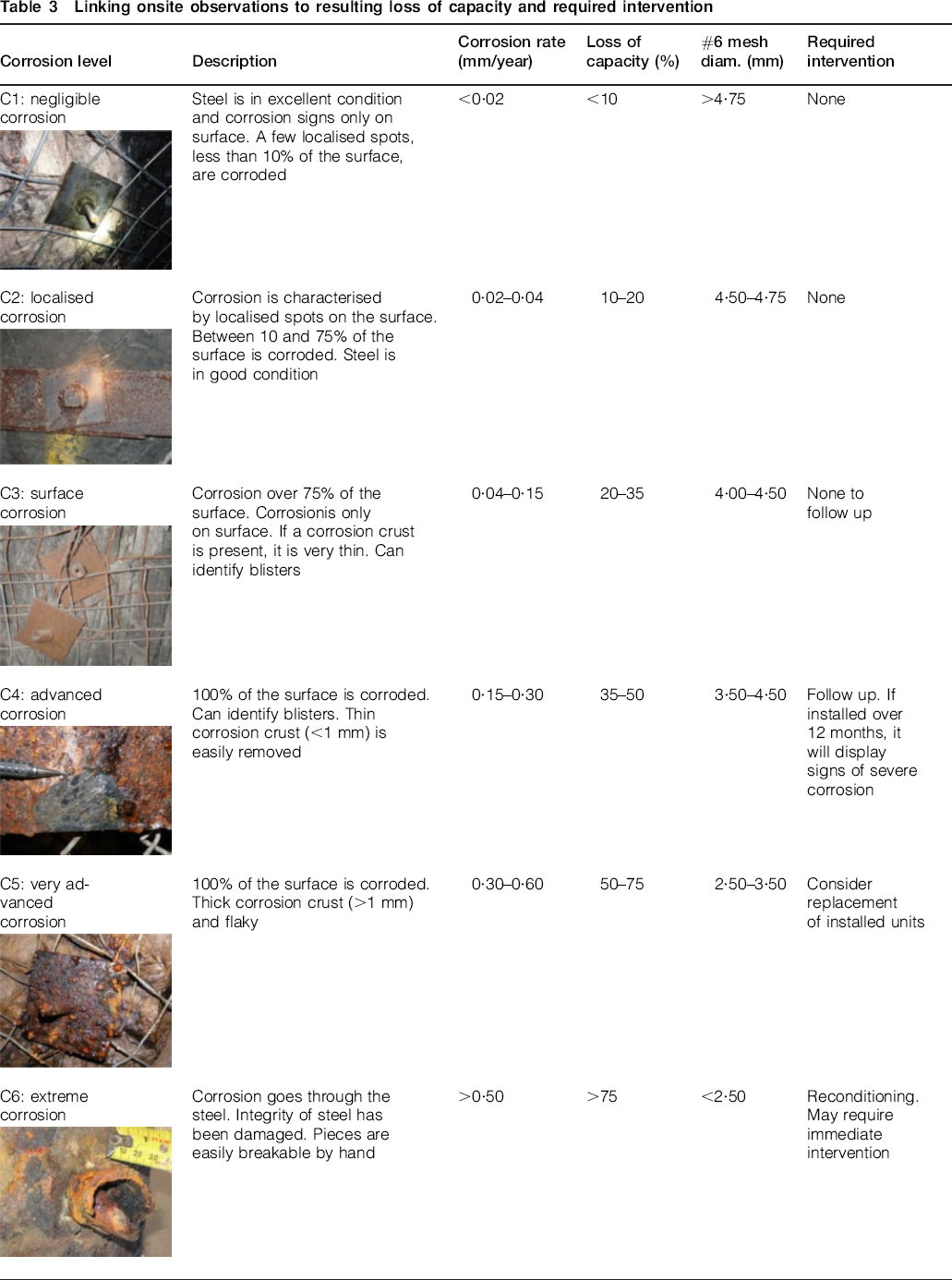
For practical purposes, it is useful to be able to link in situ observations of corrosion on support to estimates of corrosion rates. Table 3 provides a series of recommendations linking onsite observations on the level of corrosion to resulting corrosion rate and loss of capacity. In Table 3, the estimated corrosion rate is based on visual observations of corroded support and is linked to the equivalent corrosion rate reported on coupons installed for a 1 year period. Furthermore, suggestions and recommendations are made on the need for required intervention. This may involve replacing or rehabilitation of corroded reinforcement and support elements.
Linking onsite observations to resulting loss of capacity and required intervention
Although aqueous corrosion is often attributed to low pH, other factors come into play. For example, concentrations of dissolved oxygen in water were seen to contribute to corrosion in underground mines (Hassell et al., 2004). During the present investigation, corrosion coupons were installed under a range of aqueous conditions. It was observed that conductivity was the controlling factor for water with pH between 5 and 8. The influence of iron bacteria is also important as coupons installed for 12 months in water with iron bacteria showed high corrosion rates. Solid mineral deposits on the reinforcement and support steel create a barrier and result in lower corrosion rates over time. The corrosion rate of steel as a function of water conductivity is illustrated in Fig. 5. The applicability of this graph is for water of pH between 6 and 8 and conductivity under 6000 μS.
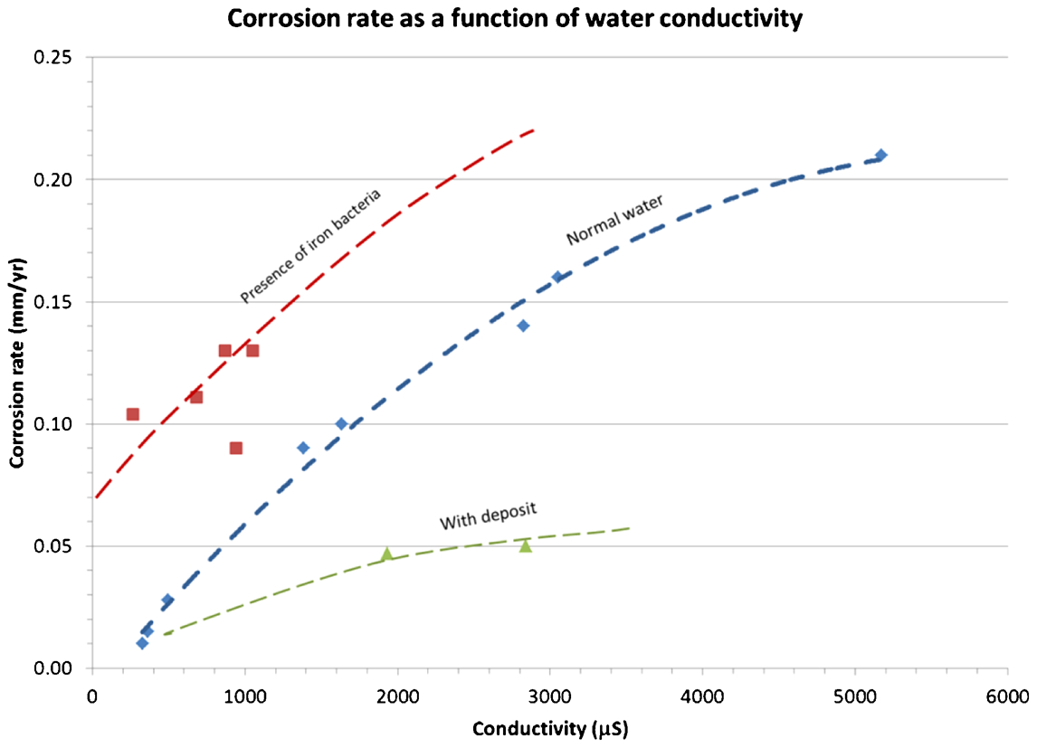
Determining corrosion rate as function of conductivity of the water, pH 6–8
Loss of capacity because of corrosion
Loss of capacity of reinforcement elements
The loss of capacity of bolts exposed to ‘low to moderate corrosion conditions’ and to ‘moderate to high corrosion conditions’ has been demonstrated by pull out tests on Swellex bolts as reported by Charette et al. (2004) and Charette (2012). Villaescusa et al. (2008), simulating conditions in Australian hard rock mines, suggested service life estimates for cable strand in strong groundwater flow environments. In this work, the loss of capacity of friction bolts by extrapolating from work in corrosion chambers, laboratory testing and onsite observations has been addressed.
Loss of capacity of #6 mesh
During this project, more than 60 samples of #6 mesh screen, displaying a range of corrosion levels, were tested in tension (ASTM E8-99). Results were compared with non-corroded samples and results from Villaescusa (2004). Before conducting measurements of the diameter of the strands of wire, the corrosion crust was peeled off using a scraper and steel wool and the minimum diameter of the strands (in millimetres) was measured using a calliper. It was thus possible to determine the residual tensile strength of the wire, or the loss in strength, since installation. The relationship between the break capacity and the diameter of the wire strands, and the correlation between percentage of the residual capacity of wires #6 and their diameter (Fig. 6) were estimated as


Theoretical relationships between capacity of #6 mesh and diameter of wire strand
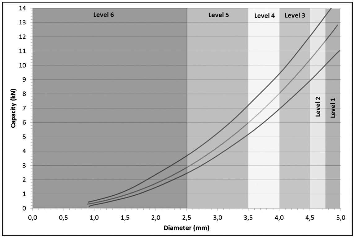
For practical purposes, it is possible to use Figs. 7 and 8 based on design lines obtained using the above relationships for various corrosion levels. In essence, this approach provides a link to onsite observations described in Table 3.
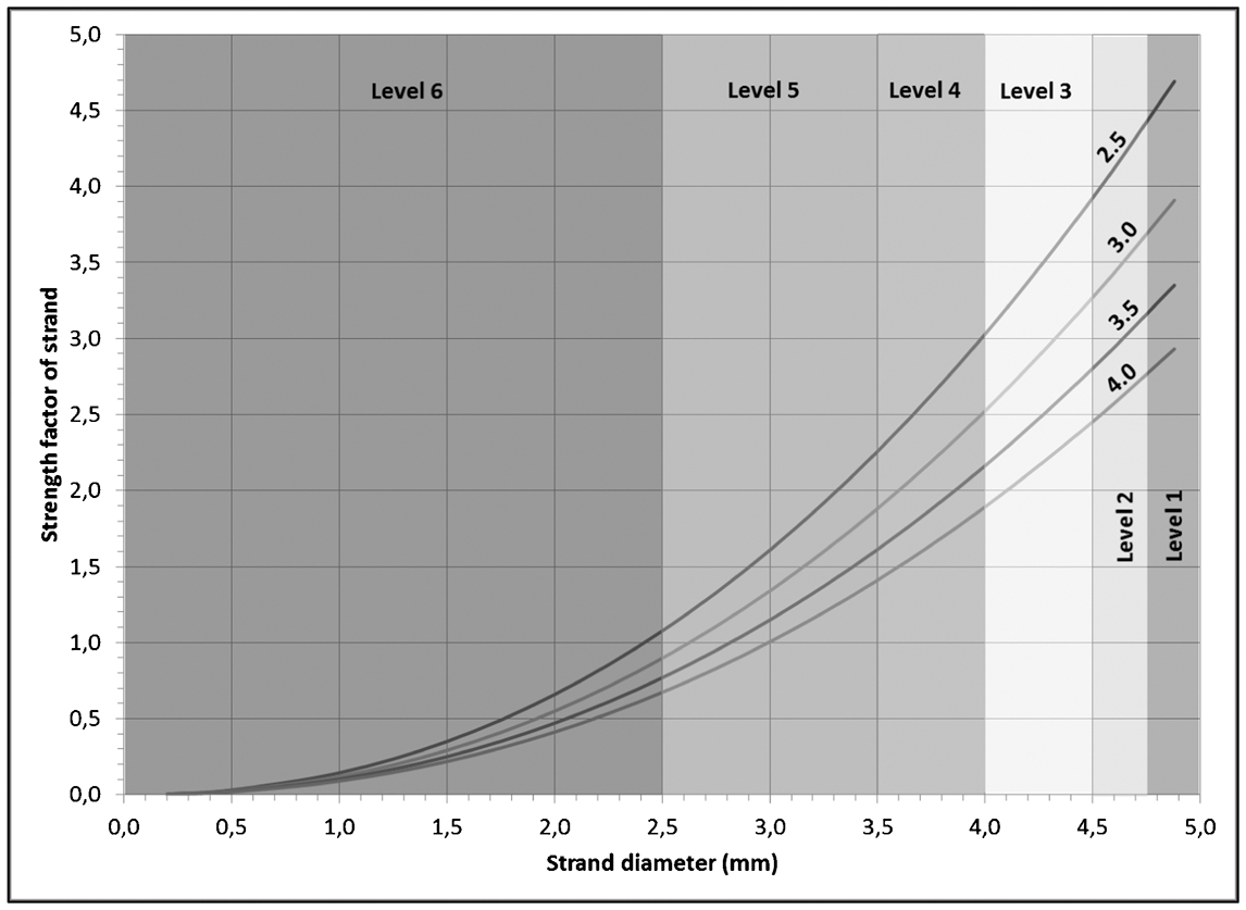
Relationship between residual capacity of strands and their diameter when screen is loaded with a 0⋅1 m3 of rock of given specific density (2⋅5, 3⋅0, 3⋅5, 4⋅0)
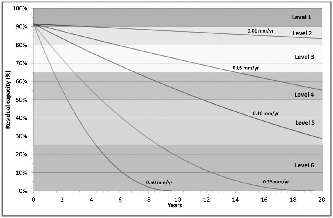
Residual capacity of mesh #6 as function of time for various corrosion rates
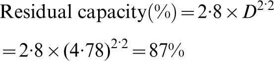
A first approximation of the residual capacity can be estimated, under different corrosion rates, based on the time of exposure, for example, for an initial diameter of #6 mesh of 4⋅88 mm exposed to a corrosion environment that is characterised by a corrosion rate of 0⋅05 mm/year. It is recognised that the load-bearing capacity of mesh should contain small rock blocks that can detach between reinforcement elements. In this context, 0⋅1 m3 of broken rock should be retained by a wire mesh used with a rock bolting patent of 1⋅2×1⋅2 m. The mesh is pinned using short bolts (18–24 inches long, 45⋅72–60⋅96 cm). Based on the design chart in Fig. 7, the loss in mesh capacity after 2 years of exposure (2 years×0⋅05 mm/year) and assuming a constant corrosion environment, the mesh diameter will be reduced to 4⋅78 mm.

Selection and design of support systems accounting for corrosion
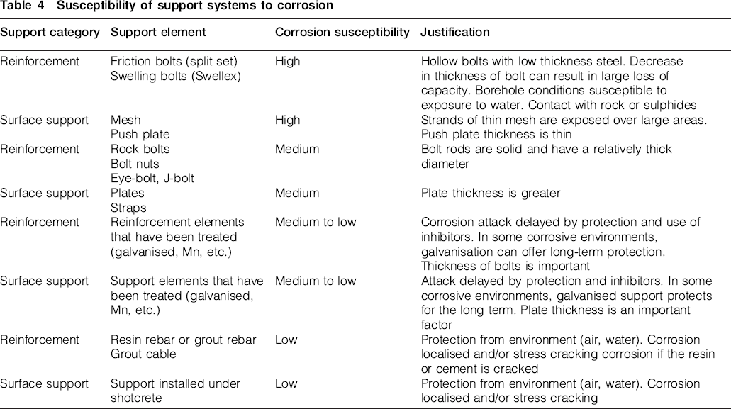
There are several guidelines for the selection and design of support systems. Quite often mine operators rely on experience, or the use of empirical and analytical tools. A common limitation of most approaches is that they do not seem to account for the potential impact of corrosion on the longevity of a reinforcement or support element. Table 4, based on the in situ and laboratory investigations, aims to provide a tool to alert mine operators to the susceptibility of reinforcement and support elements to corrosion. It is recognised that failure of any element can result in failure of the support system.
Susceptibility of support systems to corrosion
The flowcharts in Figs. 9 and 10 provide a pathway to characterise the susceptibility to corrosion of different mining environments, and guide the planning and conduct surveillance (monitoring) of support in place. These charts should be used with classification charts of aqueous and atmospheric corrosion and with respect to support susceptibility guide for assessing corrosion.
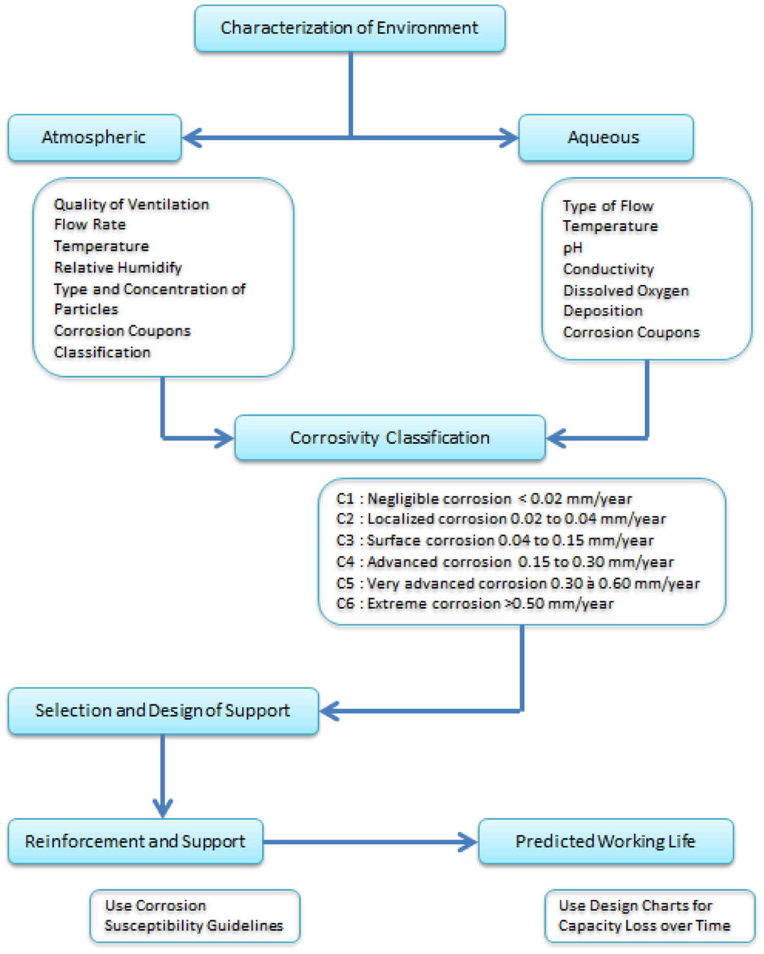
Design methodology for corrosivity classification and selecting of reinforcement and support
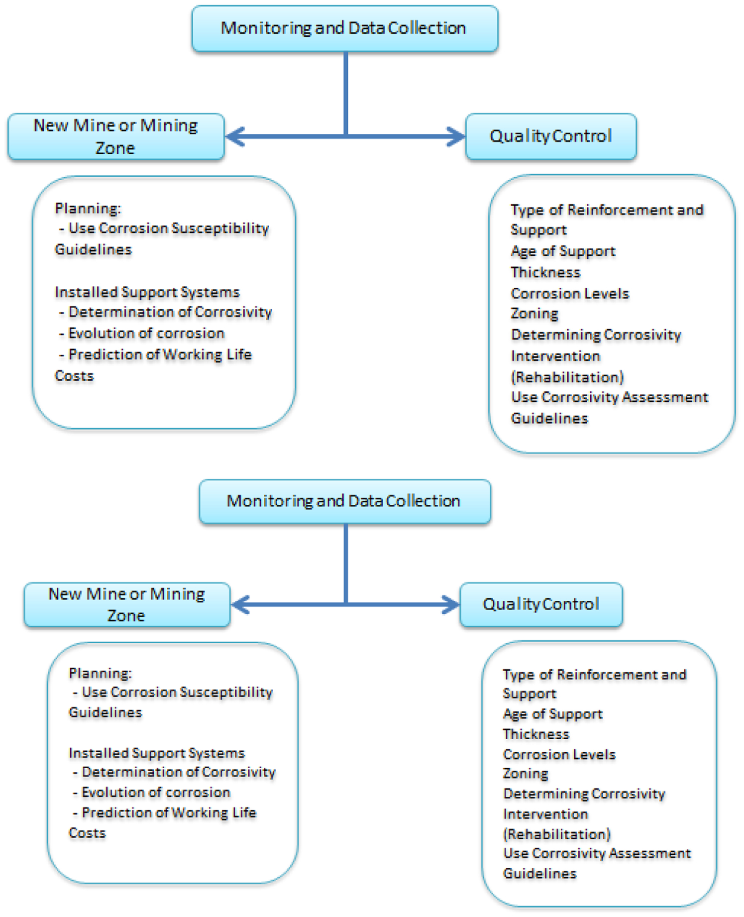
Use of monitoring data for decision making
There are several tools that can be used to characterise the corrosivity of a mining environment exposed to aqueous and atmospheric conditions. As the field studies demonstrated, a number of variables can result in aggressive corrosive environments for rock support systems. The use of the analytical tests in conjunction with the corrosivity classification can provide a design tool and can allow the reporting of corrosion in a consistent matter by those responsible for quality control of rock support systems. It furthermore provides a tool to monitor the evolution of support system corrosion support over time and allow time for prompt intervention as required.
This process does not replace the geomechanical design guidelines for the selection of support systems. Rather it complements the selection and design process as it identifies the implications of using a particular reinforcement or surface support element in a corrosive environment. As such it can be useful in any trade-off study that has to account for geomechanical, corrosion, economic and production considerations in the choice of a support system.
Conclusions
The corrosion of support systems has significant economic and safety consequences for operating mines. A better understanding of the conditions that control the corrosion rate of support systems can be used to predict how long it will take for the support capacity to be reduced based on the mineralogy of an orebody. This in turn can be used by mine operators in mine planning, to improve strategies for choosing support. For instance, different support materials may be used depending upon whether an area is for short- or long-term access. In addition, it can be used to identify areas that may need reconditioning of support.
It has been demonstrated that corrosion coupons provide an excellent method to quantify the corrosion rate of support in an underground mining environment. Coupons installed at different sites provided a consistent narrative on the evolution of corrosion of support in a range of environments. The implementation of a tensile test programme demonstrated the direct relationship between the tensile strength of corroded samples and the recorded corrosion rate, or thickness, of the component. This has allowed the construction of a design chart to quantify the impact of corrosion on the loss of capacity of rock support. A review of onsite observations over a 5-year period and from the experimental programme has allowed the preparation of a series of guidelines on the susceptibility of different support elements. This can provide an additional design tool to identify the optimum support strategy for a given mining operation.
Author Note
This paper has been reproduced with the kind permission of the Australian Centre for Geomechanics, the University of Western Australia. The 7th International Symposium on Ground Support in Mining and Underground Construction Proc. Volume, 13–15 May 2013, Perth, Australia. ISBN 978-0-9806154-7-0, www.acg.uwa.edu.au.
Footnotes
Acknowledgement
The authors acknowledge the continued support of the management and onsite personnel of the following mine sites: LaRonde, Mouska, Doyon-Weswood, Niobec, Persévérance and Géant-Dormant. The authors further acknowledge the technical support provided by Vicky Dodier, Daniel Marcotte, Geneviève Bruneau, Maude Larouche, Jean Frenette and Marie-Josée Bouchard.