
Abstract
The effect of long term exposure of full size bolts to corrosive environments is presented. A special test rig was used to test four bolts under different loading conditions. Four X-grade identical profile bolts, each 21·7 mm core diameter (23·7 mm full diameter) were subjected to prolonged corrosion testing using acid sulphate water. The pH value of the circulated water varied between 3·4 and 4·3. The corrosion exposure test period lasted 3·5 years. Two bolts were axially loaded to 10 t and 20 t force respectively, the third bolt was subjected to a 360 Nm torsion load and the fourth bolt was left unstressed to act as a reference bolt. After the test period ended, the bolts were stripped of their corroded coatings and weighted for weight loss. The diameter of each bolt was subsequently measured, and the loaded bolt samples were first tested non-destructively for tensile cracks and then tested for tensile failure. No cracks were found on post-corrosion bolts tested non-destructively. The failure strength reduction on all four post-corroded bolts was significant, varying between 21 and 39%. The onset of corrosion was not confined to the water targeted mid-section length of the bolt, however, the most severe corrosion occurred at the anchored ends of the bolts, possibly attributed to the combination of several types of corrosion which may have been also compounded with increased surface area of the threading at the bolt ends and excessive aeration corrosion due to increase in air movement.
Introduction
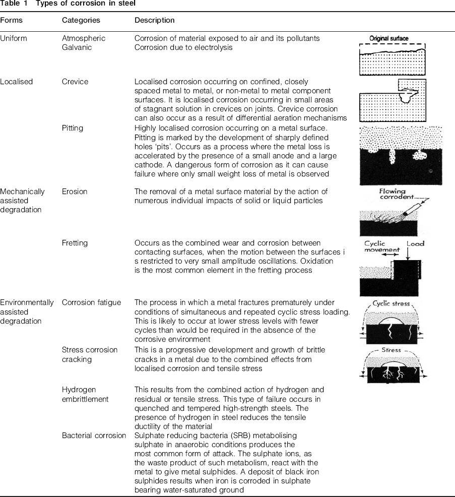
Corrosion is a physical alteration of a material from electrochemical reaction with its environment that often results in reduction of the mechanical properties of that material. Roof bolts are particularly susceptible to corrosion as they can be exposed in their working environment to ground water. Corrosion increases markedly in sulphide ore bodies due to acid runoff. Table 1 shows different types of corrosion that a rock bolt is likely to undergo when used for ground reinforcement. Of all the types of corrosion, pitting is particularly dangerous as it removes material and subsequent capacity for the bolt to deform with strata movements. Sudden failure of a bolt is likely to occur when pitting corrosion is experienced. The type of corrosion depends on the nature of the ground condition and bolt encapsulation. Generally, the type of corrosion and severity of the corrosion can vary along the bolt.
Types of corrosion in steel
Historically the subject of steel corrosion has been of interest to civil and construction engineering. In mining, the interest in the topic is relatively new and follows the introduction of bolting for ground support in mines and tunnelling. According to Baxter (1996) the early corrosion studies on rock bolting were carried out by Swedish and Finish researchers. Various publications include: Tuutti, 1982; Sundholm, 1995; Helfrich, 1990; Moving, 1994; Sundholm and Forsen, 1995; Satola and Aromaa, 2005. In the Australian context, the interest in bolt corrosion began in earnest in the late 1990s and the paper by Gray (1998) in which an emphasis was given to stress corrosion cracking (SCC). An ACARP project was initiated in 1999 to address the observed phenomenon of premature failure of rock bolts in a number of Australian coal mines, with a particular focus on the problem of SCC in rock bolts (Hebblewhite et al., 2002, 2003a, 2003b). Other Australian publications on corrosion include Gamboa and Atrens (2003), Hassell et al. (2005), and Vandermaat et al. (2012). The latter developed an apparatus to study SCC in full sized bolt specimens.
The rate of steel bolt corrosion is influenced by ground water composition, flowrates, water pH, temperature, CO2 content, surface condition, presence of corrosion inhibitors, applied stresses, residual stresses (from workings, forming or welding operations) and any hydrogen sulphide concentrations (Henthorne, 1971–1972; Spearing et al., 2010). Accordingly, a specialised test rig was constructed at the University of Wollongong to study the effect of long term exposure on full size bolts, which are of current use in Australian mines. The study was undertaken in an environmentally controlled laboratory under different bolt loading conditions.
Experimental procedure
The laboratory experiment involved four X-grade rock bolts (0·75 mm profile height and 12·5 mm profile pitch) subjected to similar environmental conditions to examine the effect of corrosion in different test conditions. The testing period lasted 3·5 years. All bolts were secured from a single supplier, and were not tested for steel chemical composition when received.
During testing, all bolts were subjected to a corrosive environment using acid sulphate soil water with corrosive characteristics significantly stronger than that normally found in most mine environments. Stronger corrosive environment was necessary in order to speed up the corrosion process. The method adopted to study corrosion under various bolt loading conditions was as follows:
bolt axially loaded to 10 t force,
bolt axially loaded to 20 t force,
bolt subjected to torsion of 350 Nm, which is almost twice the torsion load applied to the bolt during installation and encapsulation, and
bolt section without loading as a reference bolt.
Factors such as pH, temperature, conductivity and salinity of the corrosive medium were monitored and recorded from the start of the experimental period. Water was sourced from acidic ground water drainage channels that flow into the Shoalhaven River in the South Coast of NSW, Australia. The acidity of the water was thus attributed to the regional acid sulphate soils (Glamore, 2003).
Test equipment
The corrosion testing apparatus consisted of a header tank, which fed water to all test bolts as shown schematically in Fig. 1. Figure 2 shows the laboratory experimental test rig. The dispersion of water on each tested bolt used 13 drippers spaced at 40 mm along a 720 mm long 100 mm diameter PVC manifold tubing, giving each bolt a wetting exposure length of between 520 and 540 mm. Water was supplied from the main reservoir tank, placed about 500 mm above the PVC water manifold tubes. The length of each parallel flanged channel (PFC) loading frame was 770 mm; hence not the full length of the bolt section, confined between the walls of bolt tensioning rig length, was directly exposed to dripper water. The dripped water was collected in plastic trays, placed beneath each tested bolt loading frame and returned to the header tank for recirculation. The rate of water supply to each bolt via drippers was kept consistent and the drippers and hoses, connecting the reservoir tank to the dripper manifolds, were prevented from clogging by being regularly cleaned.
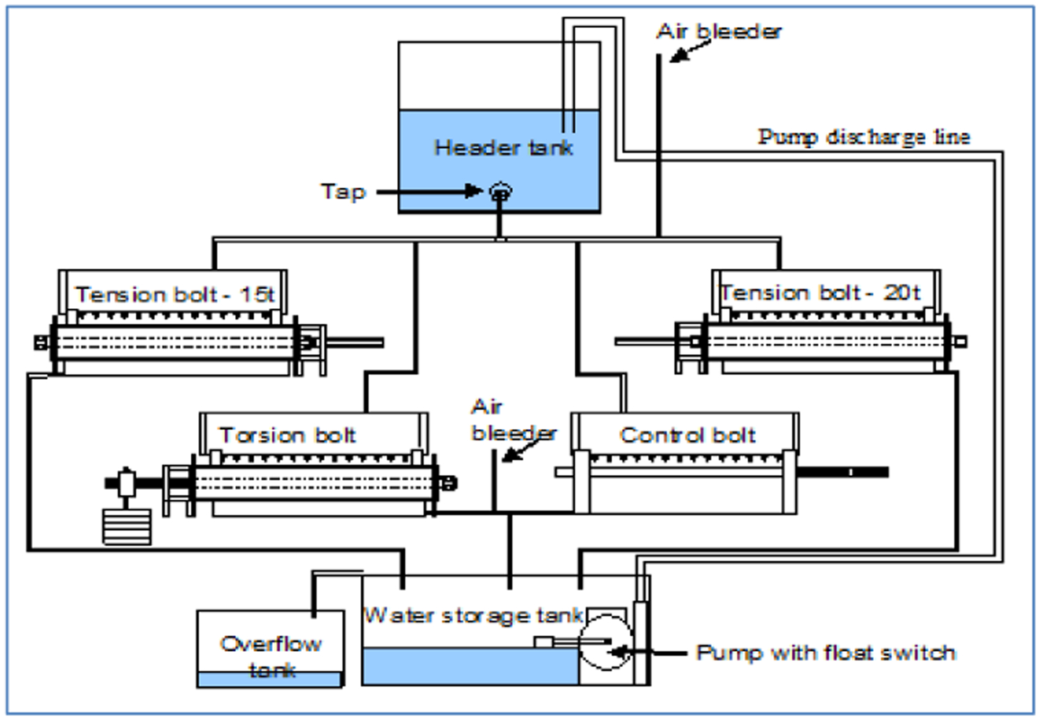
The general layout of the bolt
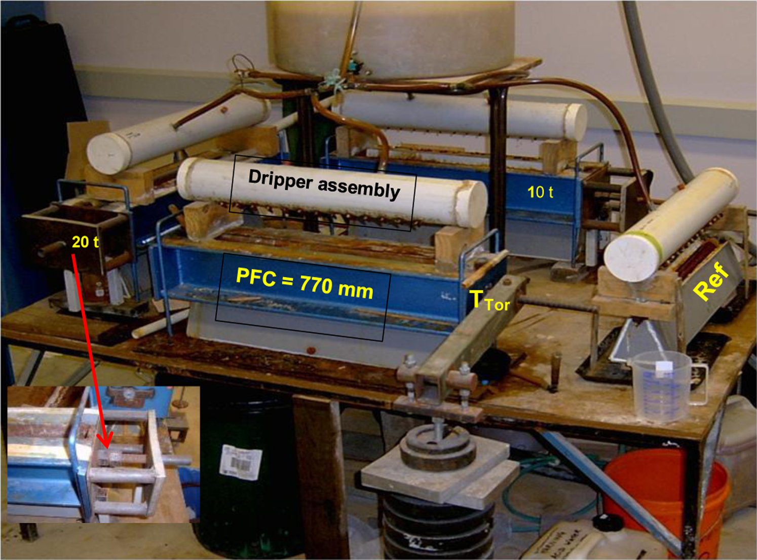
Corrosion testing rig including the dripper assembly and bolt loading frame
Bolt tensioning
Bolt tensioning was carried out using three strong PFC steel frames, which allowed axial loading of two bolts to the predetermined loads of 10 t and 20 t, and torsion of the third bolt. The 9·5 mm thick steel tensioning PFC frames consisted of two 150×75 mm sections. Two 150 mm square, 10 mm thick steel plates weld the two PFC steel channels together and were painted to protect and prevent them from influencing the bolt corrosion. The inner sides of the PFC facing the bolt were covered with a layer of plastic as additional protection against corrosion. The end-plates were drilled with 25 mm diameter holes to allow the bolts to pass through and sit between the beams spaced at 50 mm. The strength of the end-plates allowed the applied tension to be held by an interlocking nut against the sides of the frames as shown in Fig. 3. The PFC section frames were designed to allow the water, which dripped on to the bolts, to be collected in plastic trays placed underneath bolt mounted rigs. The reference bolt (non-tensioned) rested on top of the plastic drip tray, and the dripper tube was supported on a small plastic stand, just above the bolt. The procedure adopted for axially tensioning the bolt is shown in Fig. 3.
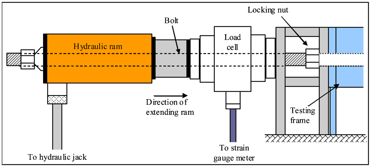
Axial tensioning of bolts installed in the tension rig
Test water
Water was sourced from the Shoalhaven River (NSW, Australia) (Glamore, 2003). The Shoalhaven groundwater was acidic, with variable low pH values ranging between 3·4 and 4·3 measured from water samples taken from the laboratory test circulation tank. The variation in the quality of the water collected from the field was seasonal and at times the water was collected from two separate locations within a two square kilometre area. Owing to the weathering of pyrites forming acid sulphate soil in this area, the water quality was of sulphuric acid concentration. The flowrate of dripping water to each bolt surface was kept between 3 and 3·5 L h−1. Water in the circulation was regularly topped-up with fresh supplies, because of losses from spillage and evaporation.
Reliance on the Shoalhaven River water rather than collecting water from a mine was the preferred option as access to mines to collect water was at times, inconvenient. There was no difficulty in carting water on regular basis from Shoalhaven River as there was an onsite research programme under way by the University of Wollongong, and notably by Glamore (2003).
Recycling of the water through the rig system was achieved using a small submersible pump with a float switch. Constant monitoring of the water condition was recorded as well as a titration analysis of water samples at different times, spanning over 3·5 years of the experimental study. Table 2 shows typical chemical analysis of the experimental test solution used for corrosion experimentation. The chemical analysis of the test solutions for June 2002 and May 2005 were taken from the water storage tank of the bolt corrosion rig shown in Fig. 1. No corrosion tests were undertaken using real mine water. Figure 4 shows the graph of both pH level and circulating water temperature variations with time for the later years (February and November 2005) of the study period.
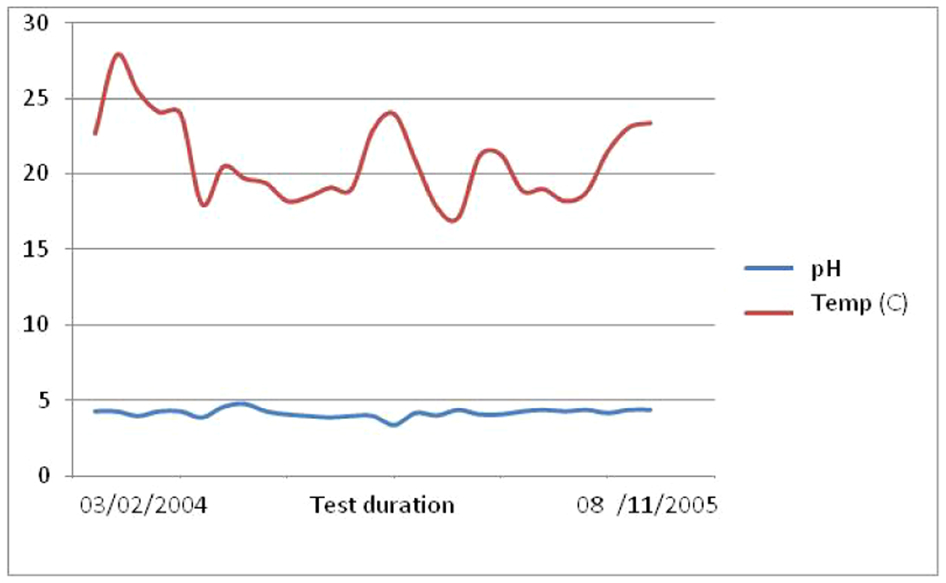
Laboratory room temperature fluctuation and water pH values between February 2004 and November 2005
Chemical analysis of test samples 1–2 collected from the Shoalhaven River with the third sample from a mine, being used for comparison purposes
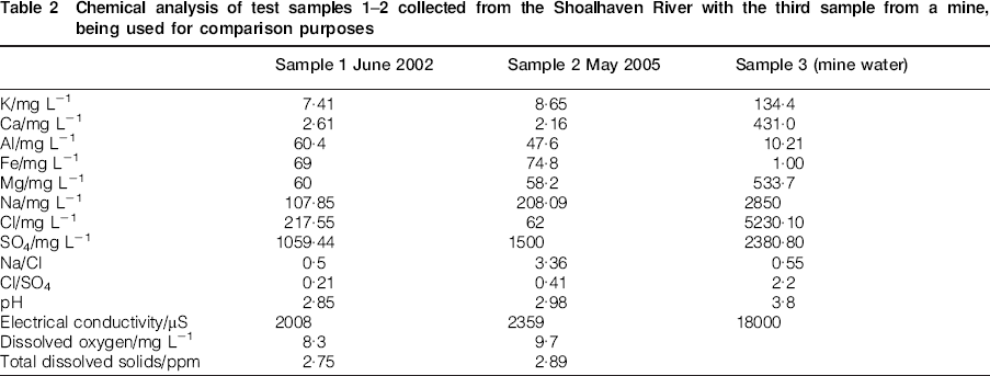
Table 2 shows the analysis of the water quality from the Shoalhaven River and water quality of mine water collected from one mine in the southern coal field of Sydney Basin. It is clear from Table 2 and graphs in Fig. 4 that the test water from the Shoalhaven River was an aggressive solution that was suited to corrosion reactions in comparison from a typical mine water sample shown in Table 2. It must be stressed that no corrosion experiments were made using mine water and the water chemicals shown in column three of Table 2 is provided for comparison reasons only. High concentrations of chloride ions as well as low pH level suggest that the solution was acidic. The large proportions of sulphates reinforced the weathering of the pyrite from the water origin, which assisted in decreasing any resistance to corrosion such as the formation of oxide layers. The sample solutions also show that the water had low dissolved oxygen content, which is not favoured in corrosive reactions; however this was not thought to hinder corrosion in this test as oxygen was available to the metal surface from the atmosphere and the solution had low pH and hence was not necessarily dependent on oxygen. It must be stressed that the solutions used throughout the experiment was the same throughout the test period and the top-up water was available from the reserve tanks.
Test bolts
Four M24 (22·0 mm core diameter) X-grade (AX) four bolts selected for this investigation were of the common bolt size used in Australian underground coal mines. In particular, the selected low profiled bolts with 12·5 mm profile pitch have wider usage than other types of the same size, and its share of application is around 70%.
Generally, the chemical analysis conducted on the bolts and shown in Table 3 indicates a high carbon manganese steel. The chemical analysis of bolts was undertaken post-corrosion tests, and no chemical tests were made before the commencement of the tests. It had been expected that all the bolts would have the same chemical composition as they were sourced from the same supplier. The post test samples were stripped of the corroded deposit layer to bare metal surface and the diameters measured. The average reduction in diameter of each corroded bolt is shown in Table 4. The reduction in each tested bolt diameter was determined by the averaged multiple diameter measurements of 30 readings along the wetted lengths of each bolt (along the 520 mm middle section of bolts). Both core and full diameter reduction due to corrosion were carefully measured, and on occasions, excessive corrosion of the profiles presented difficulties in separating the core diameter from the full diameter measurements of the bolts.
Chemical analysis of the test bolts (source: Bureau Veritas Australia, 2012)
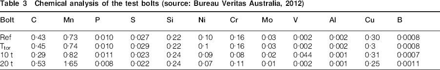
Ref: reference bolt; Ttor: Torsion bolt; 10 t: 10 t tensioned bolt; 20 t: 20 t tensioned bolt.
Yield and ultimate strength failure load of the tested bolts
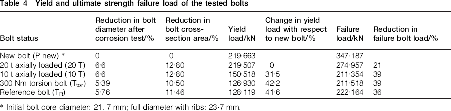
Initial bolt core diameter: 21. 7 mm; full diameter with ribs: 23·7 mm.
Results and discussion
Figure 5 shows pictures of various sections of pre and post-tested bolts. It is clear that there were some variations in the post-testing diameters along the length of each bolt. In general, the loss in bolt core diameter along the targeted sections of all bolts ranged between 5·39 and 6·6%, which translates to loss in core cross-sectional area between 10·50 and 12·80%, with the minimum loss being the reference bolt as shown in Table 4.
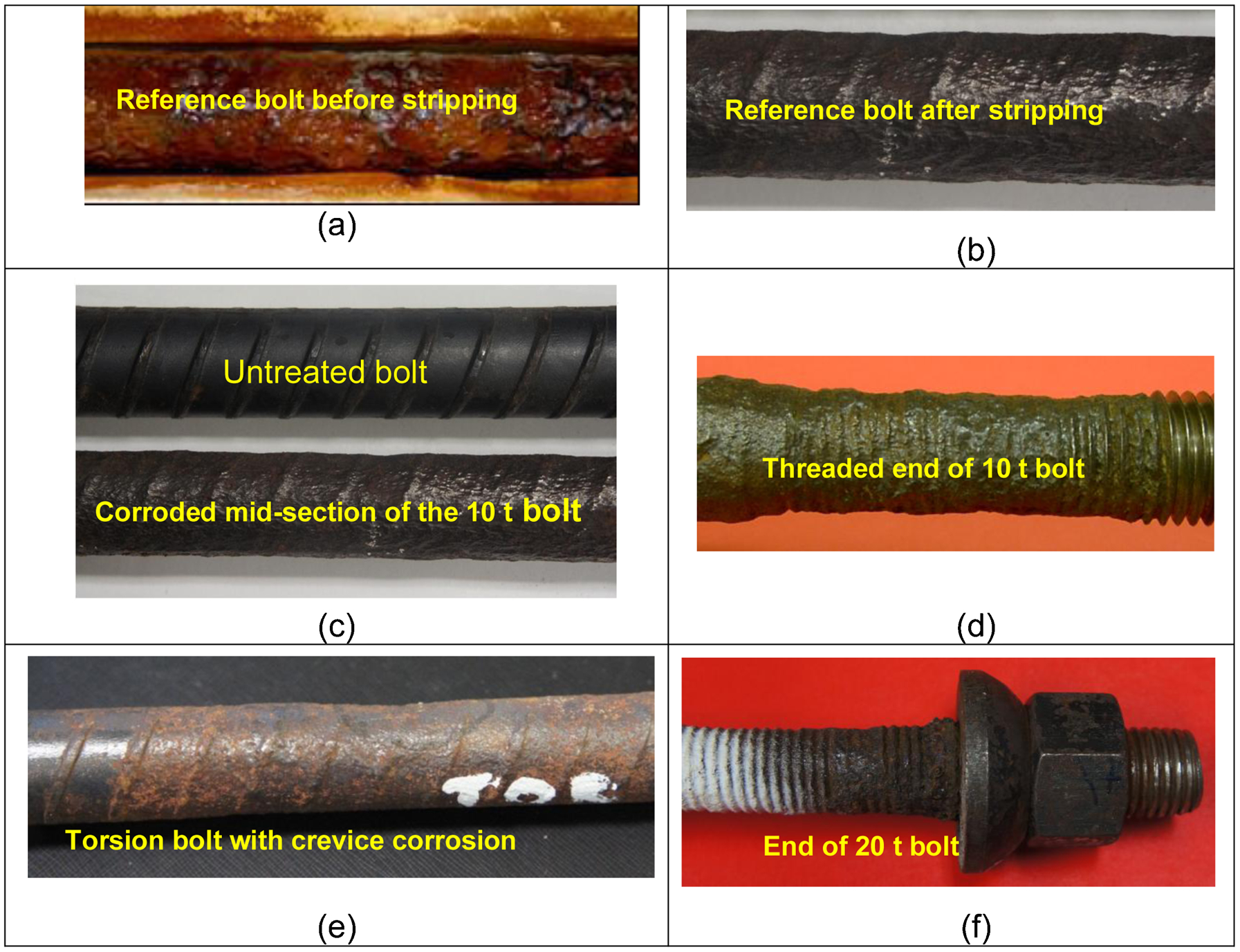
Photos of parts of various corroded bolt sections compared with un-corroded section. Section e shows the evidence of crevice corrosion due to aeration at bolt end
Noticeable and excessive corrosion occurred on the threaded bolt-ends section and at the sections of the bolts passing through the steel PFC end plate holes. These two sections were outside the direct water dripping zones (targeted zones) and accordingly the reduction in diameter was not measured.
The end threaded end parts of the bolt with maximum corrosion were for the purpose of bolt tensioning on the PFC loading frame sides. Figure 5d–f show corroded bolt surfaces located in the vicinity of the PFC bolt tightening hole. This type of crevice corrosion is most likely to be the result of differential aeration.
The average reduction in borehole diameter of all four bolts due to 3·5 years of corrosion testing was in the order of 11·7%. This is equivalent to a cross-sectional area reduction of around 10·7%. This level of cross-sectional area reduction was significantly less than the percentage reduction of the bolt tensile strength. The failure loads of reference, torsion and 10 t loaded bolts are reasonably close as indicated in Table 4, and only the 20 t loaded bolt has a higher failure load, the possible reason may be due to the chemical composition of the bolt as is explained later in this section
The accuracy and reliability of the corroded bolt diameter measurement were affected by the level of bolt surface irregularity due to the bolt surface pitting as well as near total erosion or corrosion of bolt profiles around the bolt. This made it difficult to differentiate between core and full diameter bolt cross-section measurements. The weight loss measurement, before and after the test, could not be related solely to the designated wetted section (targeted section) of the bolt.
Two forms of corrosion were identified in this experimental study, pitting and crevice corrosion. Pitting corrosion was evident in the mid-sections of the bolt directly along the dripping zone as seen in Fig. 5a–c. Crevice corrosion on the other hand occurred at the bolt ends as demonstrated in Fig. 5d–f. The mounting of the torsion bolt on the PFC tension frame also generated crevice corrosion as one side of the bolt required no direct axial loading tightening and the end-plate holes of the PFC was unobstructed, contributing to an increased flowrate and humidity over the bolt surface. The crevice corrosion is shown in Fig. 5e. Normally crevice corrosion occurs in the confined space as a result of a differential aeration mechanism. Also, the excessively crevice corroded zone shown in Fig. 5e was not in direct contact with the dripper waters as the last drip nozzle was some 60–70 mm away from either side of the rig side holes housing the bolt ends. This sort of corrosion is most likely to be observed underground at the collar on an installed bolt in a hole with less than complete encapsulation, thus leading to the onset of SCC, particularly when the protruding bolt end is subjected to external shear loading or impact. According to Gray (2006) this kind of corrosion was often found in field observations particularly at Angus Place Mine, NSW, with severe corrosion taking place along the free length of the bolt, even though there was no apparent free water. A damp corrosive atmosphere is sufficient to cause corrosion and perhaps this is because of the greater presence of free oxygen in air rather than under water. Also, the excessive surface area of the threaded section of the bolt also has an influence.
A non-destructive test was carried out on the 20 t loaded bolt to determine whether there was an onset of SCC of the sample after it was subjected to the 20 t tension force. Using magnetic particle inspection, repeated tests on the sample produced negative results which indicated no cracks were found.
Figure 6 shows the load–displacement graphs of various corrosion tested bolts as well as an additional new bolt, which was not subjected to the corrosion test. Table 4 shows the various bolts load–displacement values at yield as well as the ultimate strength values as seen in column six.
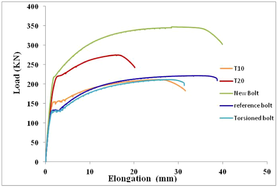
Load–displacement profiles of various bolts
One of the noticeable profiles of the load–displacement graph was that the strength value of the 20 t tensioned bolt (20 T), was relatively greater than the other three bolts in the test. The peak load of 20 t loaded bolt was in the order of 274 kN (27·94 t). This level represented a reduction of around 21% in strength with respect to the failure strength of a similar new bolt with its tensile strength failure load of 347 kN (35·38 t). The 10 t (10 T) tensioned bolt achieved 39% reduction in strength and the reduction in strength of the torsion bolt (Pt) was 39% and the reference bolt (Tr) was 36%. The unusually lower percentage reduction in the failure load of the 20 t bolt as compared to other corroded bolts is likely to be attributed to the steel composition of the bolt as shown in Table 3. It is clear that the carbon and manganese content of the 20 T bolt was greater than with the other three bolts.
Further examination of the manufacturing source of all the tested bolts, based on testing of 100 mm long targeted section of each bolt revealed the following:
Bolt sample 10 t had been manufactured from medium plain carbon steel consistent with a designation of AISI1030, while bolt samples Ref and Ttor had been manufactured from medium plain carbon steel, consistent with a designation of AISI1045. Sample 20 t had been manufactured from a high plain carbon steel consistent with a designation of AISI1355. According to Sullivan (2012), the variation in steel compositions of the bolts was due to bolts coming from different plants of manufacture, which was not known to the researchers at the commencement of the study.
Boron was detected at levels >0·0005%, however none of the samples contained the shielding elements Al, Ti, Nb or Zr, usually accompanying an intentional boron addition.
Table 5 shows Vickers hardness tests performed on the transverse section taken from each sample at the mid radial positions, and the results presented along with the approximate equivalent tensile strength. It is clear from the hardness tests that 20 T bolt has significantly higher tensile strength which is in agreement with the strength test results shown in Fig. 6.
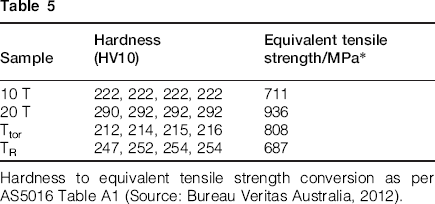
Hardness to equivalent tensile strength conversion as per AS5016 Table A1 (Source: Bureau Veritas Australia, 2012).
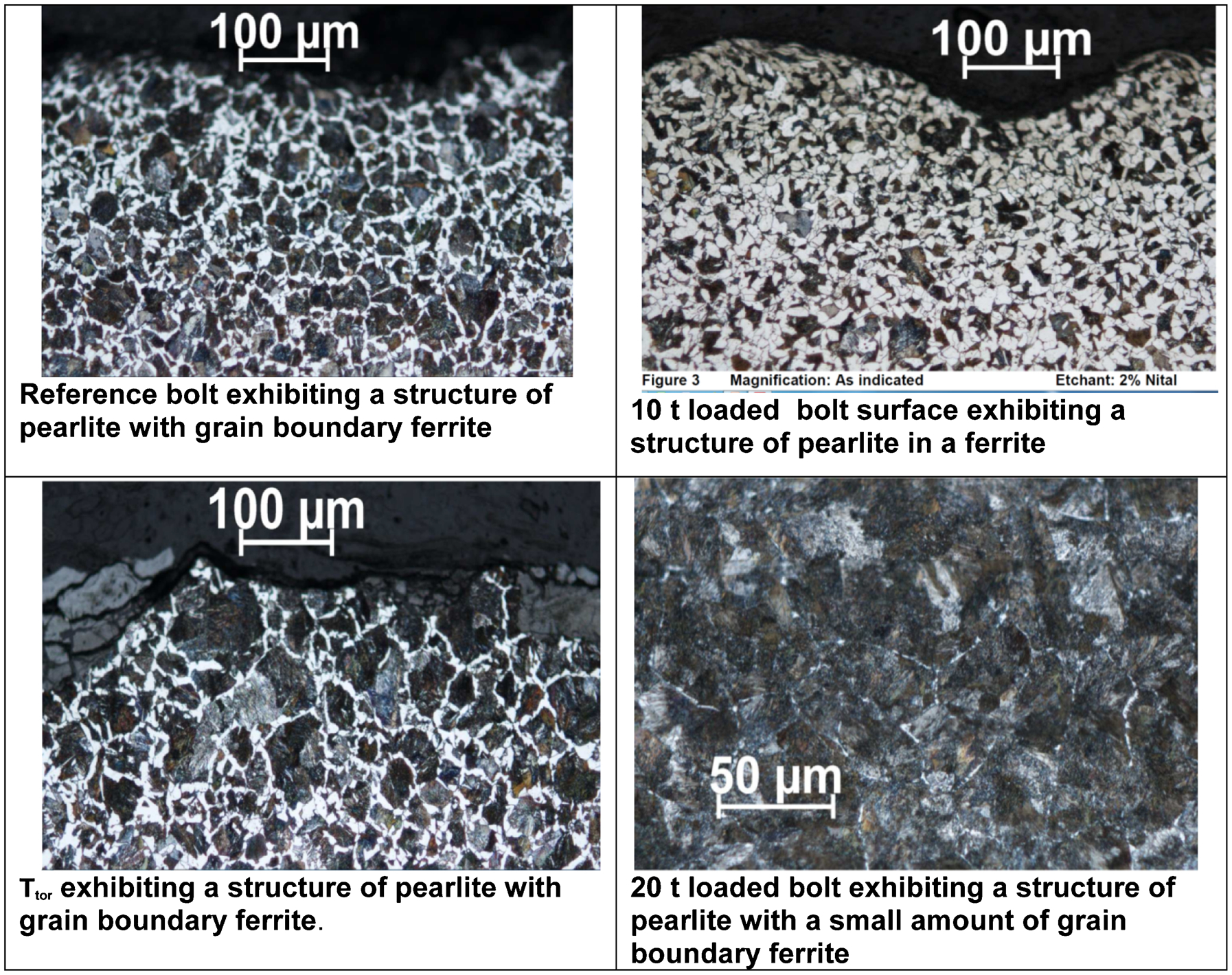
Figure 7 shows the photos of transverse sections taken from four bolts shown after polishing and micro etching using 2% nital etchant. All four samples revealed a uniform etch pattern, with sample 20 T etching darker consistent with the higher carbon content. Further analysis of the bolt samples structures showed variations in the steel structures as depicted in Fig. 8. The reference bolt exhibited a pearlitic structure with grain boundary ferrite. The 10 t loaded bolt surface exhibited structure of pearlite in a ferrite. The Ttor bolt had a structure of pearlite with grain boundary ferrite, and 20 t loaded bolt exhibiting a structure of pearlite with a small amount of grain boundary ferrite. The 20 t loaded bolt structure had relatively higher carbon and manganese content in comparison with the other three tested bolts. Accordingly, it is important that the bolt manufactures/suppliers make available the material composition of the bolts when these are to be used in adverse ground conditions, and only high manganese steel bolts should be used where corrosive water is likely to be present. The practical implication of the study clearly demonstrates that, where bolts are used in corrosive environment, they must be fully encapsulated and appropriately sealed to reduce the early onset of corrosion, particularly the exposed, protruding end of the bolt with increased surface area of threading, which is vulnerable to early corrosion.
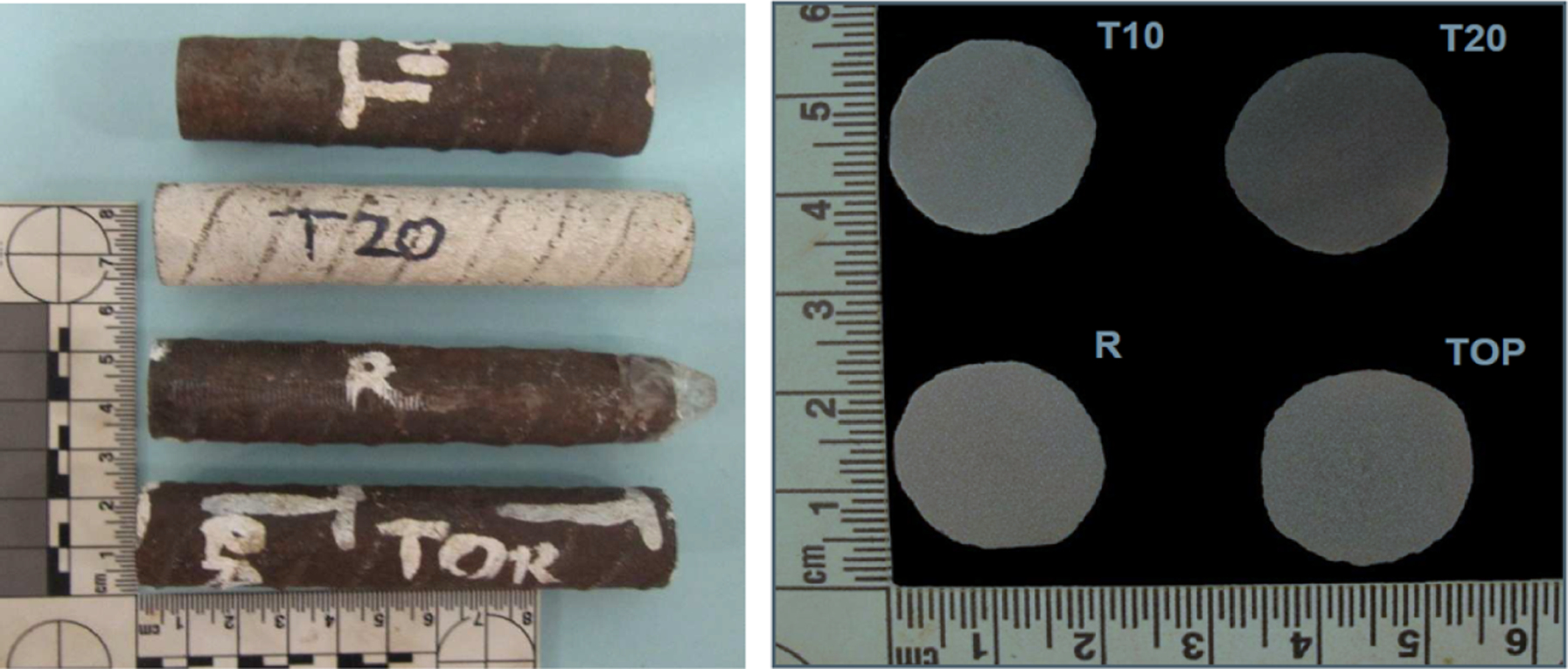
Etched transverse section of all four bolts with 2% nital etchant
Variations in bolt steel structures
Future corrosion studies should consider testing bolts in different loading levels, bending and shear conditions.
Conclusions
A prolonged experimental study using high carbon manganese X-grade rock bolt showed that significant corrosion has occurred in an aggressive low pH groundwater. Both pitting and crevice corrosion was identified as the type of corrosion that is most likely to occur along the tested bolt length. Using low pH water to speed up the corrosion process was considered as an acceptable and viable method of conducting bolt corrosion testing in the laboratory environment.
Consistency of the water flow via drippers represents one of the challenging aspects of this long period of the experimental work, hence regular maintenance of the drippers and conduits are essential for the success of this kind of study.
The ultimate tensile strength of bolts subjected to prolonged corrosion tests was reduced by between 21%, for the 20 t bolt, and 39% for the reference bolt, compared with the ultimate tensile strength of a new similar type bolt. Both 10 t and torsion bolts had near equal ultimate tensile strength reduction of 31%. The abnormally high load displacement profile of the 20 t bolt was attributed to different composition steel with high carbon and manganese content in comparison to the other three tested bolts.
The average reduction in borehole diameter of all four bolts over the period of 3·5 years of corrosion testing was in the order of about 11·7%. This level of diameter reduction was significantly less than the percentage reduction of the bolt tensile strength of between 21 and 39%.
Bolts installed in corrosive environment ought to be fully encapsulated or sealed appropriately, to prevent early corrosion due to the increased surface area of the threaded section.
Future corrosion studies should consider testing bolts at different loading, bending and shear conditions.
Footnotes
Acknowledgement
The authors would like to thank Alan Grant, Ian Laird and Robert Rowlan from the school of Civil, Mining and Environmental Engineering, Faculty of Engineering, University of Wollongong for their assistance in the fabrication, maintenance, monitoring and supply of the field water during the 4 years of the experimental study programme. Special thanks to DSI Australia for supplying bolts for this particular study. Constructive comments and suggestions from Meitek Rataj of Sandvik and Glenn Sullivan of Moly-Cop are very much appreciated.