
Abstract
Cost reduction via optimising the scheduling of waste rock placement has a very high potential of success, as large volumes of waste rock are involved in operating an open pit mine, along with high rehabilitation costs. Such scheduling must satisfy both mine planning and environmental considerations, for which mixed integer programming (MIP) models are a well suited methodology. A base MIP model, along with two variants, is created and implemented for a hypothetical mine site. Upon solving the MIP problem with more than two million possible combinations, optimised waste rock placement schedules are automatically generated. The detailed schedules will assist mine planning engineers in mine design and in improving the environmental performance of a waste rock dump.
Keywords
Introduction
Cost reduction is a continuing focus of the mining industry, driven by the world's economy. Material handling costs are among the largest cost components, reported to be worth more than 50% of the total operating cost of a typical open pit mine (Lizotte and Bonates, 1987; Alarie and Gamache, 2002). A large proportion of the total material handling cost is for hauling waste rock to a dump, increasing with increasing stripping ratio and increasing separation between the pit and the location in the dump. Ore is usually hauled to a fixed run-of-mine (ROM) stockpile, which, in most cases, has a constant processing rate, so the haulage cost after exiting the pit remains almost constant. In contrast, waste rock is hauled to a dump of increasing size and height, resulting in an incremental increase in the haulage cost.
The usual method of minimising the haulage cost of waste rock is to minimise the haulage distance and height, and to maximise the productivity of haul trucks in order to reduce the unit cost per unit volume or mass of waste rock handled. Maximising productivity can be achieved by increasing haul truck capacity, improving equipment reliability, providing better operating conditions, and implementing a dispatch system (Lizotte and Bonates, 1987). It is noticed that little study has been devoted to exploring the minimisation of the actual cost components, mainly because of the lack of interest in waste rock, which is seen as a cost of no value, and the complexity involved in the mine planning process. Current mine planning practice is oriented towards ore recovery, with the scheduling of waste rock placement receiving very little attention. A general rule of thumb is to match the capacity of a waste rock dump with the volume to be mined from a pit, and assign the shortest haul to minimise the haulage cost. However, short-term cost control may not necessarily be the best solution in the long term, because of the ever-increasing size of the dump and the need for its eventual rehabilitation. This opinion has been demonstrated by Sommerville and Heyes (2009) in a realistic case study, which indicates that waste rock handling costs could be minimised by carefully planning the placement of the waste rock considering the entire mine life during the planning process.
Apart from haulage costs, there are important environmental issues associated with waste rock dumps. The potential for acid and metalliferous drainage (AMD) from potentially acid forming (PAF) waste rock in surface dumps is a challenging problem faced by many mining companies. Extensive studies (Gazea et al., 1996; Harries, 1997; Kuyucak, 2002; Johnson and Hallberg, 2005) have demonstrated that AMD is a long-lasting problem, threating the natural environment. Johnson and Hallberg (2005) stated that rather than remediation, AMD prevention is the preferred approach.
Williams et al. (2006) described the method of encapsulating PAF waste rock, as illustrated schematically in Fig. 1, in which the PAF waste rock is surrounded by non-acid forming (NAF) waste rock and capped to minimise contact by air and water, which reduces the potential for AMD. However, the volume and type of waste rock mined is dependent on the ore production. Further, the proportion of NAF waste rock typically reduces as mining progresses below the groundwater table. Therefore, it is highly possible that there will be insufficient NAF waste rock available to fully encapsulate the dominant PAF waste rock produced during the later stages of mining. The solution is to stockpile NAF waste rock during the scheduling of waste rock placement, and to plan the future re-handling of this material for encapsulation purposes.
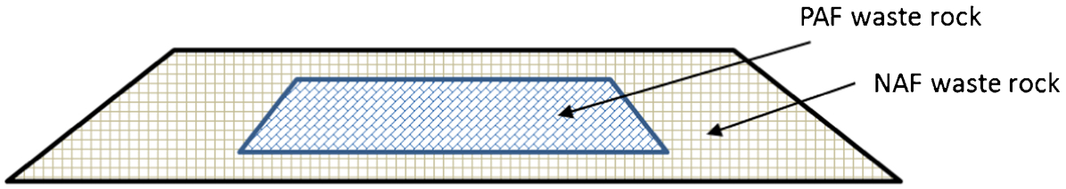
Simplified cross-section view of a waste rock dump with potentially acid forming (PAF) waste rock fully encapsulated by non-acid forming (NAF) waste rock (after Williams et al., 2006)
As a result, an optimised waste rock placement schedule would play a crucial role in achieving not only cost minimisation but also environmental sustainability. Additionally, the placement of low-grade ore (LGO) can be included as a part of the placement schedule, such that its future access remains possible.
Sommerville and Heyes (2009) attempted to optimise waste rock placement by selectively handling different rock types, enabling waste rock dump rehabilitation to be progressively carried out. The disadvantage is that the heuristic-based methodology does not provide the optimum solution. Topal et al. (2009) investigated the problem using a mixed integer programming (MIP) model, which is a scientifically proven method to search for the optimum solution under multiple criteria. The MIP model constructed aims to minimise overall waste rock haulage time. However, it does not consider material re-handling or enforcing PAF rock encapsulation, which is the major flaw of the study. The solution is generated by solving the problem for each single time period, which is a violation to global optimality.
Li et al. (2012) revisited this work and developed an MIP model to minimise overall waste rock haulage distance, with the options for stockpiling NAF waste rock and enforcing PAF waste rock encapsulation. The short-coming of this MIP model is that haul truck utilisation was neglected. To maximise equipment utilisation for waste rock haulage, Li et al. (2013) modified the MIP model. Test results indicated that all available haul trucks were fully utilised, but much higher cost was incurred, which suggests that the additional constraint cannot achieve the balance between the short haul and effective truck utilisation. Another issue is associated with PAF rock encapsulation. The model forces the entire waste rock dump to be filled to the designed capacity in order to achieve the encapsulation and capping of PAF rock. This may not be feasible if the waste rock dump capacity exceeds the total waste rock volume produced by the open pit. Furthermore, only a lift-by-lift dump construction sequence was investigated in the study, which excludes the possibility of having a multiple tip-head scenario. Therefore, further improvement to the model is required.
In this paper, the two earlier MIP models (Li et al., 2013): the location optimisation (OP) model and the truck balance (TB) model, are revised by refining the flawed constraints controlling truck utilisation and PAF waste rock encapsulation. A new overall balanced (Combo) MIP model is proposed seeking a schedule that considers both haulage cost and truck usage. Most importantly, a multi-lift dump construction sequence is modelled to represent a multiple tip-heads scenario, which is a more flexible waste rock dump construction configuration compared to a lift-by-lift sequence, and the results obtained from the new models are compared with those obtained with the lift-by-lift models.
Modelling of mining and waste rock placement
Open pit mining and hauling waste rock to dumps are linked processes, hence an integrated approach should be adopted. To better understand the extent of the problem, an integrated mining and waste rock placement framework is modelled, as shown in Fig. 2.
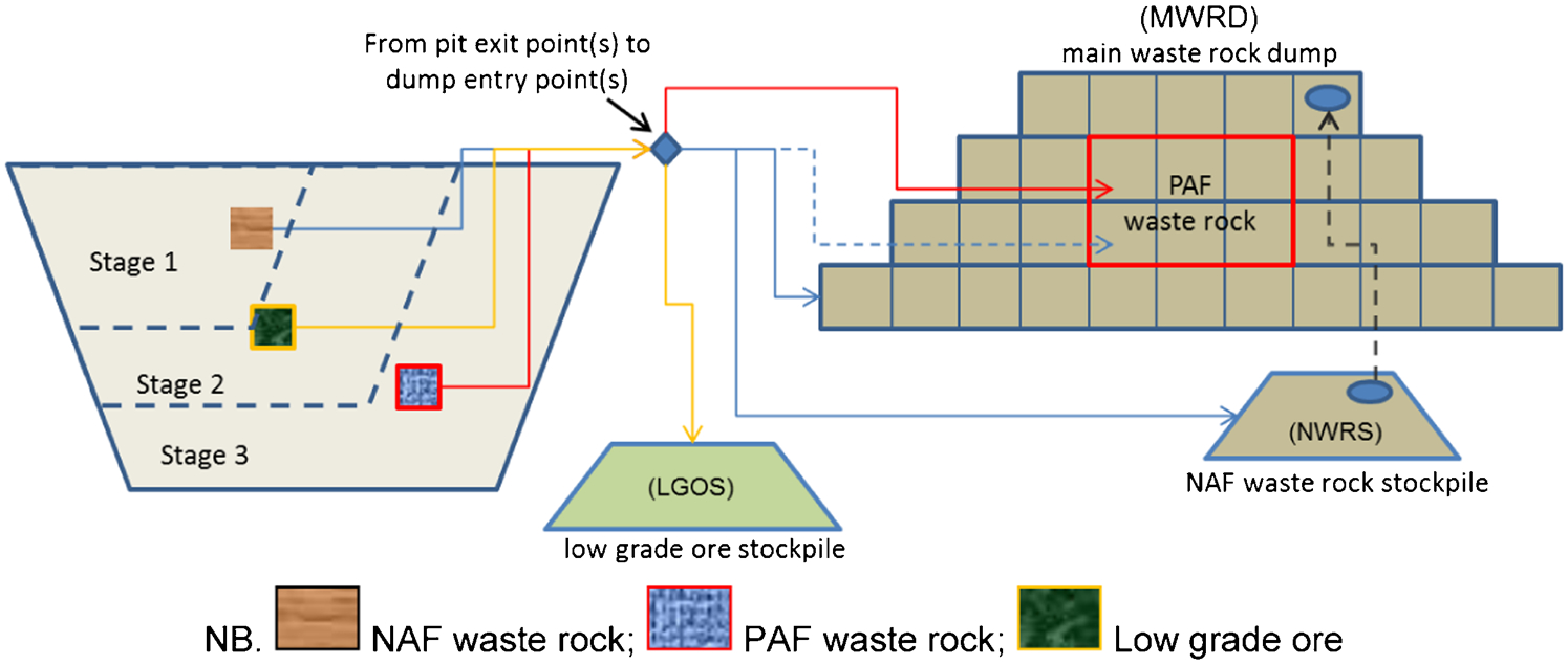
Integrated framework of mining and rock placement
The mining of a large open pit can progress in multiple stages, during which rock blocks are mined in a specific time frame, according to the pre-defined production schedule. The PAF waste rock, NAF waste rock, and LGO are selectively hauled to different dumps, including the main waste rock dump (MWRD), the low-grade ore stockpile (LGOS), and the NAF waste rock stockpile (NWRS), as can be seen in Fig. 2.
The general material segregation rules are listed below:
Low-grade ore is to be stored in a designated LGOS so that future access is maintained.
Potentially acid forming waste rock is only allowed to be dumped in the centre of the MWRD, as illustrated in Fig. 2, to minimise contact with air and water and reduce the potential for AMD.
Non-acid forming waste rock is predominantly to be dumped in the MWRD, with the option to store it in the NWRS for the future encapsulation of PAF waste rock in the MWRD. Non-acid forming waste rock stored in the NWRS can be re-handled to the MWRD for the purpose of encapsulation. However, it will incur extra cost.
To manage rock allocation, the waste rock dumps are divided into smaller dump blocks, similar to mineable blocks defined in the open pit block model. Each dump block represents a particular dumping location and has a nominal volumetric capacity. The dump blocks can be uniquely identified by the rock dump name, and its centroid easting (x), northing (y) and elevation (z) co-ordinates.
The haulage route is from a mining block within an open pit to a waste rock dump block, and crosses intermediate points such as physically permitted staged pit exit points and one of the possible dump entry points, which are dependent on the pit progression and waste rock dump designs. All potential haulage routes are considered and are measured by an equivalent flat distance that reflects the slower truck speed on (up or down) ramps.
The core problem is scheduling the volumetric movement of rock from a mining block to its destination(s), via a choice of physically permitted staged pit exit point(s) and dump entry point(s), such that the associated haulage distance and any NAF waste rock re-handle are minimised and PAF waste rock is encapsulated. In order to solve this problem, three MIP models are proposed. The scheduling results are analysed and presented in this paper.
Mixed integer programming model mathematical formulation
A series of indices, sets, parameters and variables are used in the mathematical formulation, which are defined in the following section.
Indices
The following indices are required in the formulation of the model:
t = time periods;
p = available pits;
b = mining blocks;
p1 = staged pits;
e1 = staged pit exit points;
n = rock dumps, i.e. MWRD, LGOS, and NWRS;
e2 = rock dump entry points;
d = dump block location, containing information on the particular rock dump, its easting, northing, and elevation; and
d′ = precedent dump blocks of the dump block d.
Sets
The following sets are required in the formulation of the model:
 = set of mining blocks located in pit p, to be removed during time period t;
Ep1 = set of pit exit points from staged pit p1;
En = set of dump entry points to n rock dump;
M = set of dump blocks in MWRD;
R = sub-set of M, representing the pre-defined reserve for PAF waste rock in the centre of the MWRD, which are permitted to receive both PAF waste rock and NAF waste rock;
F = set of dump blocks within the LGOS. This group of dump blocks are permitted to receive LGO only;
P = set of dump blocks within the NWRS. This group of dump blocks are permitted to receive NAF waste rock only. The NAF waste rock stored is allowed to be re-handled;
MF = set of dump blocks in either set M or set F;
MP = set of dump blocks in either set M or set P;
MR = set of dump blocks located immediately above the reserve for PAF waste rock. This group of dump blocks forms the cover of the PAF waste rock;
PS = set of precedence dump blocks under lift-by-lift construction sequence; and
PM = set of precedence dump blocks under multi-lift construction sequence.
Parameters
The following parameters are required in the formulation of the model:
Ub = bulk volume [measured in bank cubic metres (BCM)] of a mining block b;
Gb = grade of a mining block b;
G0 = cutoff grade to determine whether a block is LGO or waste rock;
Ab = reactivity of a mining block b;
A0 = cutoff reactivity value to determine whether a block is PAF or NAF waste rock;
Cd = volumetric capacity of a dump block d;
S = swell factor;
r = discount rate, assumed to be 12%;
Db,e1 = equivalent flat distance from a mining block b to staged pit exit point e1;
De1,e2 = equivalent flat distance from a staged pit exit point e1 to rock dump entry point e2;
De2,d = equivalent flat distance from rock dump entry point e2 to dump block d;
Dn,d = equivalent flat distance from rock dump n, i.e. n = NWRS, to dump block d;
TC = truck annual capacity, measured in BCM m; and
TNt = number of haul trucks available in time period t.
Variables
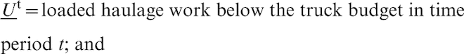
The following variables are required in the formulation of the model:
 = rock volume hauled from mining block b, via pit exit point e1 and rock dump entry point e2, to dump block d, in time period t (linear variable);
 = NAF waste rock re-handled from NWRS to dump block d in time period t (linear variable);
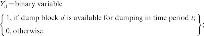
 = filling status of dump block d at the end of a time period t, ranging from 0 to 100% (linear variable);

Location optimisation (OP) model
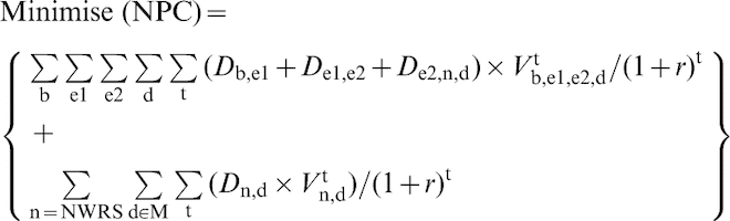
The base or OP model aims to minimise the overall haulage distance and re-handle volume to minimise the net present cost (NPC) over the life-of-mine. The volume of rock hauled and the loaded distance travelled are included in the cost estimation, given in equation (1). The cost factor used is 1 cent per loaded flat metre per BCM handled, and the time value of money is considered, with a discount factor applied
Mining schedule constraints
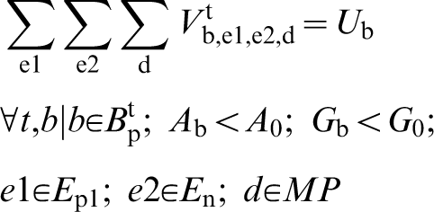
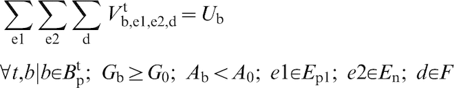
The mining schedule constraints (2)–(4) ensure complete removal of a mining block during the scheduled time period, and also provide guidance on the selection of the appropriate rock dumps to satisfy the material segregation rules
Dump block capacity constraints
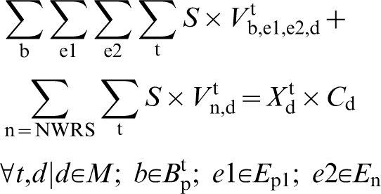
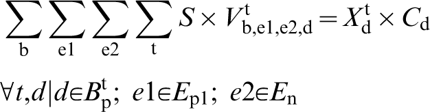
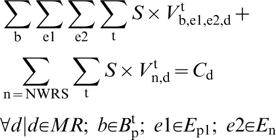
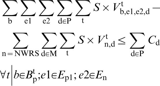
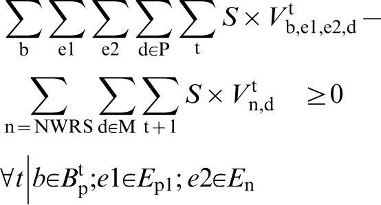
The dump block capacity constraints (5) and (6) monitor the percentage filling of every dump block within the MWRD, the LGOS and the NWRS during each time period. Constraint (7) ensures the dump blocks located on the immediate top of PAF waste rock reserve to reach their capacity, such that PAF rock encapsulation is achieved at the end of mine life
Stockpiling and re-handling constraints
The NWRS and re-handle constraints (8)–(10) regulate the material flow to and from the NWRS

Lift-by-lift dump construction dependence constraints
To generate a feasible rock placement schedule, a logical rock dump construction sequence must be modelled. The lift-by-lift construction sequence is controlled by the inter-lift dependence condition, which requires that all of the dump blocks in a lift are completely filled before allowing dumping in the lift above. An illustration of this condition can be seen in Fig. 3.
Dependency condition for lift-by-lift dump construction sequence
The lift-by-lift construction sequence in the MWRD is controlled by constraints (11) and (12), and the sequence in the LGOS is controlled by constraints (13) and (14)
Multi-lift construction dependence constraints
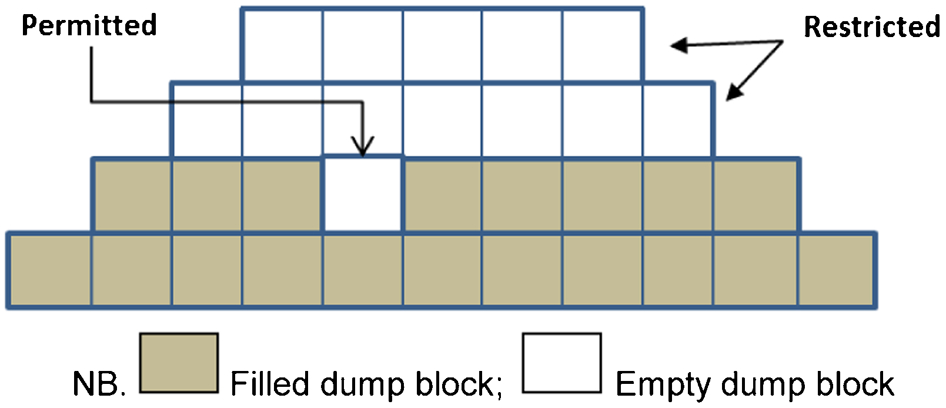
The multi-lift construction sequence allows dumping to occur in multiple lifts within a given rock dump. The sequence is controlled by the inter-block dependence condition, which applies to every dump block from the second lift onwards. This condition is illustrated in Fig. 4. A dump block will become available only if all nine dump blocks below are completely filled. All dump blocks in the first lift are always available for rock dumping.
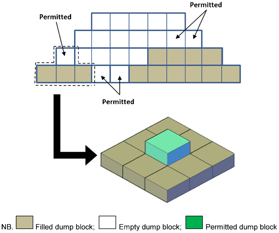
Dependency condition for multi-lift dumping sequence
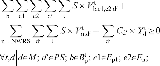
The multi-lift dump construction sequence is controlled by constraints (15) and (16)


Non-negativity and integrality constraints
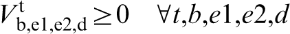
Constraints (17)–(20) enforce non-negativity and integrality of the variables, as required


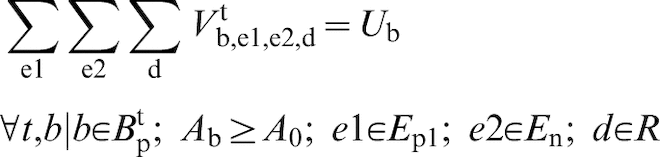
Truck balance (TB) model
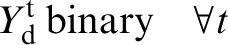
A rock placement schedule details the volumetric rock movement and the associated haulage distance for each mining block. The product of the two equates to the required loaded haulage work, measured in BCM m and is carried out by haul trucks, which have a maximum work capacity in each year. However, the required loaded haulage work from the placement schedule may not match the truck budget, resulting in either under-trucked or over-trucked situation. The mismatch will translate into opportunity cost, which leads to the development of the first MIP model variant, named the TB model. It does not optimise the haulage distance or the volume of re-handle, but rather minimises the opportunity cost, as indicated in objective function (21), so that truck utilisation can be maximised. Meanwhile, the cost factor and discount rate are also applied as the same in OP model.
Truck balance model specific constraint
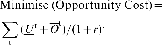
Constraint (22) is the specific constraint for the TB model forcing the required loaded haulage work from the rock placement schedule to equal the available truck work capacity plus (or minus) the amount of under (or over) budgeting. It ensures that the resulting placement schedule mitigates any under or over budget, such that the available truck work capacity is fully utilised
Constraints (23) and (24) state the non-negativity condition for the newly introduced variables for the TB model

Overall balanced (Combo) model
The second variant MIP model is named the Combo model, which is developed by combining the objectives of the OP and TB models. The objective function (25) aims to generate a balanced rock placement schedule considering haulage and re-handle cost, and opportunity cost in truck budgeting
Combo model specific constraint
From a truck budgeting perspective, the impact of over-budgeting is less severe than under-budgeting, as the potential delay because of haul truck shortage may lower the production rate. Therefore, constraint (26) gives some degree of freedom, by allowing a mismatch to occur, but guarantees that the required loaded haulage work from the rock placement schedule is satisfied.
Implementation of MIP models
A hypothetical mine site was created using the mine design package Vulcan (Adelaide, SA, Australia), for MIP model implementation. The mine layout is illustrated in Fig. 5, in which a square-shaped waste rock dump is adopted in order to generate regular-shaped dump blocks.
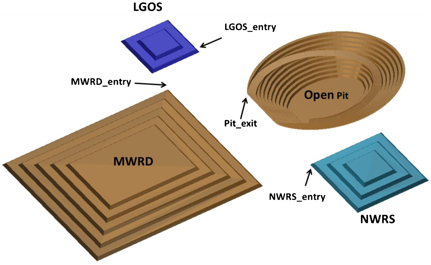
Conceptual layout of rock dump and stockpiles, and locations of pit exit and dump entries
The MWRD is designed to the final landform shape, with all PAF waste rock fully encapsulated by NAF waste rock. The LGOS and NWRS are based on the maximum allowable footprint, with the actual required size to be determined by the MIP models. Each rock dump or stockpile is divided into a number of regular dump blocks, with the details summarised in Table 1. The total number of dump blocks is 969, and the overall capacity is 14·24 million m3.
Number of dump blocks in each rock dump
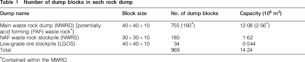
Contained within the MWRD.
The open pit contains 2547 regular waste rock blocks measuring 20×20×10 m (length, width and height, respectively). These blocks are categorised into three types: i.e. NAF waste rock, PAF waste rock and LGO, which need to be segregated when choosing the dumping location(s). The yearly waste block mining schedule is summarised in Table 2. The waste block mining rate varies between 429 and 690 per annum, reflecting a variation in waste stripping.
Number of waste blocks in mining schedule and break down of material types
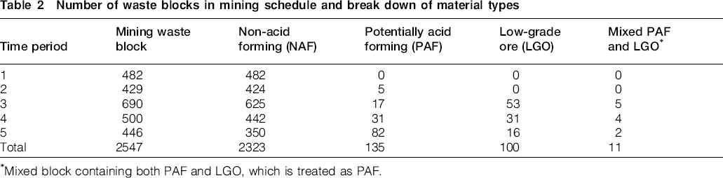
Mixed block containing both PAF and LGO, which is treated as PAF.
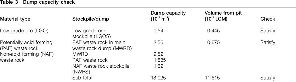
The swelled volume of waste rock is calculated based on a net swell factor of 1·25. A preliminary check of the capacity of each dump, given in Table 3, indicates that each type of rock can be accommodated in the current rock stockpile/dump design.
Dump capacity check
The MIP models are programmed in the mathematical programming language AMPL, and the OP problem for this case study is solved by IBM ILOG CPLEX 12·4. Three MIP models are combined, with two dump construction sequences i.e. lift-by-lift and multi-lift rock dump construction sequences, resulting in six MIP problems. Each problem involves more than two million variables, as shown in Table 4. The problems are certainly beyond the capacity for manual solution, but can readily be solved by a PC with the specification of 2·8 GHz CPU with 24 GB RAM.
Mixed integer programming (MIP) problem size and solution time
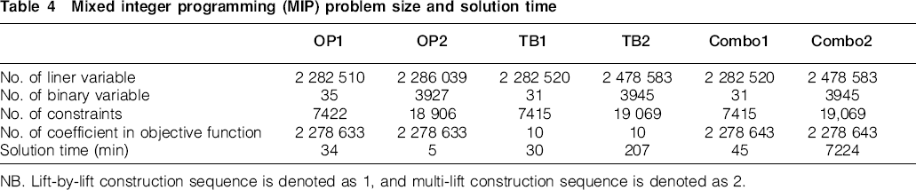
NB. Lift-by-lift construction sequence is denoted as 1, and multi-lift construction sequence is denoted as 2.
Results and analysis
The solution of the key decision linear variables forms a detailed rock placement schedule, including a rock volume movement schedule, a NAF waste rock re-handle schedule, and an annual dump block filling schedule, as presented in Tables 5–7, respectively. An example interpretation of the results is given in the first row data of each table.
Rock volume movement schedule

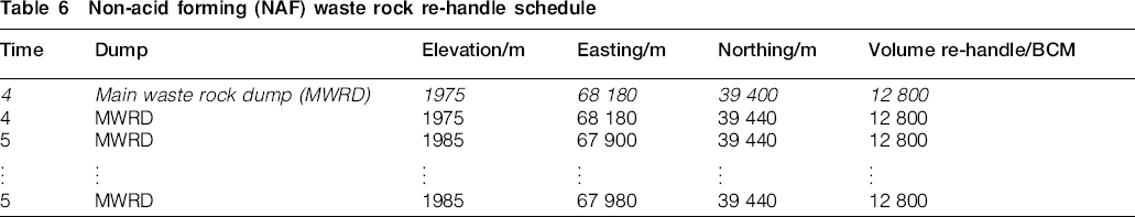
Non-acid forming (NAF) waste rock re-handle schedule
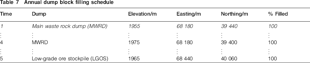
Annual dump block filling schedule
Row 1 in Table 5 can be interpreted as follows: during time period 1, 800 BCM of rock is hauled from block 478 located in test_pit via exit_e1 to MWRD using dump entry MWRD_e1 to a dump block, with its centroid located at elevation 1955, easting 68 180 and northing 39 440.
Row 1 in Table 6 can be interpreted as: during time period 4, 12 800 BCM of rock stockpiled in NWRS is to be re-handled to a dump block within the MWRD, with its centroid located at elevation 1975, easting 68 180 and northing 39 400.
Row 1 in Table 7 can be interpreted as: at the end of time period 1, the dump block with its centroid located at elevation 1955, easting 68 180, and northing 39 440 within MWRD is filled to 100% of its capacity.
A total of six rock placement schedules are generated on solving the six MIP problems. In order to compare the different effectiveness of each model, the loaded haulage work requirement, the estimated haulage cost, and the re-handle of rock are calculated and analysed.
Loaded haulage work requirement
The loaded haulage work links the volumetric rock movement and the associated haulage distance, to form an explicit rock placement schedule. The resulting haulage work required under the lift-by-lift dump construction and multi-lift dump construction sequences are presented in Figs. 6 and 7, respectively.
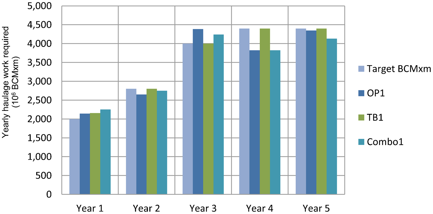
Yearly haulage work requirement under lift-by-lift rock dump construction sequence
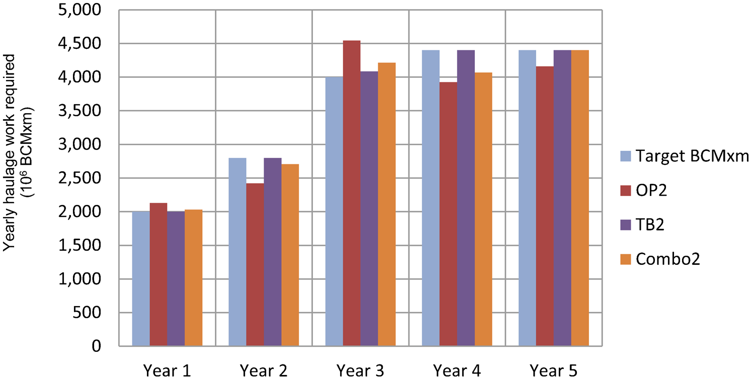
Yearly haulage work requirement under multi-lift rock dump construction sequence
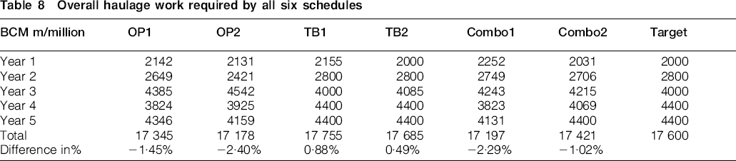
Regardless of the rock dump construction sequence, it appears that the OP model performs best in minimising the required haulage work, but deviates from the target truck capacity. In contrast, the TB model yields the best match to the target capacity, and the Combo model performs between that of the OP and TB models. Details of the total haulage work required by all six schedules are summarised in Table 8, which shows that the schedule generated by the TB models will result in less than 1% difference from the target overall, which is the best among the three models in terms of matching the budget.
Overall haulage work required by all six schedules
Haulage cost estimated by six schedules
The haulage cost is estimated using a cost factor of 1 cent per BCM per flat m hauled, with a discount rate of 12% applied annually. The estimated cost for each rock placement schedule is shown in Fig. 8.
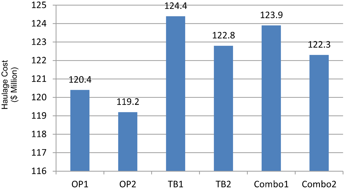
Estimated haulage cost of six rock placement schedules
It can be seen from Fig. 8 that the estimated haulage cost under a lift-by-lift dumping sequence is higher than that under a multi-lift dumping sequence, for all three models, which proves the flexibility and potential cost savings of multi-lift dumping. It again proves that the haulage cost associated with the OP model schedule is the lowest among the three models tested.
Volume of re-handle
The total re-handle volume determined by the MIP models is derived from the NAF waste rock re-handle schedule, as shown in Table 6. A comparison of the results is illustrated in Fig. 9. It is observed that the schedule from TB models need to re-handle the greatest amount of rock, as NAF waste rock re-handle is not the OP focus. In comparison, the OP and Combo models schedule need to re-handle much less waste rock. An ideal solution, with no re-handle required, is generated by the OP model under multi-lift dumping.

Comparison of waste rock re-handle by six rock placement schedules
It is evident that multi-lift construction sequence has obvious advantage over the lift-by-lift construction sequence, as the re-handle volume determined by OP1 and TB1 is higher than that of by OP2 and TB2, respectively. The NAF rock re-handle option is designed primarily for encapsulating the PAF waste rock. Hence, it could be interpreted that multi-lift construction sequence will allow prompt progressive capping of PAF waste rock as a result of its greater flexibility.
In regard to the results generated by the Combo model, it is noted that a larger re-handle volume is required for the multi-lift construction sequence. This is because both haulage distance and truck mismatch components are considered in the objective function. Haulage minimisation will schedule rock to be placed closer to the pit, resulting in low-loaded haulage work. However, this will increase the truck mismatch from the budget, and adversely impact the overall objective value. Therefore, the more flexible multi-lift construction sequence is able to mitigate this by increasing the re-handle volume to achieve higher loaded haulage work, which minimises the mismatch in the truck budget. Meanwhile, it still ensures that the overall estimated haulage cost from Combo2 is less than that of Combo1, as indicated in Fig. 8.
Conclusions and recommendations
The aim of the research is to develop a tool to generate optimised rock placement schedules, integrated with the mine production schedule and environmental constraints. A base MIP model, along with two variants are discussed and implemented for a hypothetical mine site. Each problem contains more than two million variables. They are solved by IBM ILOG CPLEX and the detailed rock placement schedules are automatically generated, including the re-handle schedule for NAF waste rock. This tool would assist mine planning engineers in mine design and improve the environmental performance of a waste rock dump.
The analysis results indicate that of the three models discussed, the OP model schedules are best at minimising the overall loaded haulage work, resulting in the minimum haulage cost, and the minimum re-handle volume. The TB model schedules yield the best match with the truck budget, but incur the highest haulage cost and re-handle volume. The Combo model schedules rank between these two extremes as both haulage distance and truck budget are considered.
The other finding is that the multi-lift dump construction sequence is more flexible than the lift-by-lift dump construction sequence, resulting in a lower estimated haulage cost and reduced rock re-handle. However, it requires regular-shaped dump blocks. This could be difficult to implement in reality. Ore haulage is excluded in this study, although it could be an important part in planning the haul truck budget, hence further work is required. In addition, different weighting factors can be introduced to adjust the importance of short distance haul and truck mismatches.
One limitation of the study is the assumed deterministic inputs i.e. the PAF and NAF waste rock volumes in the production schedule. The chemical composition of the rock to be mined is heavily dependent on the sampling frequency and geological interpretation, which may not result in accurate classification of the rock types. Some scholars (Dimitrakopoulos and Ramazan, 2008; Goodfellow and Dimitrakopoulos, 2013) realised this potential risk, and started to utilise stochastic methodology in mine planning to reduce the impact of geological uncertainty. Similarly, future study of rock placement should also focus on developing stochastic-based OP models, in order to address the uncertainties associated with the resource model.
Footnotes
Acknowledgement
The authors thank the Minerals and Energy Research Institute of WA (MERIWA), AngloGold Ashanti, Kalgoorlie Consolidated Gold Mines, and Rio Tinto for their financial support, and also for their approval to publish this paper.