
Abstract
The heterogeneous character of fibrous composite materials implies mechanisms of damage that are frequently associated, at least at the micromechanical level, with the generation of interface cracks and, thus, with interfacial fracture mechanics. The particular case of matrix/interfibre failure, typically appearing in impact problems and in cross-ply laminates, and caused by a dominant traction acting transversely to the fibres, is directly associated to the appearance and growth of cracks at the fibre/matrix interfaces that eventually lead to macrofailure. The present work studies the evolution of this mechanism of damage under compression and compares the results obtained for two different bimaterial systems: glass fibre–epoxy matrix and carbon fibre–epoxy matrix. To this end, a boundary element model of a single fibre cell is performed, and its results are analysed using the concepts derived from interfacial fracture mechanics. The conclusions obtained establish the morphological differences existing in the generation of this mechanism for both material systems, supporting the idea of a weak dependence of the development of the interfibre failure under compression on fibre elastic properties.
Introduction
When unidirectional laminates are tested under transverse compression and the angle of failure is measured, a value of ∼53° is found,1 a fact already pointed out by other authors (e.g. Puck and Schürmann2 and Christensen and de Teresa3). A priori, and from a linear elastic point of view, no macromechanical explanation for this orientation being different from 45° suggests itself.
This evidence motivated the authors of this work to study the generation at micromechanical level of transverse failure under compression, which is commonly known as matrix/interfibre failure (under compression). As the particular case of interfibre failure under transverse tension had already been the object of several micromechanical studies by the authors,4–6 based on the generation of interface cracks and concluding with the establishment of the micromechanical phases that lead to the orientation of the macroplane of failure, the case under transverse compression was undertaken following the same procedure. 1 , 7 To this end, boundary element single fibre models were employed, and interfacial fracture mechanics concepts8 applied for the analysis of the results on a glass fibre–epoxy matrix system. Notice that other authors, for instance Quesada et al., 9 consider the possibility of additional mechanisms of damage not initially associated to the generation of interface cracks.
These studies that are related to the compressive case have made it possible to understand the initiation of failure at the micromechanical scale as well as its later progress for a glass–epoxy system in the case of dilute packing and relatively weak interfaces, which leads to macrofailure of the material and is summed up in the next paragraph.
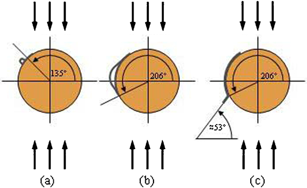
The interfibre failure under compression, typically appearing in impact problems and caused by a dominant compression acting transversely to the fibres, starts with the appearance of small debonds at the fibre/matrix interfaces. The initial defects present a non-symmetric morphology: a small ‘bubble’ at the lower crack tip and a contact zone at the upper crack tip (see Fig. 1a). In the first period, these initial debonds grow unstably along the interfaces (interface cracks) following the ‘open’ (lower) crack tip. This period ends when the cracks have reached a certain length at the interface (Fig. 1b). From that moment on, the growth of the interface crack becomes stable, which favours the occurrence of a different stage of the mechanism of failure: the kinking of the crack and its propagation through the matrix. Thus, the interface crack suddenly changes its direction of propagation (Fig. 1c), kinking into the matrix following an orientation angle of ∼53° from the direction perpendicular to the load, which agrees with the experimental evidence.
Numerically predicted phases of damage under compression transverse to fibres
Now that the different phases of the initiation of the mechanism of damage are established, it is time to evaluate their dependence on the material properties. In particular, in the present work, the development of interfibre failure under compression is revisited to perform a comparison between two different bimaterial systems, i.e. glass fibre–epoxy matrix and carbon fibre–epoxy matrix, aiming to analyse the dependence of the results obtained so far on fibre elastic properties.
Modelling
The numerical analysis is performed using a numerical tool based on the boundary element method (BEM)10 that permits a numerical analysis of plane elastic problems, including frictionless contact and interface cracks, in a similar way to that described in Blázquez et al.11 for planar problems and Graciani et al.12 for axisymmetric problems.
Two BEM models are used in this analysis. The first BEM model, used in the sections on ‘Growth of interface crack’ and ‘Kinking of interface crack’, consists of a single fibre configuration that, under the plain strain hypothesis and subjected to a remote transverse compressive load, incorporates a debonding (circular shape crack) situated at the fibre/matrix interface (Fig. 2a). The BEM model permits the detection of possible contact between fibre and matrix along the debond. The second BEM model, used in the section on ‘‘Kinking of interface crack’, is a modification of the first and is able to analyse the appearance of a kinked crack in the matrix, daughter of the interface crack (Fig. 2b). As happens for the interface crack, contact is allowed between nodes of both faces of the kinked crack.
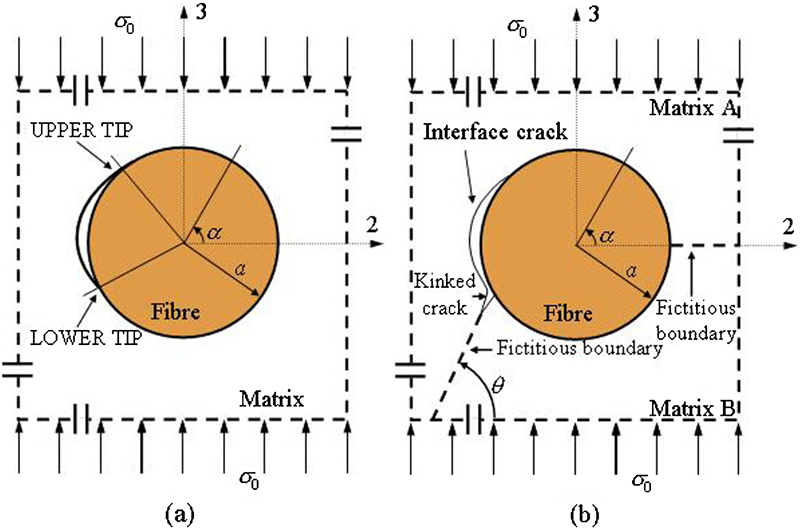
Single fibre model with a interface crack and b kinked interface crack
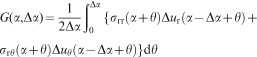
To characterise the problem from the fracture mechanics point of view, the energy release rate G is used. Adapting the virtual crack closure technique13 to the circumferential crack case, when the crack propagates from a certain crack tip position represented by the angle α to α+Δα (Δα being much smaller than the crack length), gives
G is calculated in the section on ‘Kinking of interface crack’ using the virtual crack closure technique for the kinked crack, as was already performed for the interface crack. The virtual crack step length used is 0·01a, with a being the fibre radius. Obviously, this kinked crack progresses following the classical fracture mechanics conditions of a crack in a homogeneous material. 8 , 14
Two bimaterial systems are considered in the present paper: a glass–epoxy system and a carbon–epoxy system. The linear elastic properties of these materials are listed in Table 1.
Elastic properties of materials considered
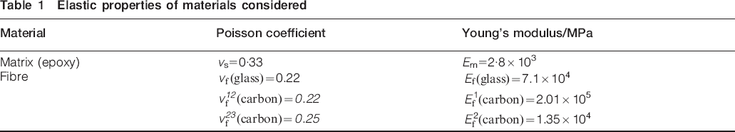
Plane strain state has been considered, and effective elasticity properties for the isotropic in-plane problem are evaluated for isotropic materials, i.e. glass and epoxy, as E′ = E/(1−v2) and v′ = v/(1−v), and, for the transversely isotropic material, carbon, as E′ = E2/(1−v12v21) and v′ = (v23+v12v21)/(1−v12v21).
The geometry is defined by the fibre radius a = 7·5×10−6 m, and the dimension of the external boundary of the matrix side that has been taken equals to 10−3 m. Dimensionless results for G are presented in all cases and obtained, following Toya's approach,
15
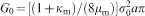
, 16 by dividing the dimensional values G by
Interfibre failure under transverse compression
Micromechanical phases of the interfibre failure under compression will be analysed in this section for both a glass–epoxy and a carbon–epoxy systems. In what follows, the initiation of the mechanism of damage is assumed to take place at the interface based on its consideration as the weakest part of the composite.
Damage initiation at interface
Analysis of the stress state around a fibre with an undamaged interface has already proved to be a way to locate the initiation of damage at the interface.5 Thus, assuming the situation of external compression acting over an initially undamaged interface (see Fig. 3a), an analysis of the stress situation surrounding the fibre has been performed, making use of Goodier's analytical expressions,17 rewritten in terms of Dundurs’ bimaterial parameters α and β, 18 by Mantič.19 Goodier's solution is appropriate in view of the relative dimensions of the fibre and the surrounding matrix. The values of α and β for the bimaterial systems employed in the present work are αglass/epoxy = 0·919, αcarbon/epoxy = 0·624, βglass/epoxy = 0·229 and βcarbon/epoxy = 0·136. Notice that α, β = 0 means homogeneous material and also that larger values of α and β correspond to more dissimilar elastic bimaterials.
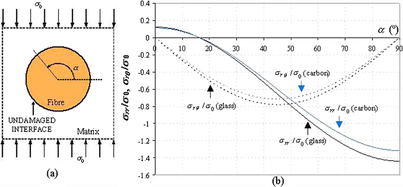
a single fibre scheme for undamaged interface and b radial stresses σrr and shear stresses σrθ at undamaged fibre/matrix interface versus angle α
The results obtained for both glass fibre and carbon fibre systems are presented in Fig. 3b, where radial stresses σrr and shear stresses σrθ at the interface are plotted versus the angular position α (Fig. 3a). Owing to symmetry, only results for one quarter of the fibre are presented. Similar evolutions are found for both bimaterial systems, though the stress values are slightly higher for the glass fibre system than for the carbon fibre one (Fig. 3b). This result is probably associated with the fact that glass fibre is transversely stiffer than carbon fibre, which implies larger values of α and β for the glass system than for the carbon system. Recall that α and β are measurers of the dissimilarity of the bimaterial systems. Specifically, the maximum relative differences are 8% (at angle α = 0°) for the radial stress distributions and 9% (at angle α = 45°) for the shear stress evolutions.
The existence of zones of maximum shear stresses, located at angle α = 45, 135, 225 and 315°, is obviously confirmed for both bimaterial systems (Fig. 3b). The radial stress shows compressive character for almost the entire boundary of the fibre, except an area of reduced size centred at α = 0 and 180°, where tensions of small value take place. It can also be observed from the figure that, for both bimaterial systems, the maximum shear stress is ∼7·5 times higher than the maximum tensile radial stress. In view of the relative values of tensile and shear strength of the epoxy matrix,20 it is not farfetched to consider them of the same order. Thus, taking into account the relative values achieved by ear and tensile stress for the material systems considered here, the beginning of the interfibre failure under transverse compression is considered to be controlled by the shear stress, assuming the location of the first debonds at the interface at the areas of maximum shear stress.
In addition, it can be observed that the shape of the shear stress distribution in the surroundings of the maxima is quite flat in a zone of 20° size, so it is possible to assume the length of an initial debond as 10°. This assumption has later been proven to be in accordance with the range predicted by Mantič19 in an analogous analysis of the tension case. Finally, choosing arbitrarily from the four possible areas of damage initiation, a 10° length debond centred at 135° has been considered, for both systems, as the initial debond whose propagation is studied in the next section.
Growth of interface crack
An analysis of the interface crack growth for both bimaterial systems under the action of an external compressive load (Fig. 2a) is carried out in this section. An initial 10° debond centred at α = 135° (where the maximum shear stress is located) is assumed.
Boundary element method analysis of the initial debond makes it possible to calculate the deformed shape produced by the application of a transverse compression for both bimaterial systems. In both cases, it consists of a non-symmetrical configuration foreseeable in the light of the contact model of interfacial fracture mechanics,21 as was explained in Ref. 7. This non-symmetrical configuration is characterised by the existence of a physically relevant contact zone at the upper crack tip (α = 135°) and a physically meaningless (extremely small) contact zone followed by a ‘bubble’ or separation zone at the lower crack tip (α = 140°). This particular morphology can be observed in Fig. 4, where the radial displacements δur obtained for both bimaterial systems are represented over the undeformed situation of the initial debond. Details of the mesh employed for the analysis can also be appreciated in the figure.
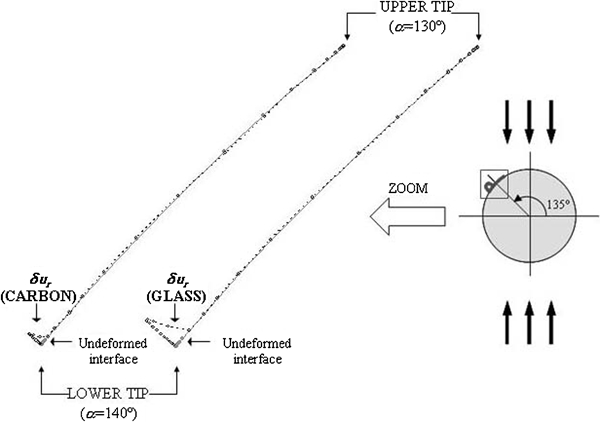
δur situation of original debond
It is clear from Fig. 4 that the ‘bubble’ appearing at the glass/epoxy interface crack is greater than that associated to the carbon–epoxy system, this being caused by the greater ratio of fibre transverse stiffness/epoxy matrix stiffness of the glass system versus the carbon system (see the discussion in the section on ‘Damage initiation at interface’).
With reference to the evaluation of growth of the interface crack, and as was already explained in the section on ‘Modelling’, this is carried out employing the energetic approach of interfacial fracture mechanics and thus the energy release rate G of the interface crack (equation (1)). In this sense, and since the model presented in Fig. 2a shows no symmetry, the study of the growth of the initial interface crack entails the individual evaluation of G for both crack tips (upper and lower) and a subsequent comparison between them in order to distinguish whether the crack growth is symmetrical or, on the contrary, limited to a single crack tip.
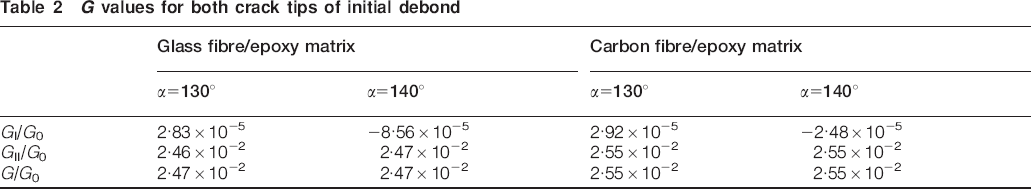
The G values corresponding to both bimaterial systems are presented in Table 2, where it can be checked that G is almost identical for the lower (α = 140°) and the upper (α = 130°) tips of both systems, presents a mode II character and is only slightly greater for the carbon fibre system than for the glass fibre one. This circumstance would lead, in principle, to a symmetrical growth being predicted, but, in view of the aforementioned crack morphology (Fig. 4) in which the ‘bubble’ at the lower crack tip (in opposition to the physically relevant contact zone at the upper crack tip) announces the imminent appearance of mode I behaviour, a preferential growth of the interface crack following its lower tip is suggested. In addition, the possible presence of friction at the contact zone of the upper tip (not considered in this model but included in some previous works by the authors22) supports this hypothesis. This aspect could be especially observable in the carbon fibre system, where the friction coefficient is expected to adopt larger values owing to the rougher character of the debonded interface. Analysis of the subsequent steps of growth confirms the exclusive extension of the interface crack from its lower tip.
G values for both crack tips of initial debond
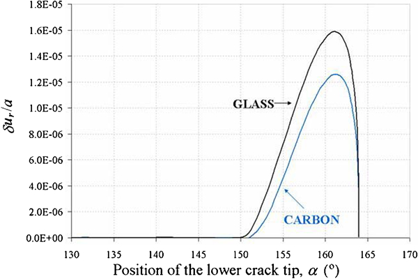
The results of the G evolution at the lower crack tip during the growth of the crack from this tip are shown in Fig. 5 for both bimaterial systems, noting that they are qualitatively similar although presenting slight differences from a quantitative point of view. Mode I reaches higher values for the glass fibre case than for the carbon one at debonding angles, where the ‘bubble’ at the lower tip is most relevant, which happens for α≅180–185°. This fact, again probably associated to the stiffer transverse nature of glass versus carbon, is also noticed in the greater size of the ‘bubble’ detected for the glass system, which happens not only for the initial debond (Fig. 4) but also for the later steps of growth (as shown in Fig. 6, where relative radial displacements δur between both crack lips are plotted at the lower crack tips for a 34° length debond).
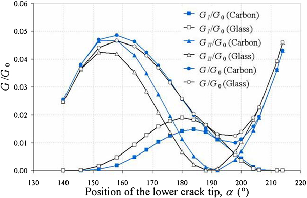
G of lower crack tip of interface crack
δur situation for 34° debond
Continuing with the information included in Fig. 5, the relevant participation of mode II at the initial stage of crack growth is also detected for both cases (consult Table 2 for details), with the values associated to the carbon system being in this case slightly higher than for the glass one. The relative position of the values associated to both systems is inverted when mode II changes to increasing in the last steps of growth, coinciding with the disappearance of mode I. This change in character from mixed mode to mode II redounds in the closing of the end part of the ‘bubble’, which existed at the lower crack tip from the very beginning of growth and increased with the debond length, giving rise to a physically relevant contact zone at the neighbourhood of this crack tip. This contact appearance occurs somewhat later for the carbon case (at α = 206°) than for the glass one (at α = 204°).
With reference to the size of the physically relevant contact zone at the upper crack tip, it has been checked that, for both bimaterial systems, it increases as the debond length does and thus with the position α of the lower crack tip. Besides, and with reference to the comparison between both bimaterial systems, this contact zone is slightly greater for the carbon fibre case than for the glass fibre one. These results for the numerical model appear in Fig. 7, where semianalytical predictions carried out following Gautesen and Dundurs’ approach23 are also included.
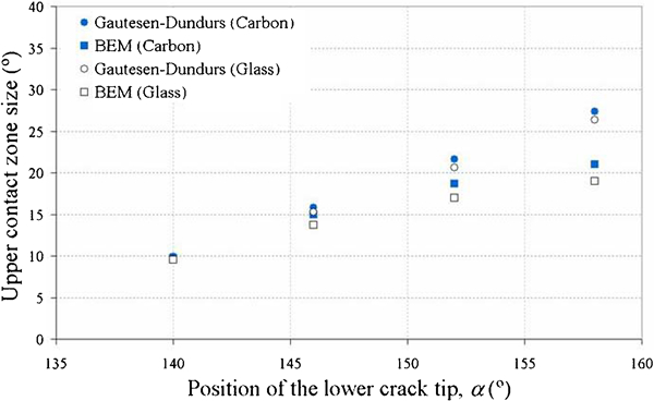
Upper contact zone size evolution for increasing debond length: numerical and semianalytical predictions
Gautesen and Dundurs’ approach makes it possible to calculate the length of the contact zones associated to both crack tips of a straight interface crack making use of Dundurs’ bimaterial parameter β and the ratio shear stress/normal stress existing in the neighbourhood of each crack tip. For the problem presented in this work, shear and normal stresses have been approximated making use of the solution proposed by Goodier17 and already employed in the section on ‘Damage initiation at interface’.
The application of Gautesen and Dundurs’ approach for the particular problem resolved in this paper is limited by the circular shape of the interface crack under study, which excludes the study of large debonds, and also by the physically meaningless character of the lower contact zone, which excludes the study of the lower crack tip. Then, using this tool to predict the size of the upper contact zone (at α = 130°), it can be checked (Fig. 7) that there is an excellent agreement between numerical and semianalytical predictions for very small debonds (when the circular crack assimilates to a straight crack), diverging as the crack grows. Gautesen and Dundurs’ approach also lends support to the numerical results, as it predicts a greater upper contact zone in the carbon fibre case than in the glass fibre one.
After G evaluation for the interface crack at its lower crack tip and in order to be able to perform predictions about the growth of the interface crack, it is necessary to have a reasonable estimation of the critical value of G, Gc, which depends on the evolution of the fracture mode mixity, given by the local phase angle of the stress intensity factor ψK as a function of α. The evolution considered in this work for ψK is calculated as follows
7
, 24
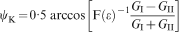
 , and ϵ is the oscillatory index of the interface crack between the fibre and the matrix calculated through

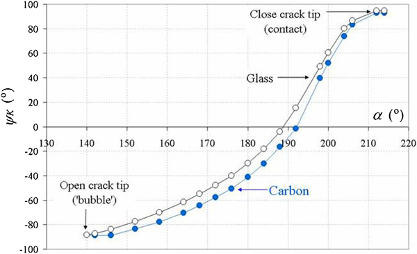
ψK evolution for lower crack tip of growing interface crack
The simplified empirical proposal of Hutchinson and Suo25 is employed in the present work for Gc calculations

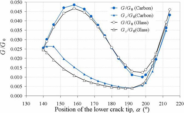
G and Gc for interface crack
As can be observed in Fig. 9, the results provided by the comparison between the values of G and Gc predict an unstable growth of the interface crack up to a lower crack tip position α≅206° for both bimaterial systems. At this point, the growth changes from unstable to stable, matching the appearance of a physically relevant contact zone at the lower crack tip. A further growth of the crack along the interface would necessarily imply an increment of the load and be limited by the presence of friction at the contact zones. In these circumstances, a new phase of the mechanism of damage may take place for both bimaterial systems: the kinking of the crack towards the matrix, which is studied in the next section.
Kinking of interface crack
As explained in Ref. 1, the prediction of kinking of the interface crack towards the matrix, once the period of unstable growth along the interface has finished, consists of two steps: the search for the preferential direction of the incipient crack in the matrix and the evaluation of the possibility of this change in the propagation of the crack.
Referring to the first aspect, the application of a kinking criterion, for instance the maximum circumferential stress criterion,26 at the neighbourhood of the interface crack tip for the position α of termination of unstable growth allows the most favourable direction of the incipient crack in the matrix to be predicted. To this end, and again using the BEM model in Fig. 2a, the circumferential stress σθθ has been calculated at points located on a circumference centred at the crack tip α = 206°, as shown in Fig. 10a. The calculations have been performed for two different radii of the circumference: r = 0·001a and r = 0·01a. The results for both bimaterial systems are presented in Fig. 10b.
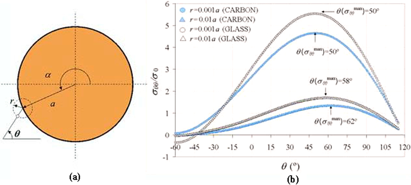
(a) Reference for orientation θ; (b)Circumferential stress state at neighbourhood of α = 206°
Figure 10b includes the distribution of σθθ versus the angle θ defined in Fig. 10a for both bimaterial systems and the radii considered. First of all, the results show that σθθ reaches higher values for the glass fibre system than for the carbon fibre one in the surroundings of the maxima of each distribution. The results also show that the maximum σθθ takes place within the range of θ = 50–58° for the glass fibre system and θ = 50–62° for the carbon fibre system. Both ranges are very similar and above 45° and also contain the experimental macrofailure orientation angle θ≅53° measured by the authors in previous experimental results for a carbon fibre system.1
In addition, analytical calculations have been performed with a view to lending support to the numerical results obtained. First of all, the orientation associated to the maximum circumferential stress
 has been evaluated, making use of the analytical solution by Toya,16 for three different radii r = 0·001a, 0·005a and 0·01a, and compared with their corresponding BEM results for both bimaterial systems (Fig. 11). It must be noted that Toya's analytical solution is based on the open model of interfacial fracture mechanics27 so that, instead of modelling contact (as the BEM model does), interpenetrations between crack faces are allowed. For both bimaterial systems, analytical and numerical values show excellent agreement for the smallest r considered while diverging as r increases. This means that the analytical approach can be applied at the lower crack tip (where the size of the contact zone is very small) but only very close to it, in fact at distances where the solution is still not affected by the physically inconsistent large interpenetration zone (large contact zone in the BEM model) predicted at the upper crack tip. In connection with this last reasoning, it can be seen from the figure that the difference between numerical and analytical results is greater for the carbon fibre case, this apparently being connected to the fact that the extension of the contact zone at the upper crack tip is larger in the carbon fibre case than in the glass fibre one, as was previously commented in the section on ‘Growth of interface crack’.

Comparison between analytical16 and numerical predictions for
A final analytical prediction is graphically represented in Fig. 12, where
 calculated with the BEM model for the maximum and the minimum radii considered are plotted from the fibre boundary. In addition, the analytical predictions, calculated using an expression8 derived from Comninou's contact model solution21 for an infinitesimally small kink, are also included.

Comparison between analytical21 and numerical predictions for
For the case under consideration, α = 206°, the analytical values calculated are
 ° (for the glass fibre system) and
 ° (for the carbon fibre system), with these values representing in fact
 for a vanishing radius r→0. As can be checked from Fig. 12, these results are quite close to the BEM predictions associated to the smallest radius considered.
With reference to the second aspect of the kinking analysis, i.e. the evaluation of the energetic possibilities of kinking occurrence in both bimaterial systems, the values of the energy release rate for an interface crack that has kinked into the matrix Gm from a position at the interface corresponding to α = 206° are calculated making use of the model shown in Fig. 2b and plotted in Fig. 13 for different orientations θ of the kinked crack within the range [45°, 60°]. The length considered for the incipient crack in the matrix is 0·013a (the minimum value permitted by the discretisation employed). In this figure, the value of the energy release rate associated to the crack at the interface Gint for α = 206° is also included.
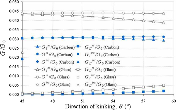
Gm and Gint versus θ
It can be seen in Fig. 13 that, for both bimaterial systems, mode I clearly dominates the Gm values, which are higher than Gint for all orientations considered [∼140% (carbon case) and ∼150% (glass case)], whereas Gint has pure mode II character. This result, combined with the assumption of similar values for
 and
and
 (in accordance with Ref. 1), would support the kinking of the interface crack towards the matrix. It can be also checked, using the adequate zoom, that although the Gm values are similar for all orientations considered, the maximum, strictly speaking, is found for θ = 51° in the glass fibre case and θ = 58° in the carbon fibre case.
As a summary of the previous results, the following scenario is predicted: the crack that has previously grown unstably along the interface as far as a position of its lower crack tip of α = 206° changes its propagation and kinks into the matrix in similar preferential ranges for the bimaterial systems considered in this work (θ = 58–58° for the glass fibre system and θ = 50–62, for the carbon fibre).
Finally, it is interesting to note that Gm values of the glass–epoxy system are greater than those associated to the carbon–epoxy system for the whole range of kinking directions considered (Fig. 13). In this sense, and since the kinked crack grows through the same material for both bimaterial systems, it can be concluded that the propagation through the matrix under transverse compression occurs easily in the glass–epoxy system. This is also reinforced by the results previously obtained in the circumferential stress analysis: this stress was greater in the glass fibre case than in the carbon fibre case, meaning that kinking initiation may also be promoted by a lower external load in the glass fibre case.
In connection with this, looking through the former stages of the mechanism of damage, the following can be reasoned. First, with reference to the appearance of the first debonds (the section on ‘Damage initiation at interface’), since the shear stress at the undamaged interface, which is identified as the agent responsible for this phase of the mechanism of damage, is greater in the glass fibre case than in the carbon fibre one, an earlier initiation of damage could be expected in the glass fibre case if equal interfacial strength is assumed for both systems or if debonds are considered to appear at the matrix (closed to the fibre/matrix interface), as several authors claim, see for instance Asp et al.28 Note that the consideration of equal interfacial strengths would represent a particular case within the wide range of actual possibilities regarding the agents employed before curing.
Second, and with reference to the interface crack growth, the differences found between both bimaterial systems, as was explained in the section on ‘Growth of interface crack’, are basically of a morphological nature, there not being enough evidence to predict an earlier development of this stage either for the carbon–epoxy system or for the glass–epoxy system. Therefore, in this case, only differences between the interfacial properties associated to both systems, if existent, would determine a clearly preferential growth for either of them. Again, if the same fracture toughness were assumed for both systems or the growth of the interface crack were not settled at the interface itself but close to it in the matrix, no significant difference in the external applied load, which is necessary to promote crack growth, would be found.
Consequently, under the hypothesis established and considering the aforementioned comparison between both bimaterial systems performed for each stage of the mechanism of damage, the present numerical results may indicate a lower external load generating the failure under compression in glass fibre composites than in carbon fibre composites. This conclusion agrees with the experimental references found concerning transverse compressive strength for unidirectional carbon and glass fibre composites.20
Conclusions
The micromechanical phases of the failure under compression have been studied for two bimaterial systems: glass fibre–epoxy matrix and carbon fibre–epoxy matrix. Two single fibre BEM models have been designed with the aim of considering the progress of the initial damage at the interface for both material systems, and results have been analysed in the light of interfacial fracture mechanics.
Regarding the appearance of the first debonds at the interface, the stress state at the initially undamaged interface associated to both systems shows very similar distributions, i.e. only detecting slightly lower stresses for the carbon system.
With reference to the growth of the interface crack, the energy release rate evolutions for the crack at the interface are qualitatively similar. The crack morphology is slightly different in both cases since the size of the ‘bubble’ at the lower crack tip is greater for the glass system than for the carbon system. This fact influences the evolution of the energy release rate along the interface, mainly reducing the level of mode I component in the carbon fibre system, though, again, only slightly. After the comparison with the estimated corresponding critical values of the energy release rate, the predictions of growth at the interface are found to be qualitatively similar for both bimaterial systems.
Kinking of the interface crack towards the matrix is predicted, as well as similar associated ranges for the orientation of the crack towards the matrix for both bimaterial systems. Moreover, the estimated range of preferential kinking orientations detected is above 45° and includes the experimental macrofailure angle in both cases.
It should be remarked that the interface damage mechanism studied in the present work is expected to be relevant, at least from a qualitative point of view, not only for dilute but also, as was discussed in Refs. 1 and 7, for densely packed unidirectional plies if the suitable neighbouring fibre configuration allows it. In this sense, the present approach establishes a base for further more complex studies including several regularly or randomly distributed fibres and covering also subsequent crack kinking towards the matrix. At present, relevant work has already been carried out by several authors using multifibre models concerning the interface crack growth under tension, such as Kushch et al.29 and Távara.30 Nevertheless, similar studies should be performed in the future for the failure under compression, including the kinked crack in the matrix.
Finally, the results obtained in this work lead to the conclusion that, from a qualitative point of view, the micromechanical phases of failure under compression identified so far show a weak dependence on fibre elastic properties in the range of actual and common materials. From a quantitative point of view, the analytical and numerical studies presented in this work constitute a tool able to carry out wider parametrical studies aimed, when compared with suitable experimental results, at measuring the material parameters for a particular bimaterial system.
Footnotes
Acknowledgements
The work was supported by the Spanish Ministry of Education and Science (project TRA2005-06764, TRA2006 08077 and MAT2009-14022) and Junta de Andalucía (project of excellence TEP-02045 and TEP-04501). The authors thank Dr E. Graciani (University of Seville), whose BEM code has been used.
This paper is part of a special issue on Latest developments in research on composite materials