
Abstract
GLARE is a combination of metal and composite materials (known as fibre metal laminates) that was developed as an alternative for aluminium in aerospace applications due to its superior fatigue characteristics and impact resistance. Since GLARE is increasingly being used for aircraft structural components, an interesting scenario is the blast loading of a GLARE structural panel due to an onboard explosion. In the present work, finite element models were generated for various charge sizes for a typical GLARE configuration used for fuselage skin, and the numerical results were compared against experimental results. The numerical models were generated in a way that each ply was modelled separately, and a tie–break contact algorithm was implemented in order to capture debonding between the various layers. Additionally, an elastic plastic material model was implemented for the aluminium layers, and a composite material model with damage parameters that introduces non-linearities into the material model was considered for the composite layers.
Introduction
GLARE, the most known fibre metal laminate (FML), is increasingly being used in structural aerospace components due to its superior crack bridging behaviour under the presence of fatigue cracks. This characteristic allows higher design stresses compared to monolithic aluminium. Moreover, GLARE exhibits a wide range of attractive characteristics, including good impact properties, corrosion behaviour, damage tolerance and fire resistance.1 As they combine a series of advantages over both monolithic materials and conventional composites, FMLs are studied in terms of energy absorption performance and resistance to impulsive loading (blast). Specifically, their behaviour under blast loading was experimentally and quantitatively investigated by Langdon et al.2 and Lemanski et al., 3 where the failure modes of FMLs subjected to blast loading were identified. Moreover, the work published by Langdon et al.4 deals with GLARE subjected to blast loading, and correlations were made between the deflection of the GLARE panel and the impulse applied. From a numerical point of view, Karagiozova et al.5 have established numerical models in order to model the deflection of FML panels subjected to localised blast loading. However, these finite element models were using eight-node solid elements to model the discrete layers bonded with eight-node cohesive elements to model interfacial bonding, which is a technique that is computationally not effective when dealing with large structures and when the blast loading is not localised. In the present work, finite element models were developed for the study of GLARE panels subjected to blast loading, and the results were compared against experimental findings, which were gained under the same boundary conditions within the frame of the FP 6 VULCAN project, using cost effective finite element modelling techniques that can be easily adopted for large aerostructures such as aircraft fuselage panels. The present analysis of the blast behaviour of GLARE panels was performed using the LS-DYNA hydrodynamic code.
Problem formulation
The problem consists of a GLARE panel with dimensions of 800×800 mm clamped at all edges. The GLARE panel consists of GLARE 3 3/2 0·4, which consists of three layers of aluminium 0·4 mm in thickness and two layers of glass prepreg 0·13 mm in thickness. The GLARE grade characteristics used in the present work are given analytically in Table 1. Four load cases were considered, keeping the standoff distance constant at 200 mm and the shape of the explosive (C4 for all cases) spherical. The load cases are summarised in Table 2, whereas a schematic representation of the problem is depicted in Fig. 1.
Schematic representation of problem
GLARE 3 3/2 0·4 specifications

Load cases
Finite element model
For the GLARE panel, a ply-by-ply modelling technique was used, which required modelling each ply separately accompanied by tie–break contact algorithms with friction in order to allow for delamination development. The GLARE laminate consists of Al2024-T3 sheets and 0°/90° glass fibre reinforced polymer (GFRP) laminate made of unidirectional tape FM94-S2 GFRP layers. Thus, it was necessary to investigate two material models that needed to be implemented in the GLARE laminate. For the Al2024-T3 sheets, an elastic plastic material model was used. The purpose of using this material model is twofold. It is a verified, cost effective material model that does not exhibit strain rate dependence, as described in the work carried out by Simmons and Shleyer6 and Veldman et al.7 and verified experimentally. The input constants of the aluminium material model are summarised in Table 3.
Al 2024-T3 input parameters
Furthermore, after examination of preliminary analysis results, the MAT_59 material model of the commercially available LS-DYNA hydrodynamic code was selected for the plies that consisted of the GFRP material. This is an elastic plastic material model with a faceted failure surface valid with shell elements and with consideration of the transverse shear. After tensile failure, only compressive loads and shear can be carried until element removal from the analysis based on limiting strains. A comprehensive review of this material model can be found in Refs. 8 and 9, whereas the input material constants are given in Table 4.
Glass fibre reinforced polymer input values
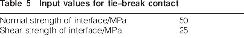
Blast tests described in the literature4 on flat GLARE panels indicated that delamination is possible to develop. This fact led to the necessity to implement delamination in the modelling of the GLARE layers. Delamination in LS-DYNA was implemented via a tie–break contact algorithm. Tie–break contact incorporates failure criteria that, when achieved, release the tied interface between the contacting faces, and the constraint is transformed to a penalty contact interface that allows frictional sliding between the element faces while preventing the penetration of nodes between the parts in contacts. Delamination occurs when the following equation is satisfied
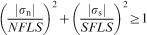
Input values for tie–break contact
The blast load generation was accomplished via modelling the blast wave using the arbitrary Lagrangian–Eulerian formulation. This formulation consists of a Lagrangian timestep followed by a ‘remap’ or advection step. The advection step performs an incremental rezone where the positions of the nodes are moved by a fraction of the characteristic length of the surrounding elements.
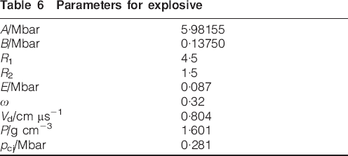
Regarding the modelling of the explosive and detonation products, a material model dedicated to the modelling of high explosives was used (*MAT_HIGH_ EXPLOSIVE_BURN), accompanied with an equation of state (Jones–Wilkins–Lee equation of state). The equation of state is necessary to associate energy, pressure and density


Parameters for explosive
Parameters for air
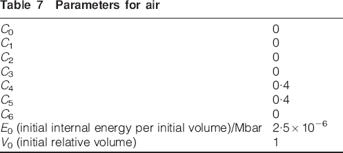
The input parameters for air and explosive were obtained from the literature.12 Figure 2 depicts the whole finite element model, whereas Fig. 3 shows a detail of the explosive part. An exploded view of the GLARE finite element model is shown in Fig. 4.
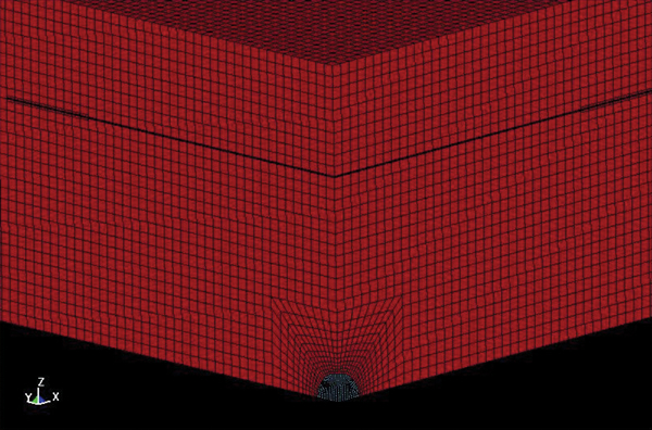
Finite element model
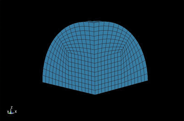
Finite element model of explosive
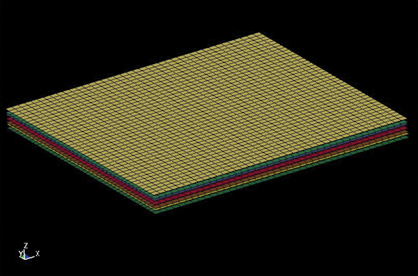
Exploded view of GLARE panel model
Results and discussion
Generally, the following observations are expected from an FML subjected to blast loading according to the literature: 4 , 5
large plastic displacement
stretching and tearing of the aluminium
debonding of the back face
debonding of aluminium internal layers
pitting of the front aluminium face whenever the explosive standoff distance is appropriately small
buckling of the front face.
The experimental procedure was performed at the premises of the Royal Military Academy of Brussels within the frame of the FP 6 VULCAN project, and the results that were used for the validation of the numerical results presented here were strain versus time for a number of panel locations and the permanent final plastic deformation. The strain measurements were acquired by positioning strain gages on the panels, while the permanent deformation of the panels was measured using optical techniques after the experiments.13
Based on the experiments performed for the understanding of the GLARE blast behaviour, the following remarks can be given.
Owing to the mass of the charge and the standoff distance, no rupture was observed on the panels.
Regarding the debonding and delamination between the layers of the panel, no such failure was observed after the panels were cut and examined. Despite the fact that the possibility of interfacial failure in specific areas should not be excluded, since it was observed in the literature,4 no debonding/delamination was observed in the specimen or in the models, since the interfacial stresses were checked.
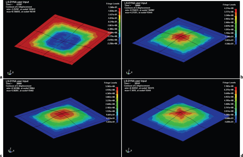
Regarding the plastic displacement and the plastic strain of the aluminium layers, the correlation was performed by two means: by measuring manually the final displacement of the panels and by using strain gages at specific points on the back face of the panels (Fig. 5). The permanent displacement of the panels that were measured manually is given in Fig. 1. The displacement of the centre point of the panels against time as it was calculated numerically is shown in Fig. 6, whereas the numerical results showing the final deformed shape of the panels is shown in Fig. 7. Moreover, the strain gages were used in order to provide additional information regarding the transient behaviour of the panels until the final displacement and to use plastic strain as an additional quantity for the comparison of numerical results against the experimental ones. Unfortunately, a portion of the strain gages attached to the panels were turned off, and only a limited part of the information provided was useful. However, the available experimental results are in good agreement with the numerical results, as can be seen in Fig. 8.
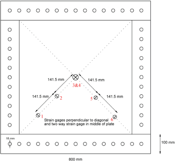
Strain gages position and numbering on panel
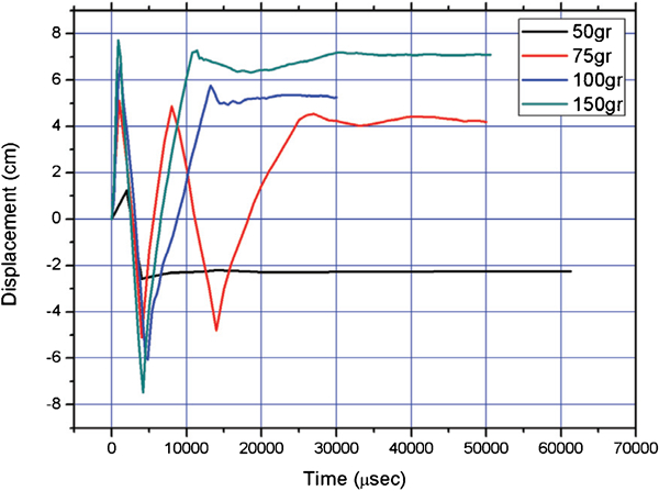
Displacement against time
Final displacement for all load cases
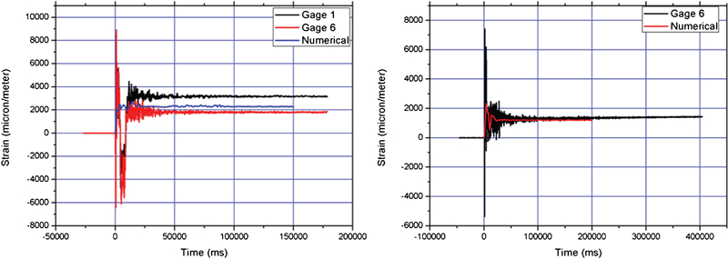
Experimental and numerical strain measurements for load cases of 50 g (left) and 100 g (right)
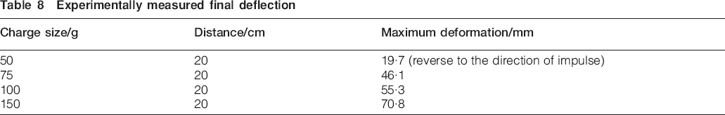
More specifically, as also can be seen in Fig. 6, for the load case of 50 g of C4, the panel exhibits a final deflection that is contrary to the direction of the impulse loading. This phenomenon is described as counterintuitive behaviour in the literature. According to the same literature, this behaviour is typical of the transition from purely elastic to mixed elastic plastic response and is strongly dependent on initial conditions. The same deformation mode was observed numerically and experimentally (Table 8).
Experimentally measured final deflection
This counterplastic deformation behaviour is a phenomenon that is in general difficult to predict numerically owing to its dependence on the initial and boundary conditions. However, the matching between numerical predictions and experimental findings also in this case was an additional value for the numerical work performed since it verifies the validity of the material models used and the initial conditions used as input. For the other load cases, the panels exhibit a typical behaviour, with oscillations at the early stages of the response and a permanent plastic deformation at the end of the experiment. This behaviour can also be verified by the strain measurements performed at the intact strain gages (Fig. 8), where after some oscillations, the strain values are reaching final strain values calculated numerically. This observation, along with the results from the optically measured values of the final plastic deformation, adds even more confidence regarding the validity of the numerical procedure that was applied.
Despite the fact that, as it was discussed earlier, the value of interface stresses did not cause delamination, it was examined whether there is a correlation between plastic strain and interface stresses. This assessment was decided owing to comments presented in the literature, 14 , 15 where, at the bend lines of the material, high shear stresses can cause delamination or debonding. In Figs. 9–12, the maximum plastic strain and the maximum interface shear stresses are depicted for each load case.
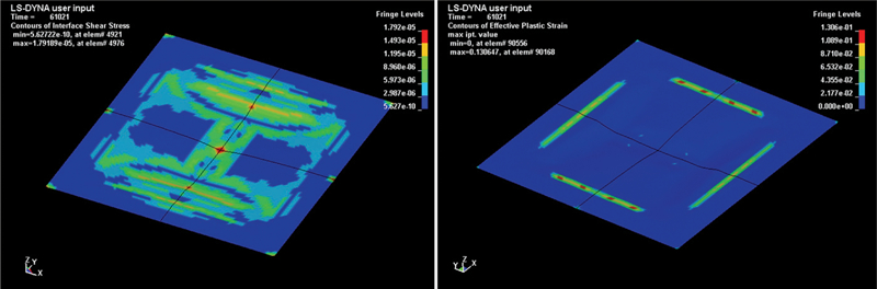
Interface shear stresses (left) and b plastic strain (right) developed on GLARE panel for load case of 50 g of C4
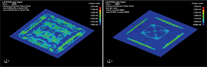
Interface shear stresses (left) and b plastic strain (right) developed on GLARE panel for load case of 75 g of C4
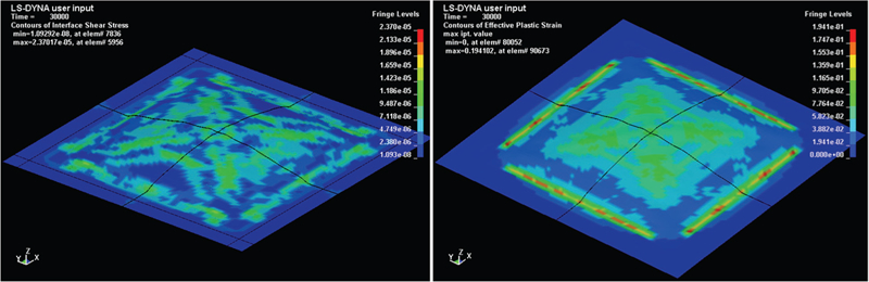
Interface shear stresses (left) and b plastic strain (right) developed on GLARE panel for load case of 100 g of C4
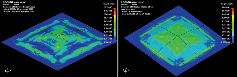
Interface shear stresses (left) and b plastic strain (right) developed on GLARE panel for load case of 150 g of C4
The results show that the maximum values of interface shear stresses correspond to the values where maximum plastic strain is met. As can be seen in Figs. 9–12, the interface shear stresses do not pose a threat to the panel regarding delamination since their values are in the range of 1·7–2·7 MPa. However, this possibly happens owing to the fact that strains in general remain relatively low, well below the failure strains of the composite material.
For larger strains where the failure strains of the GFRP layers will be reached, it is expected that debonding will occur. Moreover, increasing charge mass leads to increased plastic strain and increased development of interface shear stresses, as can be seen in Figs. 9–12, where for the 50 g C4 load case, plastic strain is apparently close to the supports of the panel. For increasing mass of explosive, the yield lines start to appear (Fig. 10), and for the load cases of 100 and 150 g of explosive, the damage is spread in all the area of the panel. This observation leads to the conclusion that even larger quantities of explosive will lead to debonding and/or delamination. Furthermore, the plastic strain supports the indication of where interfacial failure will begin.
Conclusions
In the present work, finite element models were generated, and direct comparisons were made against experimental results in order to establish reliable finite element modelling techniques for problems involving the blast response of GLARE panels. However, owing to the high failure limit of the GLARE panels, no failure limit was established in order to verify all the failure modes of an FML panel. As a future work, the investigation of the failure limit of the panels would help to establish a complete understanding of the behaviour of FMLs under blast loads.
Footnotes
Acknowledgements
The support of the present work by EC DG Research under the frame of the FP6-EU-STREP Project ‘VULCAN’ is gratefully acknowledged. Moreover, the significant contribution of Professor John Vantomme of the Royal Military Academy of Brussels and his group regarding the blast experiments is gratefully acknowledged.
This paper is part of a special issue on Latest developments in research on composite materials