
Abstract
Multiwalled carbon nanotubes (MWCNTs) were incorporated in low density polyethylene (LDPE)/polyolefin elastomer (POE) (mass ratio: 70∶30) blends by melt compounding. The morphology, electrical, mechanical and rheological properties as well as crystallisation behaviour of LDPE/POE/MWCNTs composites were studied. The dispersion of MWCNTs in the matrix was observed by scanning electron microscopy. MWCNTs had a nucleating effect on LDPE/POE blends without influencing the crystal structure of composites, as shown by X-ray diffraction. The network of MWCNTs formed with the increasing content of MWCNTs, leading to the change in electrical resistivity and decrease in melt flowrate. There was percolation threshold existed in electrical resistivity. As content of MWCNT was 10 wt-% in composite, the volume and surface resistivity of composites largely decreased; meanwhile, the dielectric constant of composite increased dramatically. The mechanical properties of composites decreased as the content of MWCNTs increased.
Introduction
Polyethylene (PE) is one of the most widely used polymers in a range of fields due to its excellent processability, high resistance to chemicals and high strength, yet their use are restricted in certain applications because of some defects, e.g. low melting temperature and a tendency to crack when stressed. Ethylene–octene copolymer, one of the polyolefin elastomer (POE), is a good modifier for PE due to its narrow molecular weight distribution and a controlled level of chain branching. Blending two or more polymers is an effective method to improve the performance of plastic materials. Some studies on PE/POE blends were reported1–3 recently. Meanwhile, many kinds of fillers are used to reinforce polymer blends to meet new demands for material, such as clays and carbon fibre. The polymer blends reinforced by fillers combine the advantages of blends and fillers by well dispersion in matrix. The nanoclays,4 short carbon fibers5 and the carbonyl iron powder6 reinforced PE/POE blends were reported recently.
Carbon nanotubes (CNTs) have attracted a great deal of interest in the world due to excellent mechanical, electrical and thermal properties since it was discovered in 1991 by Iijima.7 It was considered as the ideal material filled in polymer. Some researchers8, 9 reviewed the applications of CNTs in different polymers. The CNTs reinforced PE was reported in many studies. Previous studies suggest that CNTs have a nucleating effect on PE;13 meanwhile, the mechanical and electrical properties of PE/CNTs composites are improved with addition of CNTs, such as Young's modulus,10 tensile strength,10 electric conductivity11 and dielectric constant.12 It is shown that the CNTs are able to obviously improve the mechanical and electrical properties of PE. The multiwalled carbon nanotubes (MWCNTs) reinforced low density polyethylene (LDPE)/polyolefin elastomer (POE) blends is expected to have good performance. However, the research on LDPE/POE blends reinforced by CNTs was rarely reported.
Therefore, in this work we prepared LDPE/POE (mass ratio: 70∶30) blends reinforced by MWCNTs via simple melt compounding method. The dispersion of MWCNTs in matrix was observed using scanning electron microscope (SEM) and a combination of differential scanning calorimetry (DSC) and X-ray diffraction (XRD) was used to investigate the crystallization behaviour. The electrical, mechanical and rheological properties of LDPE/POE/MWCNTs composite were also discussed.
Experimental
Materials
LDPE (2426H) was obtained from BASF-YPC Company Limited (Nanjing, China). POE (5061), a copolymer of ethylene and octylene, was supplied by Exxon Mobil Chemical Company (Houston, TX, USA). The MWCNTs were supplied by Chengdu Organic Chemicals Company Limited, Chinese Academy of Sciences. The MWCNTs were prepared using a chemical vapour deposition process. The purity of MWCNTs produced was more than 95%, the average outer diameter was 10–20 nm and average length was 30 μm.
Preparation of samples
Firstly, the LDPE and POE (mass ratio: 7∶3) were fed into the torque rheometer (XSS-300; Shanghai Kechuang Rubber Machinery Company Limited, Shanghai, China) and commingled for 2 min at 140°C, with a speed of 50 rev min−1. Then, melt mixing was continued for 8 min after the MWCNTs were introduced into mixer. A series of LDPE/POE/MWCNTs composites were prepared with 0, 0·3, 0·5, 1, 3, 5 and 10 wt-% MWCNTs. The LDPE/POE/MWCNTs composites were compressed into sheets for testing.
Testing procedures
Scanning electron microscopy
The samples were fractured in liquid nitrogen, and the fractured surfaces were sputtered with Au in vacuum. Then, the surface morphology of samples was examined using a scanning electron microscope (JSM-5610LV; JEOL, Tokyo, Japan), with an accelerating voltage of 15 kV.
Thermal analysis
Thermal analysis was performed by differential scanning calorimeter (Q-200; TA Instruments, New Castle, DE, USA). The mass of sample for differential scanning calorimetry was about 10 mg. To eliminate the thermal history, the samples were firstly heated up to 140°C at a rate of 40°C min−1, and kept for 2 min. Then, the sample was cooled to 0°C at a rate of 5°C min−1 and maintained for 1 min. The second time heating rate was 10°C min−1 as the temperature ranged from 0 to 140°C. The testing was in the flowing nitrogen atmosphere.
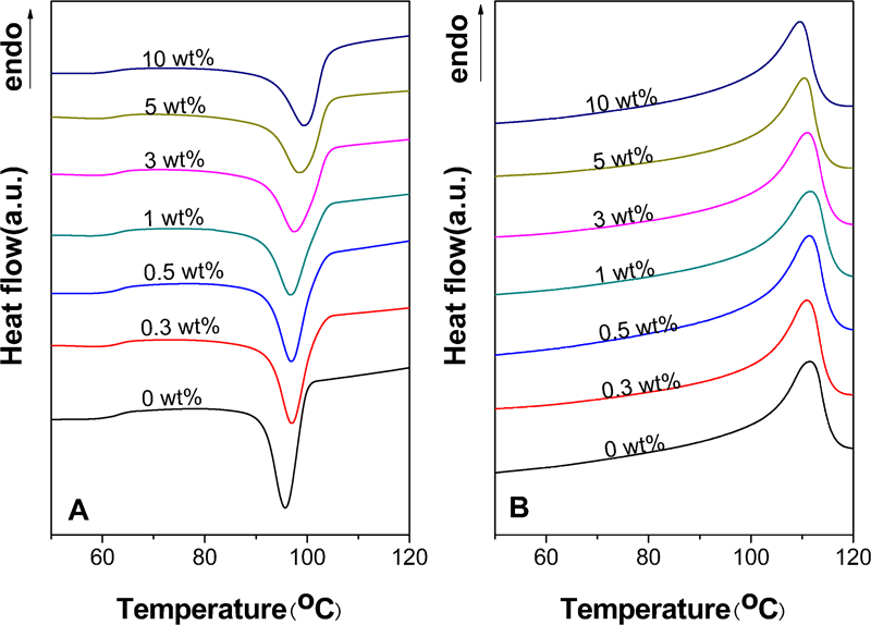
The crystallinity Xc (%) was calculated as14
XRD measurement
The samples were measured on X-ray diffractometer (XRD-6000; Shimadzu, Kyoto, Japan). The samples were recorded by diffractometer using Cu Kα radiation at 40 kV and 30 mA. The scan range 2θ was from 10 to 70°. The scan step was 0·02° with a rate of 4° min−1.
Electrical properties
Volume and surface resistivity
The high-insulation resistance meter (Zc-36; Shanghai Precision and Scientific Instrument Company Limited, Shanghai, China) was used to test the volume and surface resistivity of the samples at room temperature, following IEC 60093.
Dielectric constant and dielectric loss
The dielectric constant and dielectric loss of the samples were measured at room temperature by the impedance analyzer (4294A Precision Impedance Analyzer; Agilent, Palo Alto, CA, USA) at 5 MHz, following IEC 60250.
Mechanical properties
The sheets for mechanical testing were made into dumbbell shaped samples. Mechanical properties of samples were tested by universal tensile testing machine (MZ-2000C; Shenzhen Sans Testing Machine Inc., Shenzhen, China) according to ISO 527-1 at room temperature.
Rheological properties
The rheological properties were studied using melt flowrate (MFR) determination (XNR-400A; Changchun Second Machine Factory, Changchun, China), following ISO 1133 (190°C, 2·16 kg).
Results and discussion
SEM characterisation
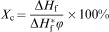
Figure 1 presents SEM images of the fracture surface of LPDE/POE/MWCNTs composites with different MWCNTs contents. Figure 1A shows the fracture surface of matrix, which was a comparison to surface morphology of composites. With the content less than 1 wt-%, MWCNTs have a better dispersion in composites. However, as the MWCNTs content increases, the MWCNTs aggregates appeared in the matrix, similar to the reports.16, 17 The aggregates were observed in Fig. 1E–G as well. It revealed that an upper limit exists for effective MWCNTs doping level. The MWCNTs contents of 3, 5 and 10 wt-% were so high beyond the critical point that some MWCNTs cannot be dispersed homogeneously in LDPE/POE matrix. The poor dispersion of MWCNTs in composites has a negative effect on physical properties of composites, such as mechanical properties and electrical properties. On the other hand, the pull-out MWCNTs were observed in SEM images of composites.
Images (SEM) of LDPE/POE/MWCNTs composites for different contents of MWCNTs
Crystallisation behaviour of composites
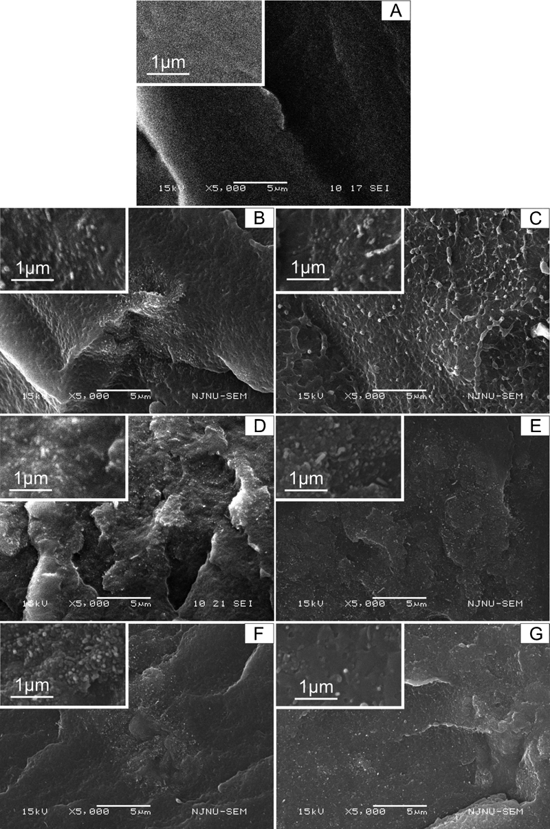
The DSC and XRD measurements have been performed to investigate the effect of incorporation of MWCNTs on the crystallisation behaviour of composite. The XRD patterns of MWCNTs and the LDPE/POE/MWCNTs composites with 0, 0·3, 0·5, 1, 3, 5 and 10 wt-% MWCNTs were shown in Fig. 2. For MWCNTs, the peak appeared at 2θ = 26·1° corresponding to the (002) reflection of the hexagonal crystal structure of graphite. As for the matrix, the (110) and (200) reflections were located at 2θ = 21·9 and 24·2° respectively. Since the POE was amorphous, the (110) and (200) peaks corresponded to the peaks of XRD patterns of LDPE. There were (110) and (200) peaks appear in the all XRD patterns of composites since LDPE is one of the matrix materials. As the MWCNTs was 10 wt-%, a visible MWCNT characteristic peak (002) emerged in the XRD patterns of composites. Meanwhile, in addition to them, no new peak appeared in the X-ray diffractogram of composites. It indicated that the incorporation of MWCNTs had no obvious effect on the crystal structure of LDPE/POE blends, and the structure of MWCNTs was also not influenced. The analogous result was observed in other CNTs/polymer composites.13, 21, 22
X-ray diffraction patterns for MWCNTs and LDPE/POE/MWCNT composites with different contents of MWCNTs
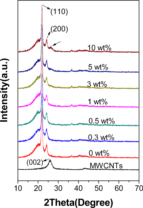
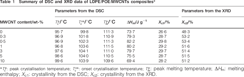
The crystallisation curves and melting curves of LDPE/POE blends and LDPE/POE/MWCNTs composites with different contents of MWCNTs were shown in Fig. 3A and B. For LDPE/POE/MWCNTs composites with different contents of MWCNTs, the peak crystallisation temperature
 , onset crystallisation temperature
 , peak melting temperature
 , melting enthalpy ΔHm and crystallinity Xc1 obtained from DSC and crystallinity Xc2 calculated from XRD were summarised in Table 1. Much research has been carried out on crystallisation behaviour of semicrystalline polymer added with CNTs. As tiny CNTs were dispersed uniformly in the polymer, it generally acts as the heterogeneous nucleating agent to accelerate the nucleation of polymer. Meanwhile, the strong nucleation effects lead to increase in crystallization temperature of polymer. Yang et al.18 reported that the addition of MWCNTs to LDPE increased the Tc and Xc of composite.
DSC A crystallisation and B melting curves of LDPE/POE/MWCNTs composites with different contents of MWCNTs
Summary of DSC and XRD data of LDPE/POE/MWCNTs composites*
 /°C
/°C /°C
/°C /°C
/°C*
 : peak crystallisation temperature;
 : onset crystallisation temperature;
 : peak melting temperature; ΔHm: melting enthalpy; Xc1: crystallinity from the DSC; Xc2: crystallinity from the XRD.
Table 1 shows that Xc1 increased by 3·2% when the content of MWCNTs was 0·5 wt-%. It indicated that the MWCNTs had a heterogeneous nucleation effect on LDPE/POE blends at low content. Nevertheless, with increasing content of MWCNTs, tiny decrease appeared in Xc1. It may be found that the MWCNT network formed in matrix hinders the diffusion of polymer chains during crystallisation, resulting in the decrease in Xc1. The analogous result has been reported by Yang et al.19 in poly(p-phenylene sulphide)/MWCNTs composites. Meanwhile, the Xc2 increases with 0·5 wt-% MWCNTs and decreases a few at 1 wt-%. With increasing content of MWCNTs, the Xc2 remain unchanged basically. The trend of Xc2 is consistent with that from DSC. For crystallinity determination, the difference between XRD and DSC measurement has been discussed by Lima et al.33 and Shi et al.34 Such difference can be explained by the normalisation factor used for crystallinity determination in DSC. Therefore, different measurement methods result in different values of Xc1 and Xc2 for same sample. Meanwhile, because of the strong nucleation effects,
 of composites increased by 3·9°C from 0 to 10 wt-% MWCNTs;
 increased by 4·3°C when the content was 3 wt-% compared with the matrix. Similar to Seo et al.'s research,20 there is no remarkable change in
 of composites with the addition of MWCNTs.
Electrical properties
The unique tube structure and π band, through which the electrons transfer, benefit electronical conductivity of MWCNTs. As a result, the MWCNTs were used to improve the electrical properties in many composites.11, 23, 24 Figure 4 shows the effect of the loading of MWCNTs on the volume and surface resistivity of LDPE/POE/MWCNTs composites. The volume resistivity has a slight change with the content of MWCNTs below 5 wt-% compared to the matrix and a sharp reduction with the loading of increasing MWCNTs. As the content of MWCNTs was 10 wt-%, the volume resistivity of composite reduced from 1·2×1012 to 6·2×107 Ω m, with five orders of magnitude lower than that of matrix. The MWCNTs of 1 wt-% or below has obscure impact on the surface resistivity of the composites, as demonstrated in Fig. 4. However, the surface resistivity decline from 1·3×1014 to 4·9×1010 Ω as the content of MWCNTs increased from 1 to 10 wt-%. The volume resistivity and surface resistivity of composites all decrease with the incorporation of MWCNTs. However, the volume resistivity and surface resistivity of composite are still at a high level with 10 wt-% MWCNTs, which may be due to the bad dispersion of MWCNTs.
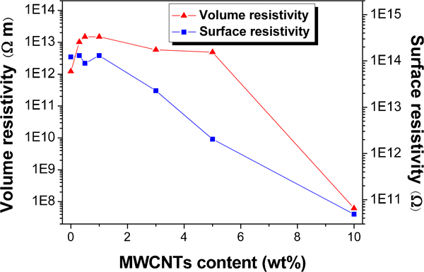
Volumes and surface resistivities of LDPE/POE/MWCNTs composites with different contents of MWCNTs
The notable falling volume and surface resistivity indicate a percolation threshold, as other CNTs/polymer composites20, 25, 26 shown. For volume resistivity, the percolation threshold was between 5 and 10 wt-%. And the percolation threshold of surface resistivity was between 1 and 3 wt-%. As the filler was continually added into the matrix, the MWCNT paths grow as well, and a MWCNT network forms in the matrix at last. The formation of MWCNT network remarkably boosts the electrical conductivity, which is the so called percolation threshold phenomenon.
Figure 5 shows the correlation between dielectric constant and loss of composites and MWCNT loading, measured at room temperature and 5 MHz for frequency. The dielectric constant and dielectric loss varied slightly when the contents of MWCNTs was below 5 and 3 wt-% respectively. With increasing content of MWCNTs, the dielectric constant and dielectric loss increased obviously. The dielectric constant for 10 wt-% MWCNTs composite increased from 3·5 for pure matrix to 9·0 and dielectric loss for 10 wt-% MWCNTs composite increased by 200 times compared with the controlled sample.
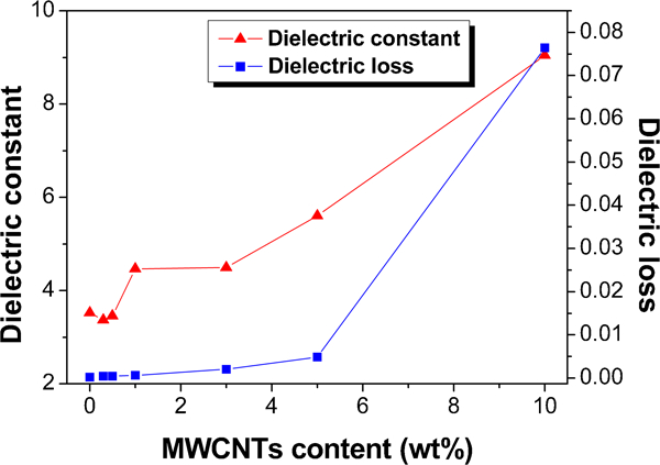
Dielectric constant and dielectric loss as function of MWCNT loading for LDPE/POE/MWCNTs composites with different contents of MWCNTs, measured at 5 MHz and room temperature
It is highly possible that with the addition of MWCNTs, the dipole polarity of composites in the interfacial region increased. Then, the enough polarisation of MWCNTs provides the larger dielectric constant and loss than those of the controlled sample. On the other hand, the MWCNTs were conductive and the matrix was dielectric. As the MWCNTs loading increased, the MWCNTs dispersed in matrix were percolated and contacted with each other. When the content of MWCNTs was in the neighbourhood of percolation threshold, the contact MWCNTs can form MWCNT–MWCNT nanocapacitors27 which resulted in the sharp increasing dielectric constant. Since the electrons in MWCNTs were lossy, dielectric loss of composites increased with increasing MWCNT loading.
Mechanical properties
The effect of content of MWCNTs on tensile strength and elongation at break was shown in Fig. 6. Compared with the controlled sample, the tensile strength of the composite with 0·5 wt-% MWCNTs had no appreciable change. The elongation at break increased slightly when the content of MWCNTs was 0·5 wt-%.
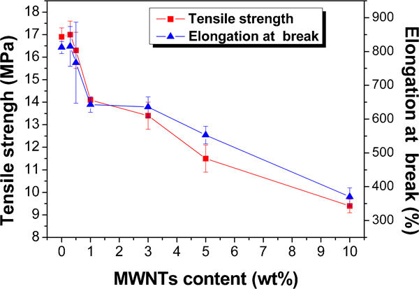
Tensile strengths and elongations at break of composites for different contents of MWCNTs
Nevertheless, both the tensile strength and elongation at break of composite decreased gradually, as the content of MWCNTs was above 0·5 wt-%. When the MWCNT loading reached 10 wt-%, tensile strength decreased from 17·1 to 9·4 MPa (a decrease of 45·1%), and the elongation at break of composite reduced from 730 to 370% (a decrease of 360%). The similar phenomenon was observed in other CNTs/polymer composites.28, 29 It is probable that the MWCNTs have a bad dispersion in matrix at a high loading and MWCNTs aggregates formed in matrix initiate the tiny cracks under stress. The crack was generally the reason for the decline of the strength and elongation at break of the composites. Another possible reason was that the interface bonding between matrix and MWCNTs was weak non-covalent bonding.30 The load relies on the fact that the composite was transferred to polymer and nanotubes by interfacial stress. Thus, the MWCNTs were pulled out under tensile loading, which was verified by SEM images above. On the other hand, the crystallinity of composite increased slightly with adding MWCNTs, which can make tensile strength increase. In comparison, the effect of the bad dispersion and weak interface bonding was dominant in mechanical properties of composites at high level contents of MWCNTs.
Rheological properties
MFR was a convenient method to analyse flow properties in the plastic processing industry. Besides the effects discussed above, the formation of MWCNTs network obstructed the chains motion of polymers as the melt flowrate demonstrated in Fig. 7. When the MWCNT loading was below 1 wt-%, the MFR value of composites decreased slightly. Nevertheless, when the MWCNT loading was 10 wt-%, the MFR value reduced from 1·0 to 0·2 g/10 min (a decrease of 77%) compared with LDPE/POE blends. The decline in the MFR value of MWCNT composites with increasing filler content was also reported in other research.31, 32
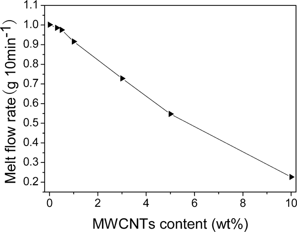
Effect of MWCNT content on melt flowrate of LDPE/POE/MWCNTs composites
The key point for the slowing flowrate is the interaction between the polymer chains of matrix materials and the filler.34 The low level content of filler has negligible impact on hindering the flow of polymer. However, as the MWCNT network forms, the long polymer chains are prone to entangle on the filler network, or to adsorb on the large surface of filler in the matrix. The movement of polymer chains, hence, apparently declines as the MFR diagram illustrated.
Conclusions
The effect of MWCNTs on morphology, electrical, mechanical and rheological properties as well as crystallisation behaviour of LDPE/POE/MWCNTs composites was studied. The SEM image indicated that the MWCNTs were dispersed uniformly in matrix with low content (<1 wt-%); meanwhile, MWCNTs aggregates appeared in the composites with high content. The DSC analysis shows that the crystallinity and crystallisation temperatures of composites all increased with incorporation of MWCNTs, which indicated that the MWCNTs had a nucleating effect on LDPE/POE. The XRD measurement reveals that the incorporation of MWCNTs had no obvious effect on the crystal structure of LDPE/POE blends. When the MWCNTs network formed in matrix to create conductive paths, the MWCNTs content reached up to the percolation thresholds, which resulted in the electrical resistivity of composites decreased obviously. The percolation threshold of volume resistivity was between 5 and 10 wt-% and the percolation threshold of surface resistivity was between 1 and 3 wt-%. The volume and surface resistivity of 10 wt-% MWCNTs composite decreased by five and four orders of magnitude in contrast with matrix respectively. The dielectric constant of composite increased up to 9·0 and the dielectric loss grew at 200 times than that of pure matrix with 10 wt-% MWCNTs content. The decrease in electrical resistivity and increase in dielectric constant of composite were favourable for some application, such as antistatic materials. The network of MWCNTs forming in matrix also resulted in the MFR value of composite with 10 wt-% content reduced by 77% compared to the matrix. The bad dispersion and weak interface bonding between matrix and MWCNTs resulted in decreased tensile strength and elongation at break of composites.