
Abstract
In this paper, the strength of non-crimp fabric Pi shaped adhesively bonded joints subjected to T-pull, T-shear, T-bending and T-tension loading conditions was evaluated experimentally. The bonded joints are based on the novel Pi shaped joining element, and they have been assembled using a new mixture of paste adhesives by means of the insertion squeeze flow bonding technique. Supplementary to experiments, a mesomechanical model, able to simulate the mechanical performance of the woven fabric structural parts, has been implemented in order to aid the evaluation of the experimental results and shed light in damage details that could be assessed by experimental methods. The study is focused on the integrity of both the Pi joining element and the bondline. The findings are very promising regarding the potential use of the joining element as a modular joint for the assembly of composite aerostructures.
Introduction
Conventional mechanical fastening for composite aerostructures, although optimised today, introduces a weight penalty due to the thickness increase in the assembled components near the bolts and the additional weight of the bolts.1 During the last two decades, extensive research has been in progress by experimental and numerical means aiming to optimise the design of composite bolted joints in a way that allows weight reduction.1 However, due to the complexity of composite materials, no significant improvement has been achieved, and the research community has alternatively directed interest to indirect solutions, such as cost effective reinforcement of existing mechanical fastening concepts and adhesive bonding.
For establishing adhesive bonding as a reliable joining method, the ability of the bonded joints to efficiently transfer load between assembled parts must be fully ensured. This pertains equally to the integrity of the joining element and the bondline. As the bonded joints are designed such that the load is transferred through shear, normal tensile loads arise in specific areas of the composite joining element. In the bonded joints between traditional composite laminates, such loads may lead to delamination in either the joining element or the assembled parts. Therefore, for this kind of application, new composite materials with enhanced through thickness properties must be employed. Such materials are the two- and three-dimensional woven fabrics and non-crimp fabric (NCF) composites. Assessment of the strength of these materials is still in progress. On the other hand, the integrity of the bondline depends on a variety of geometrical and material parameters. Geometry optimisation of the bonded joint is required to keep the maximum shear loads as low as possible.2 Epoxy adhesives are being replaced by high performance paste adhesives and mixtures of them.3 Beyond any doubt, the quality of the bondline plays an important role since imperfect bonding may cancel all the aforementioned improvements. 4 , 5
The work reported in the literature on composite joining profiles is limited and concentrated on T-joints. Mainly, the mechanical behaviours of transversely stitched T-joints 6 , 7 and T-joints for marine applications8–11 have been studied by employing both experiments and numerical analysis. In a recent paper, Chen et al.12 predicted the delamination of braided composite T-piece specimens using cohesive models. In none of these studies have T shaped profiles been used as joining elements to adhesively bond different parts. The first systematic research on the use of composite profiles as joining elements in adhesively bonded joints was conducted in the frame of a European research project evolved from 2006 to 2009.13 There, a material driven design concept for modular Pi, H, L and T shaped bonded joints, made of woven fabric material, was developed. The research pertained to the development of new manufacturing techniques for woven fabric profiles, new bonding techniques with controlled bonding quality as well as the optimisation of the profiles with regard to the integrity of the composite material and the ability of the bondline to transfer specific levels of load.
In the present paper, the research conducted on the assessment of the strength of Pi (
 ) shaped joints is described. Despite the similarities of the Pi element with the classical double lap shear (DLS) joint configuration, there are certain advantages that enhance the potentiality of the Pi based concept. For instance, in combination with other joining profiles, it introduces a modular joining concept that can be used to adhesively join several structural parts easily without modifying the configuration of the structure, as happens in the DLS joint.
This paper is divided into six main sections. Following this section, the problem is shortly defined in the section on ‘Geometries, materials and loading conditions’. In the section on ‘Experimental’, the experimental procedure is described. In the section on ‘Numerical model’, the authors provide a brief description of the numerical model used to support the experiments. Experimental results supported by numerical results for each load case are presented and discussed in the section on ‘Experimental results’. Finally, the authors conclude the article in the section on ‘Conclusions’.
Geometries, materials and loading conditions
Consider a Pi shaped joining element schematically described in Fig. 1a. The element is used to join a composite NCF skin with a composite insert, as shown in Fig. 1b. The ends of the Pi walls connected to the base have been rounded, and tapering was used in the opposite Pi walls in order to minimise shear stresses. It is desired to evaluate the strength of the joint. To this end, the joint is subjected to T-pull, T-shear, T-bending and T-tension loading conditions schematically defined in Fig. 2. Through this set of load cases, both the integrity of the NCF profile and the load carrying capability of the bondline will be assessed.
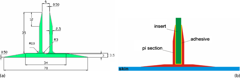
a schematic representation and dimensions (in mm) of Pi joining element and b schematic illustration of Pi joint
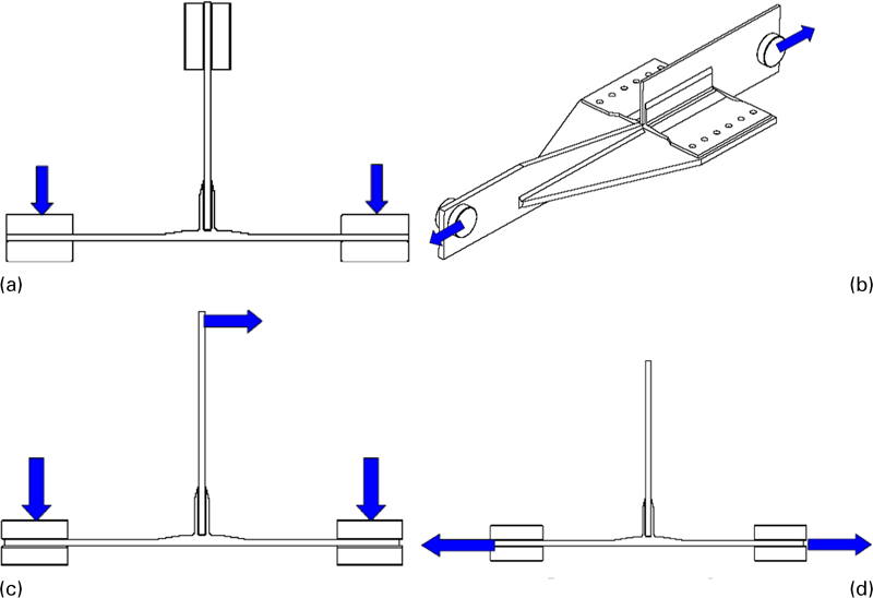
Schematic description of loading conditions for Pi shaped joint
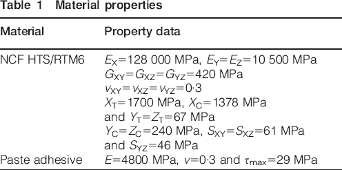
The Pi joining element, the skin and the insert are made of quasi-isotropic HTS/RTM6 NCF quad layers bound together with a thermoplastic veil by employing preforming and out-of-autoclave infusion methods.14 Bonding was carried out using the pressure free insertion squeeze flow process. 15 , 16 The adhesive used is a mix of the paste adhesives EA9395 and EA9396. The mean thickness of the bondline is 0·5 mm. The material properties of the HTS/RTM6 lamina and paste adhesive are listed in Table 1. The lay-up of the Pi element is described in Fig. 3.
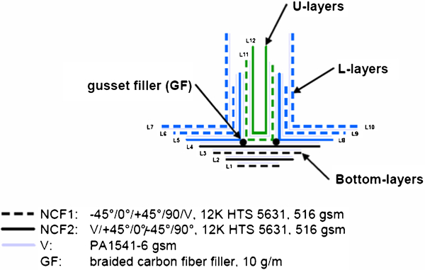
Lay-up of Pi
Material properties
Experimental
T-pull, T-shear and T-bending tests have been conducted using a Schenk machine with a load capacity of 250 kN, while T-tension tests have been conducted using an MTS 810 testing machine with a load capacity of 250 kN. The test loading speeds were 0·06 kN s−1 for the T-pull and T-shear load cases, 1 mm min−1 for the T-tension and 0·035 mm min−1 for the T-bending load case. At each load case, at least three specimens have been tested. At all the tests, the load–displacement curves have been recorded until the specimen's final failure. For all the load cases, except for the T-tension load case, special devices have been built in order to conduct the experiments. Photographs of the specimens mounted on the machines just before testing are displayed in Fig. 4.
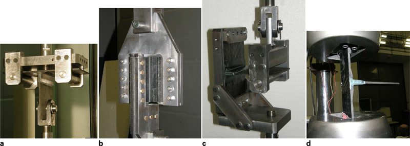
Specimens mounted on machine just before testing
Numerical model
Supplementary to experiments, a mesomechanical model has been implemented in order to aid the evaluation of the experimental results and shed light in damage details that cannot be assessed by experimental means. The model was developed by Tserpes and Labeas,17 and it is able to simulate the mechanical performance and predict the strength of textile structural parts. To date, it has been successfully applied to H shaped adhesively bonded18 and DLS joints.4 The model implements progressive damage modelling at two different scales: the microscale in order to numerically characterise the homogenised mechanical behaviour of the NCF material and the macroscale in order to predict the strength of the structural part. The first model component concerning the NCF HTS/RTM6 material has been described in detail in Ref. 5; thus, it will not be repeated herein. The only difference in the model between the previous applications and the current one lies in the finite element model of the structural part, which is illustrated in Fig. 5. In the model, all the parts have been represented using the ANSYS SOLID185 element.19 Owing to the large differences in the boundary conditions of the load cases, at each load case, the finite element model was modified accordingly. Wherever allowed from the geometry and boundary conditions, symmetry was used, and only one-half or one-fourth of the model was solved in order to reduce the required computational effort. The model is able to simulate the initiation and progression of different failure modes in the NCF material (Pi and skin) as well as debonding due to fracture or shearing of the adhesive.
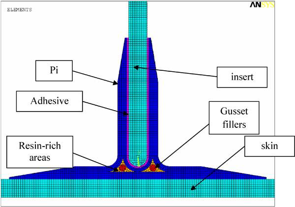
Finite element mesh (front view) of Pi shaped bonded joint with indication of assembled parts
Results
T-pull
The scope behind T-pull tests was to check the performance of the Pi walls in transferring tensile loading as well as the ability of the Pi base to resist out-of-plane normal stresses, which tend to delaminate the stitched layers. Another interesting point regarding the effectiveness of the joint is whether the bondline or the joining element will fail due to shearing before Pi. In order to avoid for the axial pullout load applied to the insert to be transferred through bending of the skin and Pi base, the constrains in the skin were applied through steady rollers (see Fig. 4a), which allowed for the skin to roll under, thus reducing bending.
All three specimens tested for T-pull failed due to the interlaminar fracture (delamination) that initiated at the Pi base/skin interface and propagated parallel to skin (Fig. 6). The interlaminar fracture was due to the large normal stresses maximised at the edge of the Pi. Figure 7 shows the distribution of the normal stress computed by the model. The fracture initiated at the Pi edge and propagated inwards, as revealed by the transfer of the stress maximisation point. The final failure of the specimens was due to either a combination of delamination and bending of the skin (Fig. 8a) or a complete separation of the Pi from the skin without any significant damage in the skin (Fig. 8b). The final failure mechanism influences significantly the total amount of load sustained by the joint. In Fig. 9, the maximum loads measured for the three specimens tested are displayed. An average value of 6·81 kN was obtained. Complete delamination of Pi from the skin leads to very small maximum loads (5·5 kN for specimen C101). On the contrary, in specimen C102, where complete delamination was prohibited and the load has been mainly transferred through bending of the skin, the maximum measured load was 12·2 kN, which is more than twice the failure load of C101.
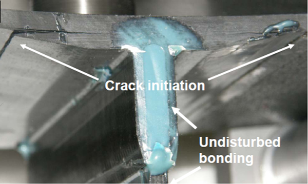
Initiation of interlaminar fracture in Pi shaped joint due to T-pull loading
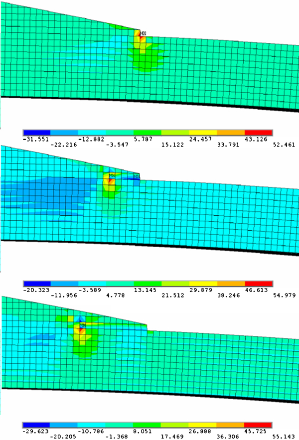
Computed contour of normal stress (in MPa) at joint subjected to T-pull as function of applied load: focus on edge of Pi
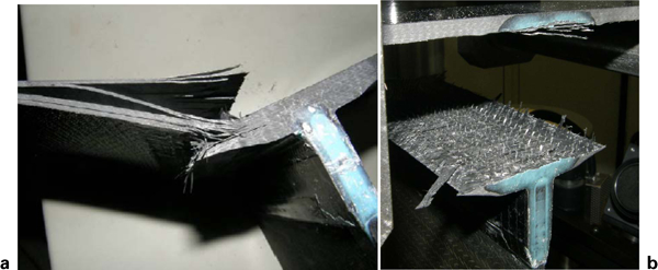
T-pull specimen failed due to a bending of skin and b detachment of Pi from skin due to delamination
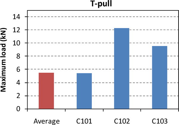
Maximum loads measured in T-pull tests
A very important finding in the T-pull tests is the total absence of debonding in all the specimens tested; this can be revealed by careful examination of the bondline in Figure 6 Figs. 6 and 8. This is, of course, an indication about the load carrying capability of the bondline. However, as the boundary conditions did not lead to pure pullout loading of the insert (this could be achieved by fully constraining the Pi base), the maximum loads measured in the T-pull experiments cannot be directly associated to the shear strength of the bondline. In any case, it can be concluded that the shear strength of the bondline appears to be larger than the interlaminar strength of the NCF layers, which brings out the need for further out-of-plane reinforcement of the joining profiles.
T-shear
The T-shear tests aimed to assess the shear performance of the Pi walls and the bondline. All the specimens loaded in T-shear failed due to debonding, which caused the insert to be pulled out from the Pi (Fig. 10a and b). Debonding resulted from the interaction of a set of secondary failure mechanisms, as follows:
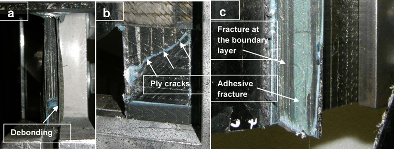
Different views of specimen loaded in T-shear with indication of different failure mechanisms occurred
extensive ply cracks at the layers attached to the bondline (boundary layers) in the direction perpendicular to loading (Fig. 10b)
fracture at the boundary layers due to large shear stresses (Fig. 10c); in some cases, the boundary layer was detached from the Pi together with the insert
adhesive fracture (no cohesive fracture was observed) (Fig. 10c).
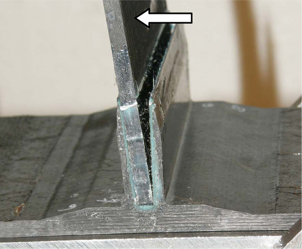
The predicted evolution of debonding is illustrated in Fig. 11. As can be seen, debonding initiated at Pi edge and propagated inwards as the insert was being pulled out from the Pi. The shape of the debonded area is in agreement with the respective pattern observed in the experiments (Fig. 10b). The maximum loads measured in the T-shear tests are summarised in Fig. 11. An average value of 72 kN with a small scatter was obtained.
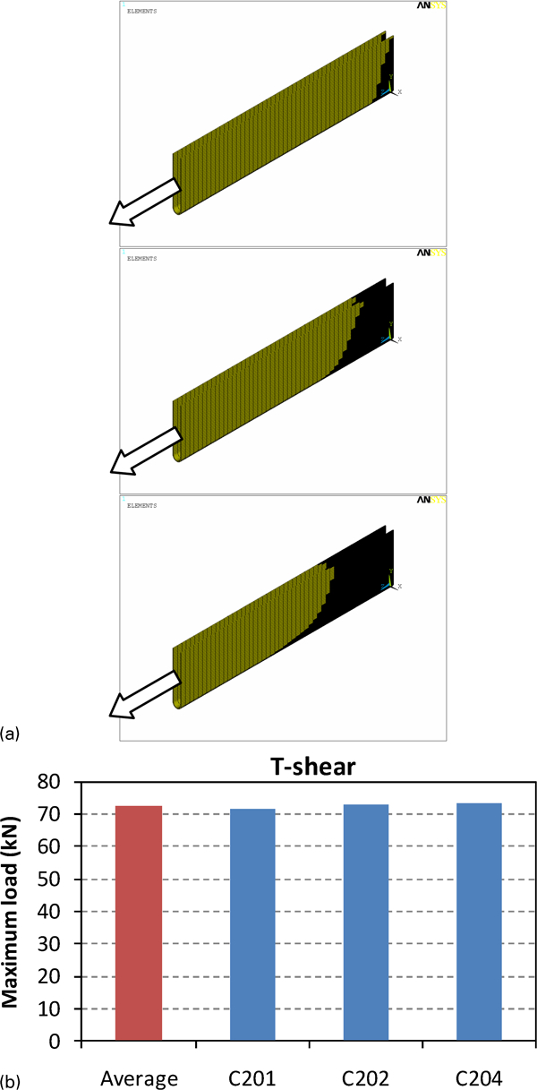
a predicted evolution of debonding in specimen loaded in T-shear (only adhesive is shown) (arrow indicates loading direction) and b maximum loads measured in T-shear tests
It is well known that for the design of a bonded joint subjected to shear loading conditions to be successful, the desired failure mode is cohesive fracture (the crack propagates inside the bulk polymer, which constituents the adhesive). As all the specimens tested in the frame of this study in T-shear failed due to adhesive fracture, several aspects arise for the design of the joints. A very important parameter is the quality of the bondline measured in terms of void content in the bondline. Indeed, in Refs. 4 and 5, it has been shown that, in some cases, a significant amount of voids may be present in the bondline as a result of the adhesive's difficulty to climb from the Pi slot, where it is initially accumulated, to the gap between the Pi walls and the insert. The adhesive's viscosity and surface treatment of the adherents are two parameters that may influence the quality of the bondline. A numerical study by Tserpes et al.5 has shown that if the imperfectly bonded areas are located close to the high stress concentration areas, then their presence may influence the strength of the bonded joint and the failure mechanism. Based on the above, it becomes likely that the failure mechanism of adhesive fracture is partly attributed to imperfect bonding.
T-bending
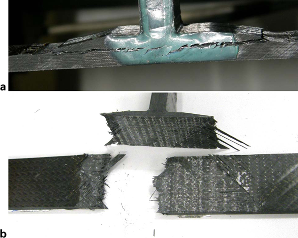
The T-bending tests aimed to assess the bending performance of the Pi walls and at the same time the tensile and compressive performance of the bondline. For this load case, the failure mechanism was debonding of the insert from the Pi occurring at the stretched part of the joint, as can be seen in Fig. 12, due to the large tensile normal stresses. The computed distribution of normal stress at the adhesive is illustrated in Fig. 13 for different load steps. The normal stress is maximised at the top of the joint. Debonding initiated at this point and propagated downwards, as revealed in Fig. 13, by the movement of the point of maximum stress. Actually, the area above the line of stress maximisation has been debonded. Contrary to bondline, both the Pi walls and the Pi base have sustained bending loading without any visible sign of damage. The maximum loads measured in the T-bending experiments are displayed in Fig. 14. An average maximum load of 2·68 kN was obtained.
Failure due to debonding of specimen loaded in T-bending
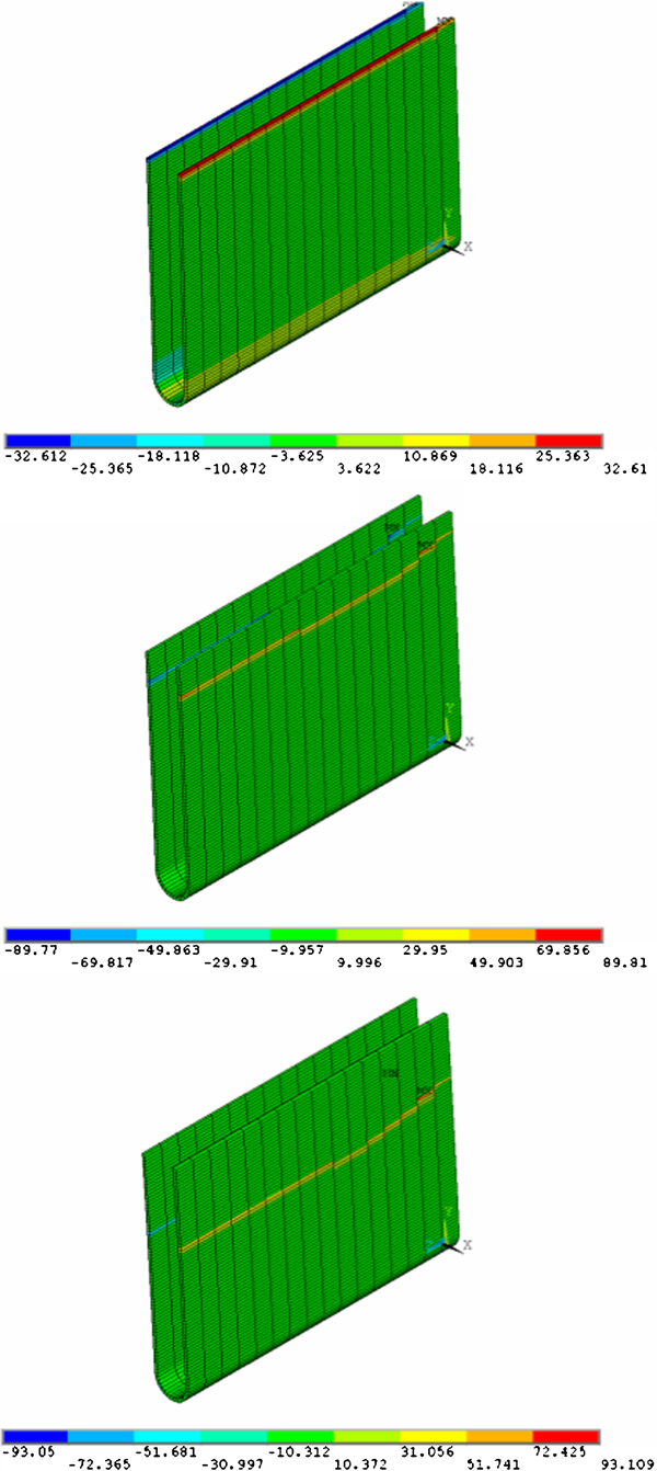
Computed distribution of normal stress at adhesive (in MPa) being responsible for debonding (only adhesive is displayed)
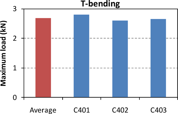
Maximum loads measured in T-bending tests
T-tension
T-tension aimed to check the response of the Pi/skin interface under axial tensile loading. In this case, no direct loading was applied to the bondline; thus, it was expected to remain intact. Indeed, all the specimens tested in T-tension failed through the following sequence:
initiation of a crack at one edge or both edges of the Pi due to the large normal and longitudinal stresses caused by the geometrical discontinuity and the mismatch in the longitudinal stiffness between the Pi and the skin
propagation of the crack(s) inwards until the complete separation of the Pi from the skin
fracture of the skin due to longitudinal stresses.
Figure 15a illustrates a specimen tested in T-tension at the stage where crack has propagated from the edges just before causing separation of the Pi from the skin. The final failure condition of the specimen is illustrated in Fig. 15b. The maximum loads measured in the T-tension experiments are displayed in Fig. 16. An average value of 106·67 kN was obtained.
a cracked specimen loaded in T-tension and b final failure state of specimen loaded in T-tension: Pi is detached from skin, and skin is fractured
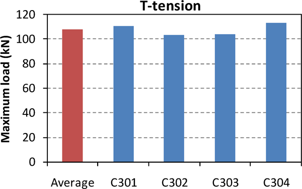
Maximum loads measured in T-tension tests
Conclusions
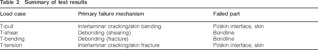
In this paper, the strength of the NCF Pi shaped adhesively bonded joints under the loading conditions of T-pull, T-shear, T-bending and T-tension has been evaluated experimentally with the aid of numerical modelling. Through these load cases, the integrity of both the NCF joining element and the bondline was tested. The findings of the study are summarised in Table 2. From Table 2 and the comments made in the previous sections of the paper, it is concluded that the Pi walls of the NCF joining element are very effective in carrying tensile, bending and shear loads developed in the T-pull, T-shear and T-bending load cases respectively. In these cases, the joint failed either due to interlaminar cracking of the Pi/skin interface, accompanied by skin bending, or debonding. As the interlaminar cracking of the Pi/skin interface is also the failure mechanism in the T-tension load case, it is concluded that there is a strong need for enhancing the Pi base and Pi/skin interface in the through thickness direction by elements, which will be able to effectively carry through thickness stresses, thus prohibiting delamination. Towards this direction, several solutions have been already proposed in Ref. 13. Among them are the use of polymeric staples and pins. The effectiveness of these solutions will be the subject of future investigation in this area. In cases where the joint failed due to debonding, imperfect bonding has been found to play an important role. 4 , 5 This is strongly supported by the observed failure mechanism of adhesive fracture instead of cohesive fracture, which is the desirable mechanism for a successfully designed bonded joint. Thus, another step that must be taken towards the improvement of the Pi shaped bonded joints tested in this work is the improvement of bonding quality.
Summary of test results
Footnotes
Acknowledgements
The current research was conducted within the frame of the EU Project ‘MOJO’ (Modular Joints for Composite Aircraft Components). The financial support provided by the European Commission under contract no. 030871 (FP6) is gratefully acknowledged. The authors would also like to thank Premium Aerotec GmbH and Eurocopter Deutschland GmbH for manufacturing and assembling the specimens.
This paper is part of a special issue on Durability of composite systems