
Abstract
Fatigue tests were conducted on two kinds of vulcanised natural rubber with different formulas under uniaxial and multiaxial loading. The results reveal that interfacial adhesion of material A is better, and compared with material B, fatigue life of material A is longer. Under the same engineering strain amplitude, lower fatigue life under tension-torsion non-proportional loading is due to the increase in total hysteresis energy in the torsional direction. Scanning electron microscopy analysis showed that fatigue failure is related to ligaments breakage for material B, while cavitation induced by the decohesion between zinc oxides and rubber matrix is the main cause of the fatigue damage for material A.
Introduction
Rubbers are extensively used in many applications because of their large reversible elastic deformation, excellent damping and energy absorption characteristics. Typical applications include engine mounts and tires for automobiles, vibration isolators, seals, hoses, belts, structural bearings, etc. Since these applications impose large static and time related strains, durability and mechanical properties are often the primary consideration. It is pivotally important to investigate the fatigue characteristics and mechanism of rubber.
The study of rubber fatigue can be traced back to Cadwell's1 investigation on natural rubber NR in the 1940s. Afterwards, Lee,2 Sun3 and Ellul4 focused on the influence of loading valley values, loading modes and loading rates on tire rubber fatigue performance through a lot of experiments. However, all the works were mainly confined to uniaxial fatigue. Until the beginning of this century, multiaxial fatigue of rubber did not receive attention.5–19
Studies mentioned above were all based on phenomenological and macroscopic theories. However, phenomenological methods could not fully predict the crack propagation process in rubber.20–22 Therefore, further investigation to the fatigue failure mechanism of rubber and its relation with macromechanical characteristics is crucially important to anti-fatigue design and fatigue life predicted model. There have been several studies on uniaxial fatigue failure mechanism using scanning electron microscope (SEM). Eldred23 first used SEM to investigate rubber fatigue fracture. Lake and Yeoh24 described the cutting resistance of rubber where there was little or no effect of friction. Stevenson and Thomas25 observed the bursting of a natural rubber balloon. Another study of Stevenson26 was about fracture mechanics study of the rubber fatigue in compression. He found that fatigue crack growth occurred in compression at an approximately constant rate, and tearing energy was restricted to the outer regions of the test pieces with high local shear strains. Mathew et al.27 found that unvulcanised rubber presented plastic failure and carbon black filled mixes showed brittle failure which changed to quasi-ductility with the addition of antioxidant. Choudhury and Bhowmick28 and Fukahori29 observed the structure of fatigue fracture section using SEM. Lately, Hainsworth30 investigated fatigue crack initiation and propagation in silicone rubber and carbon black filled rubber with an environmental SEM, and found that the crack growth processes were non-linear and cracks were particularly found to initiate at edges and flaws in the sample. Le Cam et al.31 observed microscopic phenomena involved in the growth of the crack with SEM. It revealed that the cavitations induced by decohesion between zinc oxides and rubber matrix were major fatigue damages. Beurrot et al.32 proposed the peculiar morphology of the crack tip and mechanism of crack propagation in NR was due to strain induced crystallisation. However, only Mars and Fatemi33 observed the surface morphology of fatigue failure specimen under multiaxial cyclic loading. Until now there are a few studies on microscopic mechanism of multiaxial fatigue of rubber. This study will focus on multiaxial fatigue mechanism of rubber materials.
Experimental
Materials and specimens
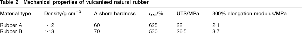
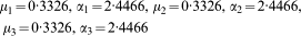
The materials studied are two kinds of vulcanised natural rubber with different formulas, which include natural rubber, charcoal, zinc oxide, stearic acid, antioxidant and accelerant, etc. The formulations are shown in Table 1. The cure condition is 30 min at 142°C. Their basic mechanical properties are listed in Table 2. The specimen geometry is shown in Fig. 1. The specimen is designed with the purpose of carrying out multiaxial fatigue tests so that the gauge length is short to avoid torsional buckling. Because of non-uniformity deformation of the specimen, the gauge length of the specimen cannot be taken directly as the grip-to-grip distance. Instead, an effective material element gauge length is estimated via comparison of the experiment and predicted axial load–displacement relationships by finite element analysis (FEA), which is known as inverse method.8 Therefore, a three-dimensional (3D) finite element analysis model is built with the software of ANSYS. The element used in FEA is solid182 U-P element. An incompressible, Ogden34 hyperelastic constitutive model is used in the analysis. It is expressed as follows

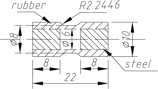
Dimensions of specimen (units: mm)
Experimental compound formulation used in this study
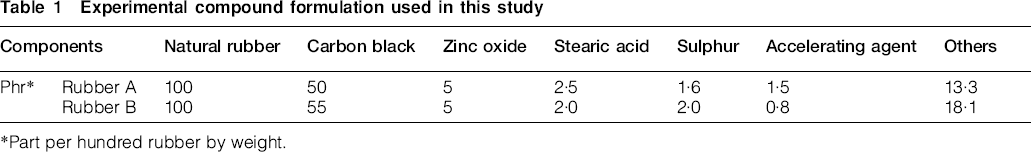
Part per hundred rubber by weight.
Mechanical properties of vulcanised natural rubber
Material A
Material B
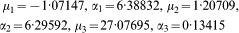
Comparison of test results and FEA results for two kinds of materials
Fatigue loading conditions
All the tests were conducted on a self-built mini type tension–torsion material testing apparatus which provides strain or stress control mode and controllable testing environmental temperature. The capacity of the testing apparatus was axial force of 100 N and torque of 1 Nm. Resolution of displacement was 1 μm and resolution of rotation was 0·004 degree, which met the demand of tests. The load was measured by a load cell. The displacement and rotation angle were measured by an optics encoder. The data were collected by an automatic data acquisition system. All the tests employed triangle wave and were conducted at room temperature.
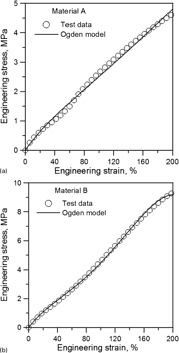
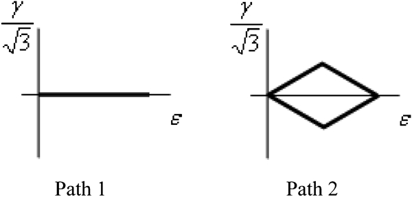
Figure 3 shows the loading paths adopted in rubber fatigue tests, which are uniaxial tension and rhombus loading path. A rapid loading drop knee point is defined as fatigue failure, normally about 30% loading drop for material A and 20% loading drop for material B, which usually causes a visible crack about 1 mm in size on the specimen. Fatigue test conditions and results for rubber material are listed in Table 3. The strain is engineering strain. Specimen 1-A means path 1 for material A, and the rest may be deduced by analogy.
Proportional and non-proportional loading paths
Fatigue test results
Observation of scanning electron microscopy
The failure section of vulcanised natural rubber was cut down from specimens. An XL30E SEM was used to take photographs for the failure sections. Energy spectrum analysis was also conducted.
Results and discussion
Fatigue property analysis
According to Table 3, under the same engineering strain amplitude, the fatigue life under non-proportional loading is much lower than uniaxial loading. On the one hand, this is because under non-proportional loading, the maximum shear stress plane rotates continuously leading to faster fatigue damage accumulation. This makes the van der Waals bond between the charcoal particles break much greatly. Thus, stress descends more rapidly due to the damage of rubber molecule chains. On the other hand, under the same condition, multiaxial case is more complicated loading path, leading to the increase in potential energy in multidirections.
At the same strain amplitude, the cyclic stable axial and shear stress–strain curves are shown in Fig. 4 for material A and material B under uniaxial and multiaxial loading. It can be seen from Fig. 4a that hysteresis loops of axial stress–strain are almost the same under uniaxial and multiaxial loading for the same material. However, the existence of the shear stress–strain hysteresis energy in Fig. 4b for multiaxial loading will induce more fatigue damage than that of uniaxial fatigue. Thus, the fatigue life under non-proportional loading is relatively short in Table 3. It also shows that the axial and shear stress response of material B is much higher than material A, so fatigue life of material B decreases due to easier chemical bonds breaking under higher stress.
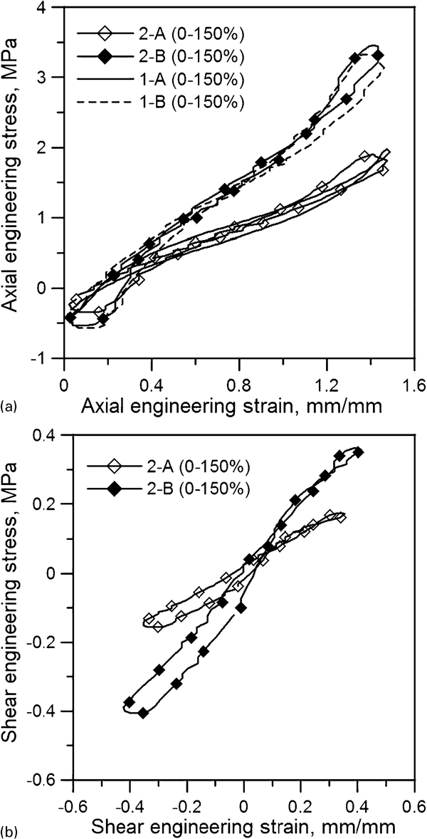
Stress–strain diagram for two rubbers under same strain amplitude
The stress amplitude drop curves with cycles under uniaxial and multiaxial loading for the two materials are shown in Figure 5 Figs. 5 and 6 respectively. Here, the stress is engineering stress. It can be seen from the figures that under either uniaxial or multiaxial loading, the dynamic fatigue process of rubber can be divided into three stages. The first stage is the initial part of test with a stress softening phenomenon. This significant initial decrease in material stiffness is believed to be related to the irreversible breakage of various types of bonds in the elastomer network.9 Then in the second stage, in half-logarithm coordinates, the load drop rate of material keeps a constant value, and stress changes slowly. Microcracks generate inside the material or on the surface, which results in macrocracks with a stable extending stage of cracks. In the third stage, cracks grow rapidly until failure occurs with an instable extending stage of cracks. A knee point is observed between the second and third stage. The stress drop rule in the torsional direction is similar with the uniaxial case, which can be divided into three stages.
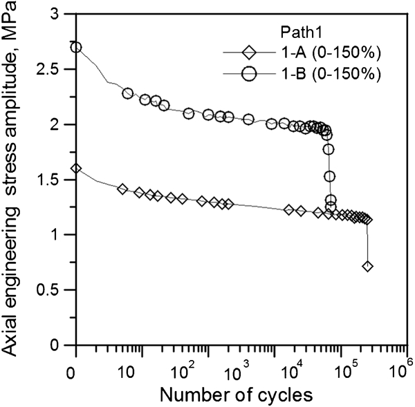
Stress amplitude evolutions with cycles for two kinds of materials under uniaxial loading
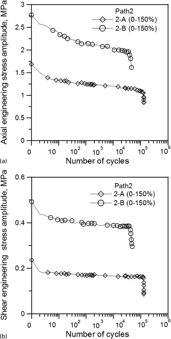
Stress amplitude evolutions with cycles for two kinds of materials under rhombic loading path
It can be seen from Figure 5 Figs. 5 and 6 that under either uniaxial or multiaxial loading, with the same strain value, the stress response of material A is much lower than that of material B, while the life of material A is much longer than that of material B. According to the viewpoint of molecule, dynamic fatigue failure is due to the break of chemical bond. During the cyclic strain load, stress concentrates on the weaker bonds continuously. When the stresses arrive the strength of bond, the bond breaks and microcracks occur. Hence, in the stress concentration point, the molecule chain in the tip of the cracks will elongate with viscoelasticity until breakage. Therefore, the fatigue life of material A is much longer than that of material B.
Micrography study of failure surface
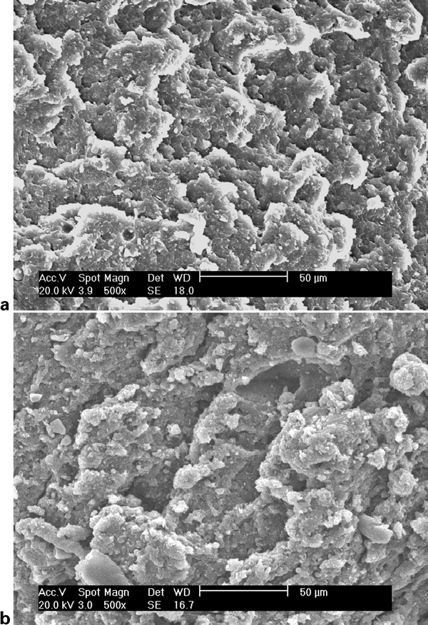
Based on the research of carbon black filled natural rubber, Le Cam et al.31 pointed out that the cavitation induced by the decohesion between zinc oxides and rubber matrix was the major fatigue damage. In the research of natural rubber, Saintier et al.18 reported that two main mechanisms of crack initiation were found to be independent of the type of loading (i.e. uniaxial or multiaxial) but depending on the nature of the inclusion: decohesion and cavitation. Hainsworth30 pointed out that the cracks were found to initiate at the defects associated with sample geometry and thickness. In this study, energy dispersive spectroscopy analysis revealed that a large variety of inclusions are present in natural rubber. The most often encountered are ZnO, SiO2 and CaCO3, which must be added into the material during the production of materials. High resolution SEM analysis showed that the agglomerates (generated from ZnO/carbon black) resulted from inhomogeneous mixing during material processing, as shown in Fig. 7. In Fig. 7a, plenty of small particles and cavitations are found. It can be seen that agglomerates do not show a clear interface with the rubber matrix. Flat and smooth fracture surface shows brittle failure, which is in accordance with those observed, that is, when the crack on the surface occurs with 1 mm length, the specimen breaks suddenly during cyclic loading. Figure 7b shows a scale-like fracture surface, which may be due to the incremental crack propagation during fatigue. The blunt ends and dimples on the surface are caused by the ductile failure of matrix. It can be observed from Fig. 7b that a number of small ligaments occur in the interface.
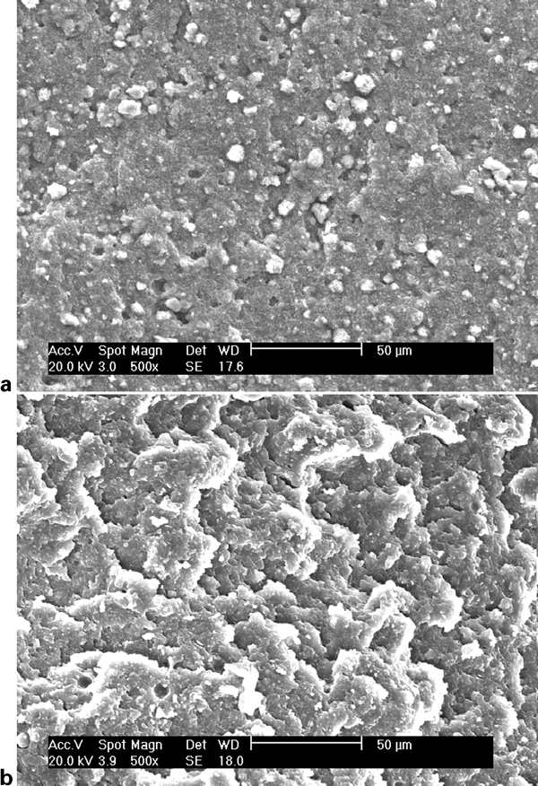
Fatigue fractured surface under uniaxial loading ×500
It can be observed in Fig. 7 that the interfacial adhesion between filler and rubber matrix in rubber A is better than that in rubber B, which is helpful to reduce the amount of heat produced during deformation and the chain breaking and consequently further increases the fatigue life. In addition, better interfacial adhesion also results in better dispersion and improves wettability of filler particles in the rubber matrix, which reduces the formation of stress concentration and then enhances the fatigue life.35 As more and more filler is added into the rubber matrix, it can be anticipated that filler particles and agglomerates will not be dispersed and wetted efficiently by the rubber matrix.35 These inherent defects can act as stress concentration points and shorten the fatigue life of the vulcanisates.36 Again, it can be seen in Table 1 that material B contains more filler than material A. Therefore, material B is easier to be failure and exhibits lower fatigue life than material A (see Table 3).
For the sake of comparison on the effect of multiaxial loading on fatigue life, the fatigue failure surfaces were examined for material A and material B under uniaxial and multiaxial loading at the same strain amplitude. Figure 8 Figures 8 and 9 show the fatigue failure surfaces of material B and material A under uniaxial and multiaxial non-proportional loading. For the same material, fatigue life under multiaxial loading is much lower than that under uniaxial loading (see Table 3). As observed previously, fatigue crack growth is driven by ligaments breakage.30–32 It can be observed from fracture surface in Fig. 8 that the pattern of ligaments is different between specimen 1-B and specimen 2-B. Fracture surface for specimen 1-B shows scale-like fracture surface, and the shape and size of ligaments are relatively sharp and small compared with that of specimen 2-B. However, fracture surface for specimen 2-B shows a rougher surface that corresponds with broken ligaments shrunk. Therefore, under path 2 loading for filler NR, ligaments breakage is easier due to the existence of multiaxial loading. Brittle failure occurs on the failure surface of both specimens 1-A and 2-A. However, comparing with the failure surface of specimen 1-A, there are more cavities formed by escaped more agglomerates for specimen 2-A as shown in Fig. 9. Therefore, the decreased fatigue life of natural rubber under path 2 loading can be explained as it is poor interfacial adhesion between the filler and the matrix with multiaxial loading. Therefore, under non-proportional loading, the chemical bond of the material breaks faster and then the fatigue damage develops faster.
Fatigue fracture surface of material B×500
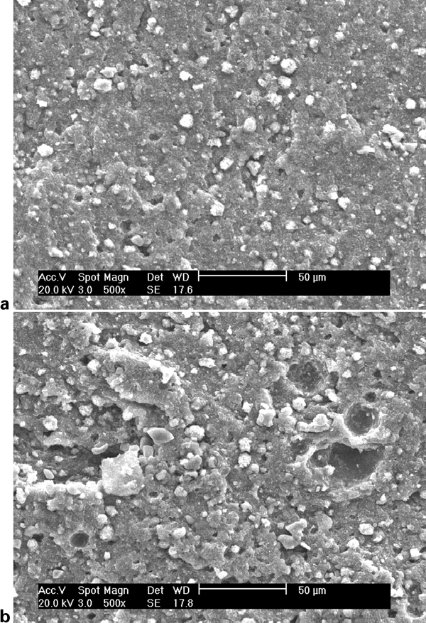
Fatigue fracture surface of material A ×500
Conclusions
Through the investigation and discussion of two kinds of vulcanised natural rubber with different formulas, the following conclusions can be drawn.
Under the same equivalent strain amplitude, the fatigue life is shorter in tension-torsion non-proportional loading due to the increase in hysteresis energy in the torsional direction than that in uniaxial loading.
With the same strain value, the stress response of material B is much higher than that of material A, and the fatigue life is much shorter. The observations of SEM for fatigue failure surface reveal that interfacial adhesion of material A is better than that of material B. Therefore, fatigue life of material A is longer.
Through the observation of SEM for fatigue failure surface, it is found that material A shows flat and smooth fracture surface, which is brittle failure. However, material B presents scale-like fracture surface, which is ductile failure. Shape and size of ligaments of specimen 2-B are relatively blunt and big compared with those of specimen 1-B. Ligaments breakage is easier due to the existence of multiaxial loading. Comparing with the break surface of specimen 1-A, there are more cavities formed as more agglomerates escape for specimen 2-A, which is poor interfacial adhesion between the filler and the matrix under multiaxial loading.
It can be found from the analysis that fatigue failure is related to ligaments breakage for material B, but cavitation induced by the decohesion between zinc oxides and rubber matrix is the reason of the fatigue damage for material A. It may be due to the different strain induced crystallisation degree. It would be interesting to investigate the failure mechanism due to strain induced crystallisation degree on filler NR material in the future.
Footnotes
Acknowledgements
The authors gratefully acknowledge financial support from the National Natural Science Foundation of China (grant no. 11062006) and Natural Science Foundation of Inner Mongolia Antonomous Region of China (grant no. 2009BS0806).