
Abstract
Interrupted tensile tests were performed on different notch profile polyoxymethylene specimens at 160°C primarily in order to provide sample material for morphological and structural examinations. Scanning electron microscopy and small angle X-ray scattering were employed to examine the contribution of microvoids and other forms of damage to the large scale tensile deformation behaviour. It was established that the nucleation of spherical microvoids occurs during tensile deformation in the pre-yielding region. It was also concluded that voiding is well established by the yield point, while the formation of new microvoids is a continuous process during subsequent deformation. The interrupted tests clearly demonstrated the different stages in the formation, growth and coalescence of voids to form a continuous fracture path leading to fibrillation of the material and ultimately to fracture. Simple finite element models were used to predict the evolution of stress triaxiality with increasing deformation in the notched specimens.
Introduction
Polymers are widely used in numerous engineering applications as a direct replacement of conventional materials, such as metals and ceramics. Their characteristic properties and low production cost make them highly desirable in the automotive and aerospace industries. The extensive use of polymeric materials is the result of considerable knowledge of their structure, morphology and deformation behaviour that was obtained during the twentieth century. In addition, solid state molecular orientation can provide significant enhancement of the mechanical and physical properties of isotropic polymers, making them one of the most versatile engineering materials.1–3
The degree of property improvement during molecular orientation strongly depends upon the initial morphology of the material and the sensitivity of its mechanical response to the precise applied deformation conditions. These include the applied strain, strain rate, temperature, hydrostatic pressure and adopted size and shape of the specimen.4, 5 Therefore, the measurement of reliable data for polymers under different loading conditions and over a wide range of strain rates is still required.6 The resulting data can be used in the numerical modelling of solid state forming processes in order to predict the polymer response while optimising the thermoforming conditions.7
The uniaxial tension and compression tests are the two most significant mechanical tests employed in the characterisation of the plastic deformation behaviour of semicrystalline polymers. Tensile deformation of polymers results in internal cavitation caused by microvoids that are formed in the interlamellar spaces and the amorphous regions of the material.8 Subsequently, the applied tensile stresses enable the growth and coalescence of voids, leading to material fibrillation and ultimately fracture of the deformed specimen. On the other hand, the cavitation effect is minimised during compressive deformation due to the hydrostatic compressive stresses that suppress void formation and growth.9
The present study investigates the morphological and structural developments of polyoxymethylene (POM) under uniaxial tension. Polyoxymethylene is one of the major engineering polymers and is used in highly demanding applications, such as mechanical, electrical and automotive engineering, conveyor technology and construction of household appliances. Polyoxymethylene is characterised by superior mechanical behaviour, low creep, dimensional stability, low coefficient of friction against steel and the ability to maintain mechanical properties at elevated temperatures.
The aim of this paper is to present a comprehensive study of the effect of voiding on the large scale deformation and fracture behaviour of POM at elevated temperatures under uniaxial tension. The experimental studies were carried out at elevated temperatures typical of those used in solid state molecular orientation processes.4, 7 In addition, material characterisation through structural and morphological studies was performed to examine the effect of internal cavitation in the material at different levels of deformation. Furthermore, the tensile tests were simulated by isothermal finite element models developed using a commercial finite element code (ABAQUS) and a simplified material constitutive relation for POM.
Experimental
Materials and test specimens
The material used in this study was POM Delrin 150 NC010 supplied in rods of 25 mm diameter by DuPont (UK) Limited, Hertfordshire. This diameter was adequate to provide the desired cylindrical tensile specimen profiles. The density and number average molecular weight of this POM grade were 1·423 g cm−3 and 66 000 respectively. Delrin 150 NC010 is a nucleated grade of POM, in which the formation of a large number of small spherulites is expected during the extrusion process. The addition of nucleating agents leading to smaller spherulites reduces the likelihood of pre-existing voids in the material.
The thermal characterisation of the isotropic Delrin 150 NC010 samples was conducted on a PerkinElmer DSC 7 analyser. The crystalline melting temperature was determined at a scanning rate of 10°C min−1 under nitrogen atmosphere using an average sample weight of 5 mg. The temperature and enthalpy calibration of the system was carried out using indium, while all the results reported are an average from five scans. It was found that the isotropic Delrin 150 NC010 had a melting temperature of 180·5±0·5°C. The degree of crystallinity determined from these DSC results at the core of the extruded rod was 61±1% when assuming that the POM crystal heat of fusion is 317·93 J g−1.10
A wide range of stress triaxiality conditions can be considered by testing tensile specimens with different premachined notches at their centre. According to Bridgeman,11 the achievable level of stress triaxiality depends upon the severity of the notch profile radius R. Therefore, four different profile radii (4, 2, 1 and 0·5 mm) were machined in plain cylindrical tensile specimens with 9 mm gauge diameter and M12 threaded ends. The nominal dimensions and the equivalent range of notch profile radius for the M12 threaded specimens are shown in Fig. 1.
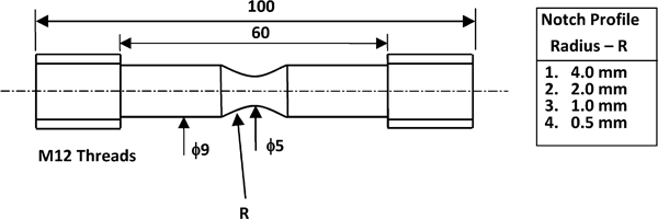
Schematic diagram showing geometry and dimensions of M12 threaded tensile specimens with different notch profile radii
Uniaxial tensile tests
The experimental high temperature tensile tests were carried out on a 200 kN Dartec servohydraulic machine. The required elevated deformation temperature was provided by the use of an environmental chamber. The mount assemblies from the base and the crosshead of the testing machine were allowed to pass through the top and bottom of the chamber respectively, ensuring that the sample deformation is contained within the chamber and therefore providing temperature homogeneity for the entire length of the deformed sample. The use of the thermal chamber enabled the experimental tensile testing to be conducted in a controlled thermal environment that closely reproduces the real industrial operating conditions used for solid state deformation processing.
After mounting the specimen, the thermal chamber was closed, and the heating process was initiated. The specimen was allowed to soak at the required deformation temperature for 45 min before testing. Following the heating period, the tensile deformation of the specimen was realised by moving the crosshead of the machine away from its fixed base at a constant velocity. At the end of the required level of deformation, the sample was immediately sprayed with appropriate aerosol freezer in order to preserve its structural and morphological characteristics. Subsequently, the deformed specimen was removed from the testing machine, and its final dimensions were measured. All the experimental tensile tests were performed at 160°C with a crosshead speed of 10−1 mm s−1 according to the procedures described above. Furthermore, tests for every set of conditions were repeated at least three times in order to ensure repeatability not only of the measured response but also of the resulting structural and morphological characteristics.
Deforming specimens up to fracture at elevated temperatures was only a small portion of the experimental tensile tests undertaken. It was also important to manually interrupt the tests at various stages of the process in order to allow the structural and morphological examinations of the specimen at different levels, especially during the early stages of the deformation process. Therefore, a series of interrupted tests at predetermined levels of deformation within the elastic and the early plastic regimes were carried out. The interrupted tests were performed in order to identify the level of deformation at which void nucleation occurs.
A total of three interrupted tests at different levels of deformation were carried out in addition to the final fracture case. Figure 2 shows a typical load versus crosshead displacement data for an R = 2·0 mm Delrin 150 NC010 specimen tested at T = 160°C with a crosshead speed of 10−1 mm s−1, with the deformation levels for the three interrupted test specimens indicated. Interrupted 1 refers to the very early stages of deformation, approximately halfway through the elastic deformation region, as shown in Fig. 2. Next, the test was interrupted near the onset of the plastic region, at the point where the maximum load was located (interrupted 2). Finally, the next interruption (namely, interrupted 3) was carried out when the sample started to plastically deform, near the point where the maximum load drop was located. The above locations were assumed to be critical in the formation of voids during the tensile deformation of POM.
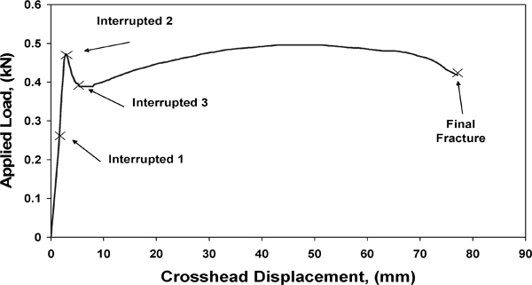
Tensile test of R = 2·0 mm Delrin 150 NC010 at T = 160°C with crosshead speed of 10−1 mm s−1 showing different levels of deformation at which tests were interrupted
Scanning electron microscopy
Scanning electron microscopy (SEM) investigations were undertaken to examine the morphology of the undeformed material compared to the observable damage in the deformed material. The sample material for the SEM investigations was obtained from the centre of the deformed specimen's gauge length transverse to the deformation direction. The undeformed material was also cut in the transverse direction from the core of the extruded rods.
The SEM studies were conducted on a Philips XL30 environmental SEM. Initially, the sample material was impregnated and cured in a Specifix-20 epoxy system for 8 h at room temperature. Bisphenyl-A as epoxy agent and 2-methyl-1,5,pentamethylene diamine diethylamino propylamine as curing agent were the two components of the curing epoxy resin. Small rectangular blocks were then machined from the resin–material system around the sample vicinity to facilitate the mounting of the sample in the microtome vice. A glass knife rotary microtome was used to cut the surface of the sample at room temperature. Next, the sample surface was exposed to vapour hexa-fluoropropanol with the intention of reopening any cavities closed during the preparation process. Finally, the specimens were mounted on long aluminium stubs and gold coated on an Emscope SC500 SEM coating unit. The SEM images were obtained parallel to the deformation direction when operating the microscope in the secondary electron mode at 20 kV accelerating voltage and a spot size of five. The original working distance of the sample was set at 150 mm but was subsequently reduced depending on the required focus and magnification.
Small angle X-ray scattering (SAXS)
The SAXS investigations were carried out on rectangular strips of 2 mm thickness machined from the middle of the POM specimen gauge length in the deformation direction. For studies on undeformed POM, rectangular strips of the same thickness were machined from the core of the extruded rods. The incident X-ray beam in the SAXS measurements was always perpendicular to the longitudinal axis of the specimens/rods.
The SAXS patterns were collected on a Siemens Hi-Star two-dimensional area detector using Cu Kα radiation of wavelength λ = 1·542 Å. The Cu Kα radiation was generated at 40 kV and 30 mA and collimated to 0·7 mm diameter. A fixed distance of 420 mm was applied between the detector and the sample, while the beam stop was positioned 150 mm away from the sample. The SAXS patterns were collected for 300 s at 20°C under vacuum. A background pattern without the sample was collected for the same duration at the end of each scan. The background pattern was then subtracted from the previously obtained sample pattern to provide the real scattering of the POM sample.
Results
Effective plastic strain
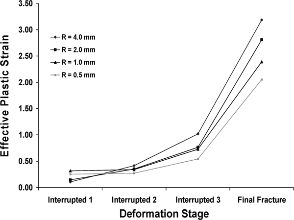
The initial and final specimen dimensions were measured using a Nikon V-16D profile projector at room temperature to a tolerance of ±0·001 mm. Then, the effective plastic strain at fracture or point of interruption was calculated from
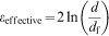
The average values of the effective plastic strains at fracture and at the respective interrupted stages are shown in Fig. 3. The trend of increasing failure strain with increasing specimen notch profile radius (decreasing stress triaxiality) is clearly demonstrated, as previously reported by other researchers using similar notched tensile specimens.12–15 The same trend was followed by the corresponding plastic strains at the different points of interruption, with the exception of the interrupted 1 tests. In this case, the elongation undergone by the shallow notched specimens was much lower than that of the sharp notch specimens and therefore resulted in lower values of effective plastic strains.
Average effective plastic strain at fracture or point of interruption for POM notched specimens deformed at 160°C with separation speed of 10−1 mm s−1 (R radius of notch)
Visual examination and SEM
Visual examination of the tensile deformed specimens was carried out in order to identify the existence of any stress whitening in the gauge length of the specimen. Semicrystalline polymers typically undergo stress whitening when deformed in tension at elevated temperatures, and this phenomenon is undoubtedly related to the formation of microvoids in the interlamellar amorphous regions of the deformed specimen due to the influence of the applied stress field.8
Specimens from the interrupted 1 tests appeared to be transparent with a very small degree of stress whitening found in the R = 1·0 mm and R = 0·5 mm notch profile specimens only. This observation indicates some limited void initiations during the interrupted 1 tests that correspond to the very early stages of deformation, approximately halfway through the elastic deformation region. On the other hand, stress whitening was clearly observed in all the specimens from the interrupted 2 tests, demonstrating that void nucleation and growth are well underway around the transition between the elastic and plastic deformation regions.16, 17
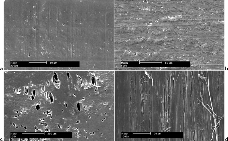
The surface morphology of the POM Delrin 150 NC010 extruded rods is presented in Fig. 4. It is not surprising to note that the as received material revealed a homogeneous, compact and featureless morphology with no evidence of voids or porosities. This can be attributed to the nucleating agent present in the material that prevents any void formation between the spherulites during processing.
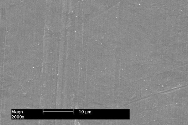
Images (SEM) of as received extruded rods of POM Delrin 150 NC010
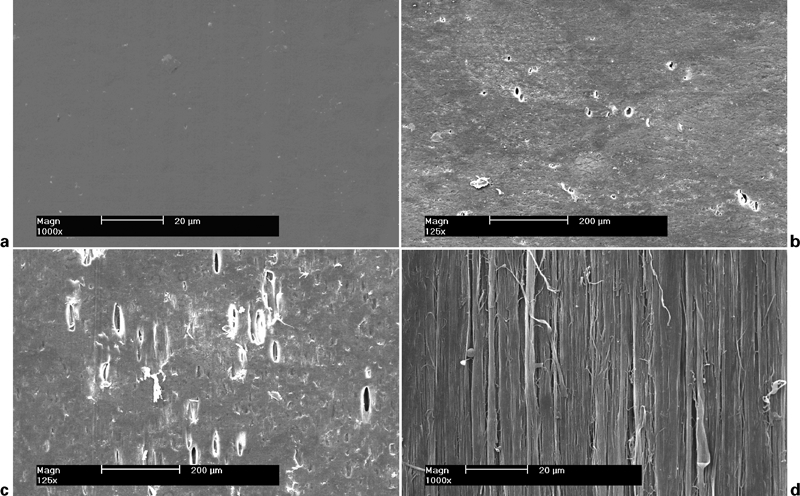
The SEM images obtained from the four different notch profiles of Delrin 150 NC010 are shown in Figs. 5–8. In accordance with the visual examination of the interrupted 1 specimens, no voiding is visible for the R = 4·0 mm and R = 2·0 mm notch profile radii ( Figure 5 Figs. 5a and 6a respectively). This could be due to the very low average effective strain undergone by these two specimens. In contrast, for the R = 1·0 mm and R = 0·5 mm notch profiles (Figs. 7a and 8a), the nucleation of some microvoids is evident at average effective strains of 0·32 and 0·25 respectively. While the formation of voids has been commonly observed in the plastic region of thermoplastic polymers under tensile deformation,18, 19 only G'Sell and Dahoun20 have previously hypothesised that this phenomenon could also be taking place in the elastic deformation region.
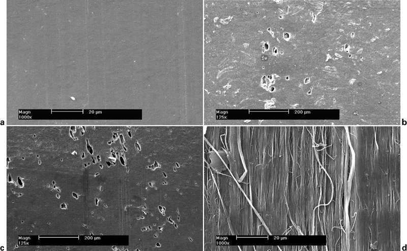
Images (SEM) of R = 4·0 mm Delrin 150 NC010 tested at 160°C with crosshead speed of 10−1 mm s−1
Images (SEM) of R = 2·0 mm Delrin 150 NC010 tested at 160°C with crosshead speed of 10−1 mm s−1
Images (SEM) of R = 1·0 mm Delrin 150 NC010 tested at 160°C with crosshead speed of 10−1 mm s−1
Images (SEM) of R = 0·5 mm Delrin 150 NC010 tested at 160°C with crosshead speed of 10−1 mm s−1
Moreover, all the interrupted 2 specimens confirm the presence of spherical voids scattered throughout the viewed area, although at different length scales due to the varying average effective strains achieved. Therefore, it can be concluded that voiding in Delrin 150 NC010 is definitely initiated at very low strains around the transition from the elastic to the plastic deformation regions, with the notch profile only affecting the size of the nucleated voids. In this transition region, the material has not yet strain hardened enough to prevent the continuing growth of voids.
From the SEM images obtained from all the interrupted 3 Delrin 150 NC010 notch profile specimens (Figs. 5c–8c), it is clear that the spherical voids observed in the interrupted 2 samples are now elongated more or less parallel to the deformation direction. It is obvious that the elliptical void growth is promoted by the applied tensile stresses.21 However, it is surprising to note that the voids in specimens with sharp notches (i.e. R = 1·0 mm and R = 0·5 mm) are considerably more elongated when compared to the voids in specimens with shallow notches, despite the fact that the latter have undergone significantly higher average effective strains. This finding suggests that the degree of void elongation is greatly influenced by the sharpness of the notch profile when the specimens are significantly plastically deformed, which is the case during the interrupted 3 tests.
Finally, Figs. 5d–8d present the surface morphology of the Delrin 150 NC010 final fractured specimens. Here, the elongated voids seen for the interrupted 3 test specimens, together with additional nucleated voids, act as stress concentrators that promote the fibrillation of the material. As a result, very elongated voids coalesce to form fibrils that ultimately lead to the final fracture of the deformed specimen. It is quite obvious from these SEM images that specimens with shallow notch profiles undergo considerably more fibrillation before they fail. In this case, the extent of fibrillation is a function of the average effective strain achieved, where, for example, the R = 4·0 mm specimen failed at an average strain of 3·19 while the R = 0·5 mm specimen failed at a much lower strain of 2·05.
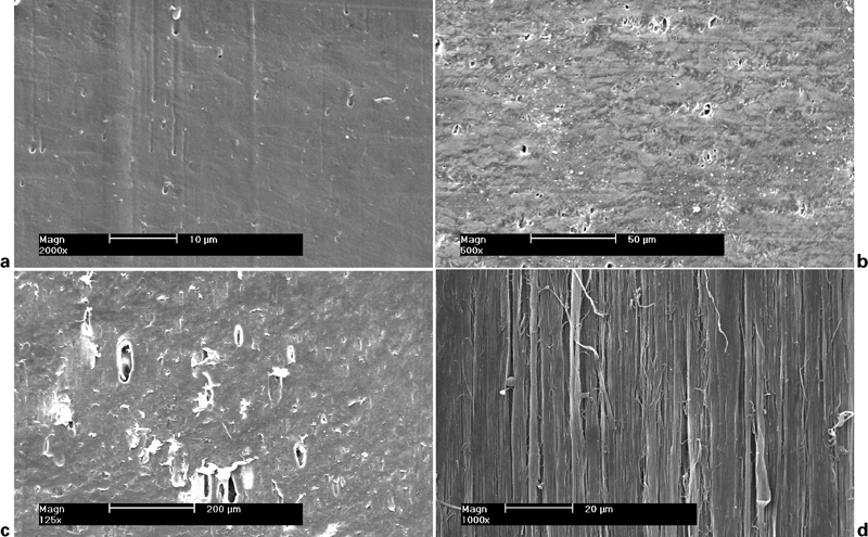
The fact that new voids are continuously nucleated while the deformed specimens are undergoing further elongation can be confirmed from the SEM images of interrupted 3 specimens shown in Fig. 9. Here, the microvoids visible at this high magnification are quite spherical with an average size in the order of several micrometres. On the other hand, the voids observed at lower magnifications for interrupted 3 specimens in Figs. 5c–8c are quite elongated with an average length of around 50 μm. This allows one to conclude that void nucleation is a continuous process during the tensile deformation of POM.
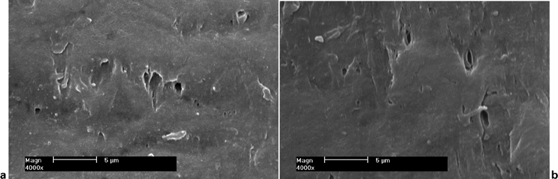
Images (SEM) of interrupted 3 Delrin 150 NC010 specimens tested at 160°C with crosshead speed of 10−1 mm s−1
Figure 10 compares the SEM images of the interrupted 2 different notch profile specimens. It is quite evident that at this deformation level, the specimen morphology of the specimens is influenced by the premachined notch profile. Hence, the sharp notch profiles (Fig. 10c and d) show a more homogeneous and compact surface morphology, with the sporadic existing voids being smaller, fewer in number and considerably less elongated than the ones present in the shallow profile specimens (Fig. 10a and b). This phenomenon is perhaps due to the different average effective strains undergone by the interrupted specimens, but unarguably, the strains achieved are determined by the respective specimen notch profiles; the fact that the triaxial stress parameter is greater for the sharper notches will encourage more spherical void growth.
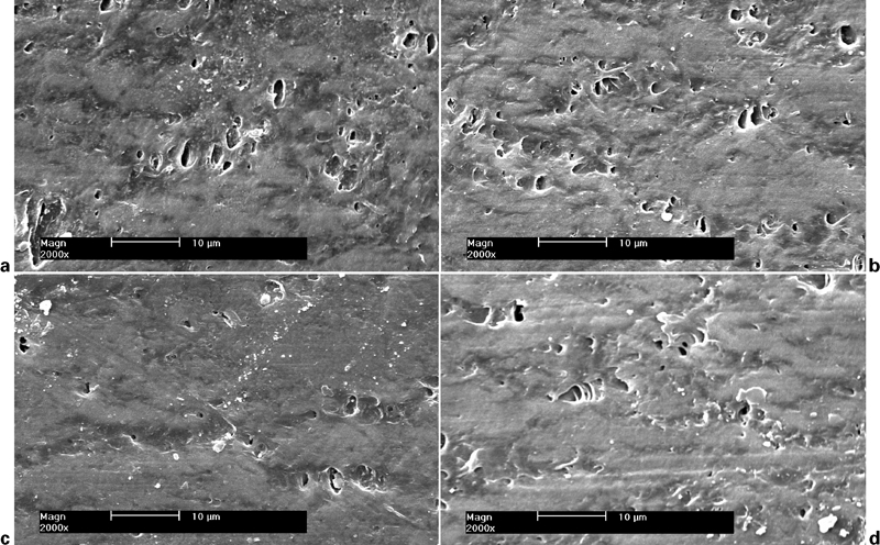
Images (SEM) of interrupted 2 Delrin 150 NC010 specimens tested at 160°C with crosshead speed of 10−1 mm s−1
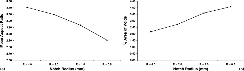
The effect of the notch profile on the measured mean aspect ratio and percentage area of a large number of identified voids for POM Delrin 150 NC010 is shown in Fig. 11 for the interrupted 2 specimens. It is quite obvious that at this deformation stage, both parameters generally increase with decreasing notch profile radius. However, for the sharper notch profile (R = 0·5 mm) specimen, the mean aspect ratio decreased somewhat compared with the R = 1·0 mm values. Again, this is indicative of the fact that there are noticeably more spherical voids nucleated in this small notch profile specimen as indicated by the increased area fraction of voids. However, these voids are less elongated than those encountered in the shallow specimen profiles, and this consequently reduces the average void aspect ratio.
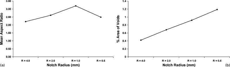
a mean aspect ratio and b area fraction of identified voids versus notch profile radius for interrupted 2 specimens tested at 160°C with crosshead speed of 10−1 mm s−1
Figure 12 presents the respective void mean aspect ratio and the percentage area evolution with the applied notch profile radius for the interrupted 3 specimens. In contrast to the interrupted 2 samples, the mean void aspect ratio of Delrin 150 NC010 was found to decrease with reducing specimen notch profile. In terms of the void area fraction, an increase in the sharpness of the specimen notch profile resulted in an almost linear increase in the percentage area of material occupied by voids. This enhanced void growth is thought to be due to the increased triaxial tension experienced by the sharp notch specimens.
a mean aspect ratio and b area fraction of identified voids versus notch profile radius for interrupted 3 specimens tested at 160°C with crosshead speed of 10−1 mm s−1
Small angle X-ray scattering
The SAXS patterns obtained for the isotropic POM Delrin 150 NC010 and at different stages of tensile deformation are shown in Fig. 13. These patterns were collected with the electron beam perpendicular to the extrusion and the tensile loading directions respectively. The SAXS patterns of the extruded rods showed a broad isotropic ring with no visible intensity variations. The isotropic ring pattern suggests that the crystalline lamellae and the amorphous regions of the material are arranged in a periodic manner.
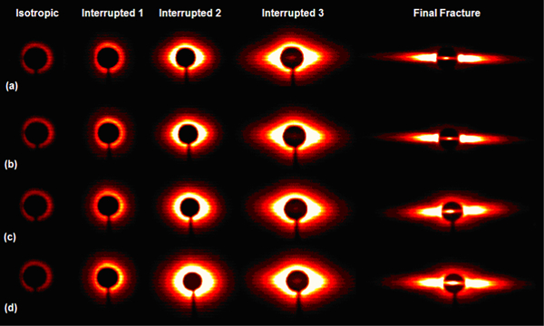
Small angle X-ray scattering patterns for as received and tensile deformed Delrin 150 NC010 tested at 160°C with crosshead speed of 10−1 mm s−1
The SAXS patterns from the interrupted 1 tests were similar to the isotropic ones with only a faint scattering variation in the equatorial direction due to the formation of some sporadic voids in the material. The variation was more pronounced in the sharp notch profile specimens, where the stress triaxiality parameter is higher. Further tensile deformation up to the transition between the elastic and plastic regions (interrupted 2 tests) resulted in clearly defused scattering along the equator. In accordance with the SEM findings, it can be concluded that voiding is definitely initiated in the material by this point. Again, the equatorial scattering increased with increasing applied stress triaxiality factor for the sharper notch specimens.
As the tensile deformation of the material is further increased, so does the degree of diffused scattering in the equatorial direction, as demonstrated by the interrupted 3 SAXS patterns. However, no significant variation in the scattering was observed for the different notched specimens examined. Ultimately, the SAXS patterns of the final fractured specimens resemble an equatorial streak, typical of the fibrillated structure of the material. The equatorial streak was found to be more elongated in the shallow specimens that failed at significantly higher strains and therefore allowed more deformation for fibrillation to take place before final fracture.
The long period L is calculated as a function of the scattering vector 

Figure 14 presents the material's long period evolution with the applied degree of deformation. It is obvious that the average axial long period increased during the interrupted 1 and 2 tests probably due to the corresponding increase in the lamellar spacing with the applied deformation. Similar findings for the long period evolution with increasing stretching have been previously reported.6, 18 Further material deformation caused an abrupt fall in the long period for the interrupted 3 and final fracture specimens to a value lower than that of the undeformed material. Previously, Mohanraj et al.6 have reported an abrupt fall in the long period during the die drawing of POM to an actual drawing ratio of RA = 2·6 or higher. Moreover, the calculated long period at each deformation stage was identical for all the adopted specimen notch profiles, with the exception of the interrupted 3 specimens. In this case, the long period reduction was greater in the sharper notch profile specimens.
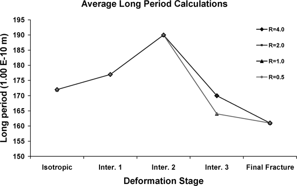
Long period variation with applied degree of deformation for Delrin notched specimens tested at T = 160°C with crosshead speed of 10−1 mm s−1 (R radius of notch/mm)
Finite element modelling
Finite element models
The four different axisymmetric models generated to simulate the uniaxial tensile test are shown in Fig. 15. These models reflect the different specimen geometries investigated throughout the experimental tensile tests reported in the section on ‘Experimental’. The specimen meshes depended upon the severity of the notch profile radius R (4, 2, 1 and 0·5 mm) machined at the centre of the specimen. In addition, because of the symmetry about the centreplane of the gauge length, only half of the specimen was modelled using axisymmetric elements.
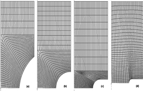
Finite element models simulating notched tensile tests
The plastic properties required to characterise the material's physical behaviour were established by uniaxial tensile tests on POM 150 NC010 at various strain rates and deformation temperatures.9 For the present work, piecewise linear approximations of the material's strain, strain rate and temperature dependent flow stress in the direction of loading were assumed for the deformation conditions examined. These linear approximations were used by ABAQUS to define the effects of strain rate and temperature on the plastic behaviour of the material. No account was taken of the known pressure dependence of the polymer flow stress in these simulations since the true stress–strain curves were measured at similar levels of negative (tensile) hydrostatic pressure (σm/σe = 0·33) to those experienced in the notched tensile tests.
The axisymmetric tensile models were created using coupled temperature–displacement four-noded elements for the material. Appropriate symmetry conditions were applied at the respective boundaries defining the specimen's behaviour during deformation. Figure 16 illustrates the complete loading and boundary conditions relating to the tensile models. It can be seen that movement was restricted at the two fixed ends of the model due to the symmetry along the two main axes, while no other constraints were placed at the free ends of the model. Axial loading was uniformly distributed at the top free end of the model, as indicated in Fig. 16.
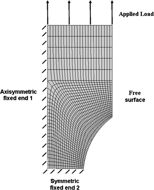
Loading and boundary conditions for notched tensile models
The simulation of the uniaxial tensile test was performed by ABAQUS in two consecutive steps. During the first step, the specimen was taken to the required deformation temperature and then maintained at that temperature for the duration of the process. Then, a constant velocity was applied at the free end of the model in the axial direction, forcing the simulated specimen to deform in tension up to the final fracture.
Results
Validation of the tensile finite element model and the assumed material properties was carried out by comparing the experimental and predicted load versus displacement behaviours, as shown in Fig. 17, for two different notch profile specimens. It is clear from the graphs that a very close agreement between prediction and experiment was achieved in the initial post-yield region, where the variations of the stress triaxiality parameter are investigated below. On the other hand, further specimen deformation resulted in significant greater lower loads recorded in the experiment compared with the finite element simulations. This phenomenon was attributed to the extensive voiding taking place in the material, which was not included in the finite element models. Void formation acts to reduce the apparent flow of the material as well as its ultimate strength. The effect was more pronounced in the shallow notch profile specimens (R = 4 mm) probably due to the greater volume of the material undergoing voiding.
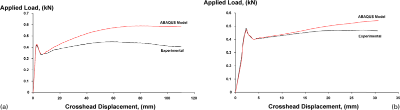
Measured and predicted applied load versus crosshead displacement for notched tensile specimens with notch profile radius
Figure 18 presents the predicted variation of mean stress to von Mises effective stress (σm/σe) at the centre of the specimen with effective plastic strain for the four different notch profile radii considered. A strong influence of the notch profile radii on the stress triaxiality parameter σm/σe is observed, with σm/σe increasing significantly with decreased notch radii. These results show how the level of stress triaxiality at the centre of the specimen initially increases with strain but then reduces with increasing levels of deformation. These findings are similar to those reported for polymers and other ductile materials.11–15
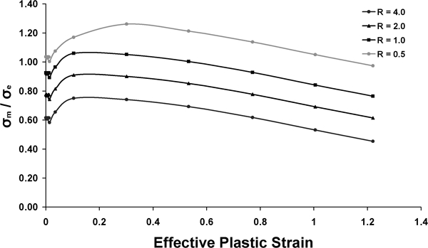
Predicted variation of stress triaxiality ratio σm/σe with effective plastic strain for Delrin notched specimens (R radius of notch/mm)
Discussion and conclusions
The results from the experimental tensile tests indicated that the average effective strain at fracture or different points of interruption was directly related to the notch profile radius of the specimen. Thus, the average effective strain of POM at fracture was found to increase with increasing specimen notch profile (i.e. with decreasing stress triaxiality parameter at the centre of the notch). In addition, accurate predictions of the local stress and strain conditions at the centre of the notch were obtained from finite element simulations of the uniaxial tensile test. The simulations predicted that the stress triaxiality parameter σm/σe increased with decreasing notch profile radius. However, the finite element models consistently overpredicted the load required to deform the material especially in the post-yield region. This was due to the fact that the simulations ignored the voiding taking place, which reduces the apparent strain hardening of the material as measured in the experiment.
The SEM investigations on the tensile deformed specimens clearly demonstrated the formation of some spherical microvoids in the elastic region of the material (interrupted 1 tests), especially in the sharp notched specimens. Stress whitening due to voiding was also apparent in the sharp notch interrupted 1 specimens. In addition, the long period of the material calculated from the SAXS patterns increased for the interrupted 1 test specimens compared with the undeformed material.
Voiding was definitely apparent from the interrupted 2 tests near the elastic–plastic transition, and the specimen notch profile influenced the size of the nucleated voids. In line with this finding was the increase in the mean aspect ratio and percentage area of the measured voids. Moreover, a further increase in the material's long period was observed.
Further plastic deformation (interrupted 3 tests) forced the previously spherical voids to elongate along the tensile direction, while the nucleation of additional spherical voids scattered throughout the surface of the examined area was also recorded. It was concluded that the nucleation of voids is a continuous process during the tensile deformation of the material. In general, the void percentage area and the mean aspect ratio increased with decreasing notch profile, except the mean aspect ratio of voids for the sharper notch specimens (R = 0·5 mm). In this case, the greater amount of newly initiated spherical voids when compared to the other specimen profiles led to a reduction in the mean aspect ratio. In addition, the SAXS investigations revealed a sudden reduction in the long period of the material.
A morphology transformation from the initial spherulitic to a fibrillar structure was observed in all the final fractured specimens investigated. While it was not clear precisely when this transformation took place, it was attributed to the growth and coalescence of voids to form a continuous fracture path. The degree of fibrillation was clearly more pronounced in the shallow notched specimens that failed at significantly higher strains and therefore allowed more time for the fibrillation process. The shallow profile specimens underwent substantial elongation before fracturing because the stress triaxiality factor at the centre of the notch is lower than it is in the sharp notched specimens. Moreover, the long period was further reduced to a value significantly lower than in the isotropic material.
These results indicated the critical importance of void initiation and grow in the large scale deformation and fracture of POM (and probably similar thermoplastic polymers) at elevated temperatures. Any analysis of this complex behaviour must take account of this voiding and its progression with increasing deformation to be realistic and accurate.