
Abstract
The various methods of self-sensing and self-healing developed within the Composite Systems Innovation Centre, University of Sheffield, are reviewed. Damage sensing using electrical resistance in carbon fibre reinforced composite or using the fibres as optical sensing elements in glass fibre reinforced composite is demonstrated. Amelioration of low level damage is demonstrated in both monolithic composite materials and sandwich structures using direct chemical reactions within the matrix without the use of encapsulants. These reactions can be activated by resistive heating of the material itself. The use of a combination of these techniques could create a truly smart structure able to both sense and repair damage and degradation.
Keywords
Introduction
With the increasing use of composites in critical applications with long service lives, it is desirable to develop smart composite systems with built-in capacities to detect and characterise mechanical damage and chemical degradation as well as the ability to self-heal. A smart material is defined as a material that has some additional functionality to its primary (usually structural) purpose. Typically, these additional functions fall into the categories of actuation, sensing or healing (for example, see Michaud,1 Virijenko and Verijenko2 and Pang and Bond3). Composite materials are, in general, well suited to the incorporation of smart functionality due to their methods of manufacture. A composite is a multicomponent system that enables the straightforward addition of smart elements. Additionally, the processing conditions are relatively benign (compared to for example metals), which allows the survival of such elements during manufacture.
Various methods of self-sensing and self-healing have been investigated within the Composite Systems Innovation Centre, University of Sheffield. This article is an overview of these varied technologies. Electrical and optical methods have been employed for detecting both damage to and chemical condition of the structure. Several solid state systems have been developed for healing matrix damage (cracks and delaminations) in monolithic composite laminates. A system has also been demonstrated that can self-repair damage to sandwich panels. Heat for these self-healing systems can also be produced within the material using the carbon fibres themselves as resistive heating elements.
Damage detection by resistance monitoring
A practical method of detecting barely visible impact damage in carbon fibre reinforced polymer (CFRP) composites using electrical resistance is under development. Changes in the intrinsic electrical resistance of the laminate are measured and related to the damage state of the structure. The electrical resistance in a CFRP laminate is an ideal parameter on which to base a damage detection system for two main reasons. First, damage is known to affect the electrical resistance of CFRP (see, for example Todoroki et al.4 and Angelidis and Irving5). These changes can occur either due to changes in the strain state of the material, for example relaxation in the residual thermal strains (carbon fibres are themselves piezoresistive in nature), or due to the damage directly disrupting the conductive pathways within the material. Second, the electrical conductivity of CFRP is highly anisotropic. This natural directionality within the material enables the source of the change in resistance, i.e. the damage, to be located.
In order to make measurements of the electrical resistance of the laminate, electrical contacts must be applied. These are usually applied to the surface of the laminate either as a conductive paint or as a sputtered metal coating applied subsequent to cure6, 7 or by co-curing with metal foil on the surface.4 The method used here is to embed the contacts during lamination to make contact with only certain plies within the laminate. In addition, to aid data interpretation, insulating interleaves of polyimide film are included to electrically isolate the plies with contacts (the ‘sensing’ plies) from the other plies. In the early work of Hou and Hayes,8 the contacts were simply copper wires laid into the laminate by hand. A schematic of this approach is shown in Fig. 1.
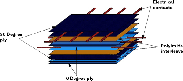
Schematic drawing of contacts incorporated into CFRP laminate8
More recently, this approach has been refined by incorporating the contacts in the form of flexible printed circuit boards, consisting of copper foil tracks on a polyimide film.9 These effectively take the role of both contact and interleave and allow far superior precision in the location and geometry of the contacts. An example of a panel produced, including such interleaves, is shown in Fig. 2.
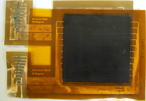
Carbon fibre reinforced polymer panel containing flexible printed circuit boards as interleaves
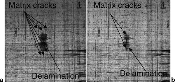
By recording voltage data for every pair of contacts while applying excitation currents individually to each pair of contacts in turn, full field data of the resistance of a ply can be obtained. By comparing the differences between the resistance before and after impact, maps of the changes in resistance can be produced, such as that in Fig. 3. In panels where sensing plies have been included in every ply of the laminate, maps of the changes in resistance can be produced for every pair of plies, examples of which are shown in Fig. 4.

Map of change in electrical resistance after damage: damage location is clearly visible as increase in resistance
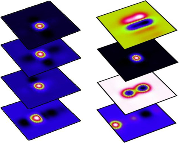
Maps of changes in electrical resistance in each pair of plies in cross-ply laminate impacted at 14·7 J (left) and 11 J (right)
Comparing the results from these laminates in which every ply had contacts incorporated showed that the greatest sensitivity to damage was obtained when the contacts were close to, but not at, the back face of the laminate.9 The effects of offsetting the contacts transversely were also examined. It was found that this did not significantly improve the sensitivity, although the area covered by a pair of contacts was increased. Preliminary results from scaling up the size of the panels are promising in that there is little significant drop in sensitivity observed for larger panels.
Resistance monitoring is therefore demonstrated as a practical and effective method to detect and locate barely visible impact damage in CFRP composite laminates.
Damage detection by optical monitoring
The suggested method employs the reinforcement fibres as optical self-sensing elements to detect damage in composites, obviating the need for the incorporation of additional sensing elements in the system. Previously suggested self-sensing schemes used either silica reinforcing fibres10, 11 or low refractive index resins.12, 13 In the present work, E-glass reinforcing fibres and a commercial laminating resin are used. It is shown that this system is capable of identifying and locating an impact and quantifying the extent of the resulting damage within a composite.
The fibres used in this study were commercially available plain weave E-glass cloth. The fibres were cleaned by heating in order to remove any organic contamination or coupling agents. One hundred parts by weight Araldite LY5052 was mixed with 38 parts by weight HY5052 hardener. This was further blended with 40 parts by weight propylene carbonate to lower the refractive index, as the refractive index of the composite matrix must be lower than the refractive index of the fibres, for them to act as optical waveguides.12
Impacts were performed using a falling impact tower using a 12·7 mm hemispherical indenter. The extent of damage induced in the panel was monitored by light transmission of the fibres. The light was launched into one edge of the panel using green light emitting diodes. The other edge was connected to an array of photodiodes, and the photodiode voltages were logged to a computer. A schematic of the experimental arrangement is given in Fig. 5.
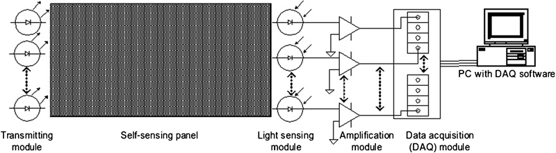
Schematic of sensing arrangement for impact damage detection
Real time results obtained during impact testing at 2·1 J impact energy are shown in Fig. 6. The results shown from an array of 20 sensors are normalised by light intensity detected by each sensor before any damage was induced; thus, the preimpact intensity value of each sensor is equal to 1. There is an immediate drop in the light intensity as soon as damage occurs to the transmitting fibres. Clearly, from this observation, the impact damage is resolved by the sensing system. These results show maximum damage in line with the impact (sensors 10–13) where all the fibres were fractured, giving no light transmission at all. The undamaged regions away from the impact area (sensors 1–7 and 17–20) show no signs of any reduction in light intensity after impact.
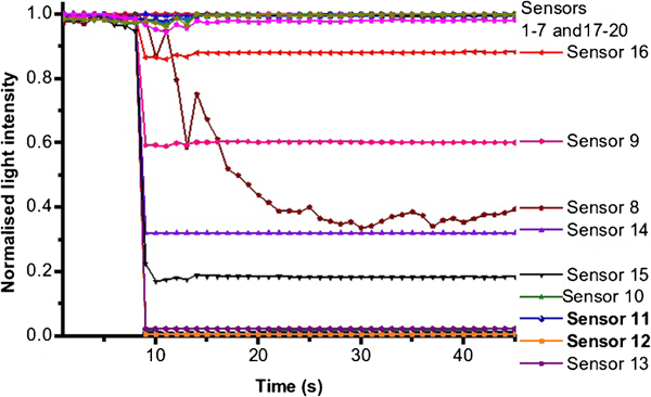
Results obtained during 2·1 J impact in centre of self-sensing panel
The normalised transmitted light intensity across the panel before and after impact is shown in Fig. 7. This clearly shows the spread of the damage in the centre of the panel, allowing the size of the damage to be assessed and its location to be identified.
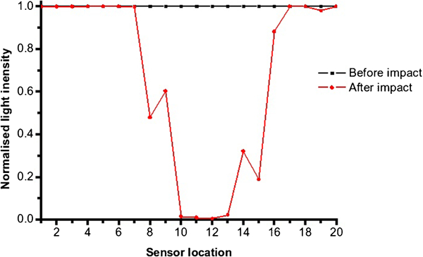
Graph showing normalised transmitted light intensity against sensor location before and after impact event: damage location is clearly observed
Assessment of the sensitivity of the sensor system was assessed using an impact energy of 0·7 J. The damage induced in the panel was barely visible to the naked eye. The impact impinged on sensor 11 in the panel, and the intensity was measured as before. From this test, it was clear that the first impact could be observed but was somewhat difficult to distinguish reliably from the noise in the measurements, as seen in Fig. 8. A second 0·7 J impact was, however, clearly identified. This shows that the sensor system clearly has the ability to identify low energy impacts that generate barely visible damage.
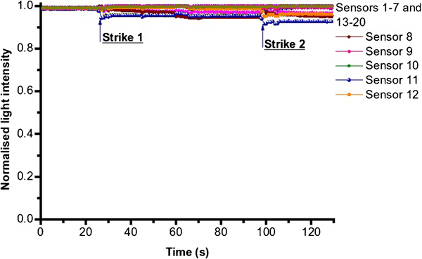
Response of sensors to two 0·7 J impacts: first impact is somewhat difficult to distinguish from noise in system, but second impact can clearly be identified
An optical self-sensing system to identify damage has been demonstrated, using a commercial resin, modified with a commercial reactive diluent and applied to commercial E-glass fabric. Further work to determine the length of transmission within the panel, minimum energy at which reliable damage identification can be undertaken and the variations in mechanical properties of the modified epoxy, is continuing.
Cure and chemical condition monitoring
Chemical health monitoring is complementary to the above discussed damage detection techniques, in as much as thoroughly optimised design criteria would mean that degradation of the matrix properties will be equally pertinent to the correct performance of a component. There are many equally critical elements of any structure that are unlikely to suffer impact or other mechanical damage but are potentially subject to environmental conditions deleterious to polymer properties. Furthermore, even if the presence of significant contamination causes no concern for matrix performance, it can still be indicative of more insidious degradation of the interface (or interphase) with the reinforcement, again adversely affecting the properties composite as a whole. Thus, we are aiming to develop a chemical sensing system universally applicable to any thermosetting polymer matrix composite using simple sensing elements that could be directly and easily incorporated during manufacture. Evanescent wave spectroscopy (sometimes termed reflectance spectroscopy) has the potential to fulfil this objective.
Evanescent waves have long been used routinely as a convenient sampling technique for liquids and soft matter;14only slightly more recent is the extension of the technique to use optical fibres instead of prisms, but it has remained the preserve of fluid analyses. Initial studies at the University of Sheffield demonstrated that unstructured, chalcogenide glass, optical fibres could be used as a fibre evanescent wave spectroscopy (FEWS) sensing element to monitor the cure of thermosetting polymer resins.15 While this process starts with a liquid medium, the system continues to function throughout cure, including the final stages, in which the resin is quite solid, that are of greatest interest to the process engineer. The logical extrapolation is that a fibre with sufficiently high temperature resistance could be directly incorporated in high performance commercial composites, not just to monitor cure but also subsequent chemical changes in the resin.
Other workers have demonstrated the implementation of FEWS in other forms to cure monitoring,15, 16 but to date, this work is its first application to monitoring chemistry in the solid state. Initial demonstrations have been carried out monitoring water absorption and desorption, since the process occurs rapidly and with significant effects on the material, in addition to which water has a very strong infrared signature.
Initially, the aim was to use existing fibres made from an unstructured chalcogenide glass. This would offer the requisite high refractive index in a material that is moderately easy to process and in which small quantities of commercial, albeit specialist, optical fibres are produced. Early work was conducted using optical fibres of arsenic selenide based glasses, made available by researchers at the University of Nottingham. A popular choice for research on infrared fibre optics, these glasses are relatively well characterised; they are also easy to process owing to the low melting and glass transition temperatures, the latter in the region of 120–150°C. However, in order to achieve a universal sensor, more temperature resistant fibres would be needed for higher performance resins. To date, no fibres are commercially available that could be expected to reliably withstand the cure cycle of a commercial composite prepreg with even midrange performance. Hence, the aim shifted in part to the identification of a suitable glass and fabrication of a small quantity of fibres therein. A number of compositions were examined in the GeS2–Sb2S3–PbS family described by Xia et al., 17which present an acceptably durable, temperature resistant fibre without the demanding processing requirements of glasses such as GLS.18, 19 Figure 9 shows a typical transmission spectrum; this glass family has an optical cutoff wavelength of ∼11·5 μm, allowing access to most of the near and mid infrared spectrum, which provide useful structural data on composition of organic chemicals. Refractive indices were determined to lie in the range of 1·9–2·4 depending on composition, with glass transition temperatures between 285 and 305°C.
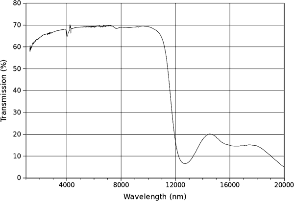
Infrared transmission spectrum of 6GeS2–3Sb2S3–PbS glass
These compositions (referred to hereafter as GSPS) therefore possessed the desired characteristic glasses in this family were synthesised, and the sensing fibres produced and incorporated into composite testpieces.
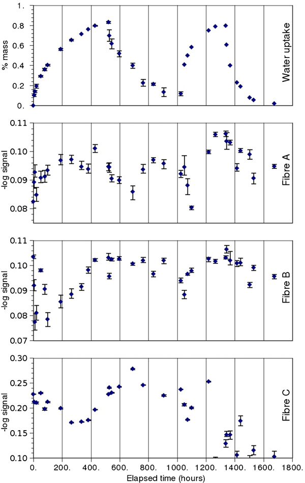
Figure 10 shows the first successful application of in situ evanescent wave spectroscopy in a cured composite; tracking water absorption and desorption in a room temperature cured epoxy resin, wet laid with unidirectional E-glass. The signal monitored has intensity at 1920 nm wavelength, corresponding to the centre of the primary attenuation band for the –OH functional group. The signal was normalised relative to two nearby non-absorbing wavelengths, error bars are given based on the noise level in a non-absorbing region.
In situ monitoring using FEWS: water uptake in two rods of room temperature cured Aradite 5052 reinforced with E-glass
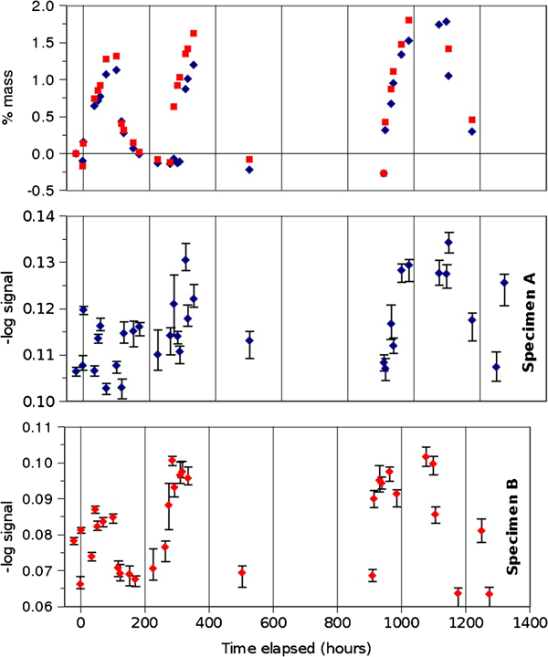
Figure 11 shows further promising results, tracking water absorption and desorption cycles in a thin plate of autoclave cured, carbon fibre reinforced epoxy; Cycom 977-2 unidirectional prepreg was used to demonstrate that the system can withstand some of the most thermally and mechanically aggressive cure cycles.
Monitoring water uptake in high performance composite (fibre A: laid under outer surface ply; fibre B: under first ply from surface; fibre C: under second ply)
Solid state healing
Highly crosslinked thermosetting polymers that are extensively used in structural composites are susceptible to microcrack formation when subjected to repeated thermomechanical loading. These microcracks can coalesce over operational lifetimes to eventually cause unexpected macroscopic fracture, including fibre/matrix debonding and ply delamination.20,21
We have developed a ‘diffusional solid state healing system’,22–25 which consists of a linear polymer that uniformly dissolves in epoxy resin of similar solubility parameter. The original linear healing agent of poly(bisphenol-A-co-epichlorohydrin) with average molecular weight of 44 100 g mol−1 should be reversibly bonded into the three-dimensional epoxy matrix through hydrogen bonding and become mobile above the minimum healing temperature for crack closure. Crack closure resulting from this healing mechanism can be seen in Fig. 12. The main disadvantage of this system was the high viscosity of modified resin containing the healing agent (HA).
The preliminary studies by Hayes et al.25 showed that 50–70% of the fracture energy G1C and fracture toughness K1C could be recovered for the modified resin containing up to 20 wt-% of healing agent. Work has also been performed to verify that phase separation is related to the reduction in healing efficiency at higher concentrations of HA.
The recovery or healing capability was optimised based on the calculation of fracture toughness from the compact tension (CT) test. The percentage recovery (RK) of loading strength from the CT test was calculated from the average value of the measured critical stress intensity factor K1C.
Typical load displacement curves from CT test results on both control samples of Epikote 828 resin and modified resins are given in Fig. 13. Following the initial testing, all of the samples were immediately healed at 140°C for 6 h and left to cool down to room temperature (25°C) at a rate of 2°C min−1. They were then retested using the same procedures. Figure 12
Micrographs showing example of glass fibre composite panel impacted at 2·7 J a before and b after healing cycle
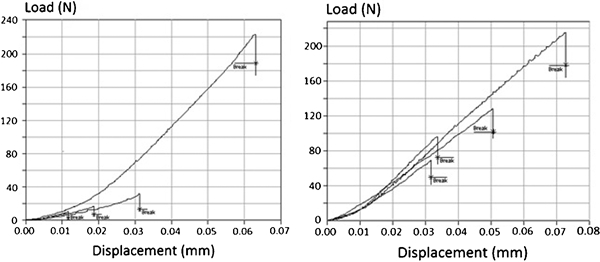
Typical load versus displacement for control (left) and modified resins (right) over three healing cycles
The value of fracture toughness K1C is calculated using the peak loads in the load–displacement curves. A predominantly linear load–displacement curve is seen up to the maximum load when the fracture spreads to the small central hole, and the tensometer was automatically stopped due to dramatically falling off load. This prevents the propagation of the crack or complete fracture.
The percentage recovery (RK) of 58·2, 39·7 and 27·4 was calculated from the load–displacement curve in Fig. 13 for the modified resin with 7·5 wt-% of treated HA and after repeated healing. The control resin also exhibited limited self-healing capability after a healing cycle due to some post-cure. The average value of K1C for the initial fracture of control resin was 0·77±0·01 MPa m1/2with percentage recoveries of 10·2, 5·8 and 4·6 following the first, second and third healing cycles. To compensate for this, the resin ‘Healing efficiency’ (HK) has been re-estimated by subtracting the percentage of healing that arises from the base resin. Thus, the HK contribution to healing from the addition of the healing agent can be examined. Focus has been on studying the effects of using different concentrations of HA in order to quantify the kinetics of diffusion and the efficiency of healing.
Figure 14 shows the healing efficiency based on the measured values from the CT test, containing a varying concentration of healing agent from 4·5 to 15 wt-% in modified resin. For the resin blends containing 4·5–8·8 wt-% of the healing agent, significant recovery of the healing efficiency was observed even after three healing cycles.
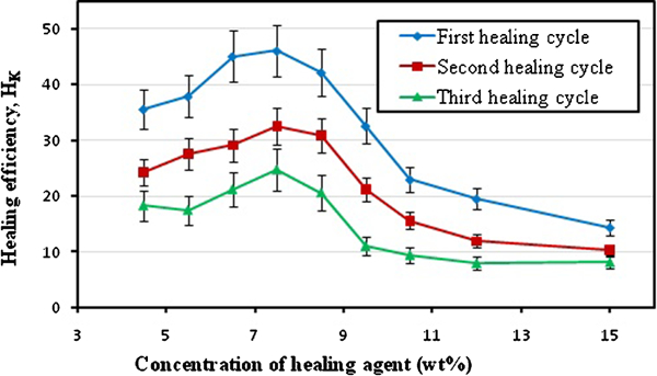
Healing efficiency of modified resin with different concentrations of HA with average Mw of 44 100 g mol−1: healing condition is set at 140°C for 6 h for each healing cycle
Work has also been performed on the rheology of these solid state self-healing resins. It had been observed from an early stage that handling of these resins before cure was extremely difficult and that modification would be required if these resins were to be used in manufacturing processes such as resin transfer moulding or injection moulding.
A log plot of the rheological profiles of the resins with a range of concentrations of healing agent is shown in Fig. 15, with the comparative data for the healability of the samples. It is clear that the increasing concentration of the healing agent has a profound effect on the viscosity and handling properties of the resin before cure.
Thermally reversible network polymers
Most self-healing methods involve the use of additional healing agents to be embedded within the material. An alternative approach is to construct a matrix resin with an intrinsic ability to heal itself. This can be performed by incorporating, within the polymer network, reversible chemical bonds that can reform upon the application of external stimuli (heat, light, acid, etc.). These bonds could be covalent, e.g. the carbonate bond,26 or formed through diels–alder reactions.27 They could also be ionic or supramolecular type interactions, such as the hydrogen bond that has been used with some success for polymer gels.28
A new area of research in the group builds upon the methodology established by Murphy et al., 29who describe the synthesis of a single component polymer material based upon dicyclopentadiene (DCPD) as a starting material, which has a huge potential for variation. The DCPD is a dimer of cyclopentadiene that forms through a thermally reversible diels–alder reaction. The DCPD can be cracked back to cyclopentadiene by heating to 150°C. It is possible to take advantage of this behaviour by tethering opposite ends of DCPD together with, for example, an aliphatic chain, as shown in Fig. 16.
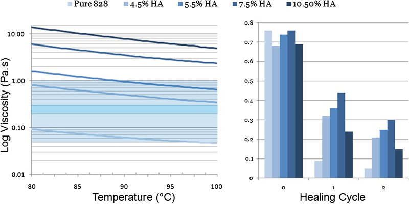
Effect of concentration of healing agent on rheological profile
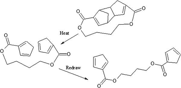
Cracking of dicyclopentadiene derived monomer
Upon heating, the dicyclopentadiene core undergoes a thermally reversible retro diels–alder reaction to produce monomers with reactive cyclopentadiene end groups. During cooling, the cyclopentadiene end groups react together to form a polymer (Fig. 17). The polymer backbone is also capable of reacting with free cyclopentadiene groups to form cross-links. Localised heating upon or even within a polymer structure could be used to repair and theoretically perfectly reform damaged areas. As the healing mechanism is intrinsic to the polymer, there is no parasitic weight. Importantly, no inclusions, voids, or catalysts required; this compares very favourably to for example a microencapsulation approach.
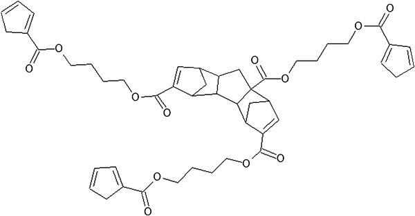
Illustration of one of diels alder three-way connections that can occur: cyclopentadienyl end groups will polymerise further
The primary aim of the work in this area concerns the synthesis and evaluation of additional monomers that use the cyclopentadienyl functionality but vary considerably in their backbone. The materials produced have potential applications, after optimisation and upscaling of the synthetic route, as reworkable engineering polymers.
A further aim is to produce variants of these monomers that are compatible with industrial epoxy formulations. Such a healing agent dissolved within a locally heated thermoset matrix can breakdown into mobile monomeric units, which are able to easily diffuse across microcracks without suffering from chain entanglements as with the present system. After cooling, the repair is facilitated by the reformation of the polymer network.
The synthesis shown in Fig. 18 is a modified version of the original approach involving the air free reduction in dicyclopentadiene to a reactive sodium cyclopentadienyl anion using elemental sodium followed by carboxylation with dry ice to form dicyclopentadiene dicarboxylic acid. The carboxylic acid groups are converted to the corresponding acid chlorides using thionyl chloride, and the final step is a bislactonisation reaction involving a variable diol. The synthesis has been modified in order to use a standard nitrogen/vacuum double manifold.
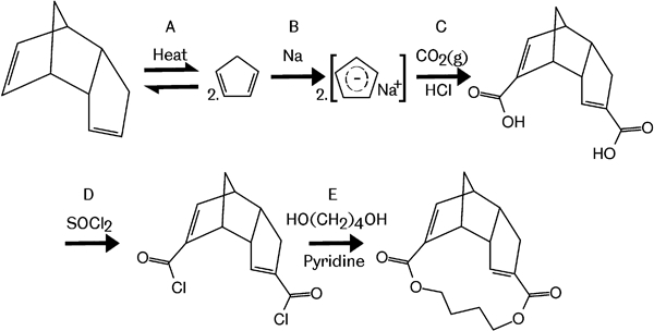
Synthesis of monomer unit, precursor to thermally repairable polymer
Alternative diols and bisphenols are being investigated instead of 1,4-butanediol in order to increase compatibility with existing resins. For example bisphenol A or bisphenol include 1,4-phenylene stiffening groups that may lead to increased modulus.
Sandwich panel healing
Sandwich composites are already an essential part of structural design, with ever expanding interest, particularly in the transport sector. While they offer great benefits, the fact remains that sandwich composites are highly susceptible to impact damage but difficult to repair. Effects and repair schemes have been well documented in many specific scenarios and in broader texts, such as Abrate.30
The mechanical damage caused by an impact almost universally comprises three aspects: skin fracture, skin disbond and core crushing. Standard repair schemes as a minimum require the replacement of an entire section of front face and core. It is argued that such a degree of time and expense is not always warranted or even possible for minor damage in many applications. This research seeks to offer an alternative solution by building in the ability to conduct a simple, non-invasive repair, hereafter referred to as ‘healing’.
In an impact damaged sandwich structure, theory dictates that a good deal of structural strength may be regained by reattaching the skin to the core. Other researchers have successfully demonstrated this effect by entirely different means,31 albeit at significant cost to the weight and complexity of manufacture. Novel interlayer materials are being developed that can fill the void left by core crushing and reinstate adhesion between skin and core. Following impact damage, the repairing function is activated by moderate heating of the affected area to a point above service temperature, causing local volume expansion and flow of the interlayer material.
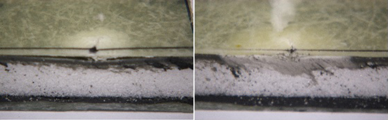
Figure 19 shows an encouraging result from the very first proof of principle. A photograph of the impacted surface illustrating the fact that with a reasonably thick interlayer, even the most severe damage, verging on complete perforation, can be pushed out.
Severe impact damage to CFRP skin over foam core with and without activation of healing layer (impact energy of 7 J)
Current research is focused on elastomeric interlayer formulations with a distinct softening point lying above a large proportion of composite operating conditions while being low enough to present minimal risk of skin material degradation.
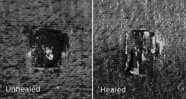
Figure 20 shows a composite in which the interlayer has been precured onto the core material, with E-glass reinforced polyester wet laid on top. The impact has permanently deformed a volume of the core and disbonded the skin over a considerably wider area yet left little apparent damage on the surface. After healing, the interlayer has expanded, filling the roughly conical indentation and rebonding to the skin.
Impact sites on polyester skinned panel: as impacted (left) and after healing (right)
The generic chemistry and particular formulation of the interlayer cannot be discussed at present due to a continuing patent application but results in excellent adhesion to most substrates and means that the interlayer can be processed at low to moderate temperature. It is thus easily incorporated (for example laid up as a part cured sheet or sprayed in situ) as the structure is assembled, replacing any other adhesive used between core and skin. To date, panels have been successfully prepared using the interlayer as adhesive, precured and co-cured with an E-glass reinforced, mid temperature epoxy skin.
Figure 21 shows the mechanical performance of a co-cured system consisting of eight-ply skins of E-glass reinforced epoxy resin before and after an 8 J impact and after healing. Impact has reduced the in plane compressive strength of the panel by ∼40%, but even in this unoptimised system, healing restores the panel to 80% of its original strength. In this particular system, the addition of the interlayer gave only a 3% increase in panel thickness and 8% increase in areal density.
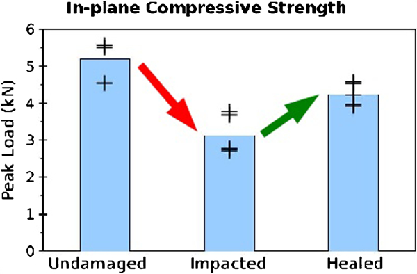
In plane compressive strength of co-cured sandwich panel before and after impact and healing
As discussed elsewhere in this paper, approaches are being developed3, 23, 32 to create fibre reinforced polymers embodying a self-healing capability, which might be used as the skin of composite sandwich panels. Furthermore, all of the aforesaid healing systems for fibre reinforced resin systems can currently only repair closed or very narrow cracks. The concept presented here is distinct from these, yet complementary in as much as it could provide a closing force on skin matrix cracks, improving the efficiency of any self-healing process contained exclusively in the skin.
Thermal activation of healing
Since the healing systems presented earlier in this paper all require thermal activation of the healing process, a self-heating system has been investigated. Carbon fibres are electrical conductors with a moderately high resistance, which makes them applicable as heating elements. The self-sensing system described in the section on ‘Damage detection by resistance monitoring’ requires the incorporation of electrical contacts into the structure, which can also be used to apply a heating current. It has been found that the application of higher electrical currents than would be used for sensing (currents on the order of amperes as opposed to microamperes) results in heating of the panels. By applying currents to pairs of contacts in two orthogonal plies, the heat can be highly localised to the damage area, as shown in Fig. 22. It was found possible to achieve spot temperatures at the location of the damage of up to 150°C at relatively modest currents of 1–2 A and voltages of 1·5–3 V.
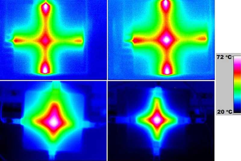
Thermal images of CFRP panels heated by electrical currents applied to embedded contacts: 2·5 mm wide contacts were used for panel shown in top row, before impact (left) and after impact (right); and 10 mm wide contacts were used for panel shown in bottom row, before impact (left) and after impact (right) (1 W of electrical power applied in every case)
It was noted that high contact resistances caused undesired local heating at the contact locations. This effect was minimised by increasing the width of the contacts, as shown in Fig. 22. It was also noted that the damage itself had a beneficial effect in terms of localising the heating. The higher resistances resulting from the damage increased the localisation of the heating, as can be seen in the differences in the left and right hand thermal images in Fig. 22.
Conclusions
Work is currently continuing at the University of Sheffield in several aspects of introducing smart functionality into composite materials. Monitoring of both chemical and mechanical conditions of the composite has been demonstrated, and in many cases found highly effective. Amelioration of low level damage has been successfully demonstrated in both monolithic composite materials and sandwich structures. The use of a combination of these techniques could create a truly smart structure able to both sense and repair damage and degradation.
Footnotes
This paper is part of a special issue on Deformation and fracture of polymers and their composites