
Abstract
In this study, the compressive behaviour of carbon fibre reinforced plastic quasi-isotropic laminates and sandwich panels with carbon fibre reinforced plastic face sheets and syntactic foam core has been investigated. Experimentally determined open hole strengths have been compared with theoretical predictions obtained by applying a linear cohesive zone model. The unnotched compressive strength has been experimentally determined, and the in-plane fracture toughness has been analytically predicted as input parameters of the model. Buckling phenomena occurred on some specimens, and they have been taken into account. Evaluation of macroscopic failure modes in compression tests on unnotched specimens led to a better understanding on the advantages of the analytical model and on the possibility of applying the model to sandwich structures. The experimental results were in good agreement with the analytical prediction by the Budiansky–Soutis–Fleck cohesive zone model, and the difference between theoretical and experimental open hole strengths of Syncore sandwich panels was <9%.
Introduction
The most frequently observed modes of failure in unidirectional laminates loaded in compression are fibre microbuckling, fibre kinking and delamination. Rosen1 analysed fibre microbuckling in glass/epoxy laminates under compressive loading. For unidirectional composites subjected to compression, he envisaged two possible modes of failure, i.e. extension mode and shear mode. Efforts to improve the microbuckling model include the investigations of microbuckling near a free surface2 interfacial debonding,3, 4 fibre waviness or misalignment3–7or material non-linearity.7–10 Wisnom used a non-linear matrix shear modulus and an assumption of initial fibre misalignment to calculate the change in compressive strength with fibre misalignment. In addition, Wisnom incorporated the matrix non-linearity and fibre misalignment into a numerical model to assess the effects of lateral constraint by the grips on composite failure.6, 7
Kinking is deformation localised in a band across the specimen width in which the fibres have rotated and the matrix has undergone large shearing deformation. Experimental works carried out with carbon and glass fibres reveal fibre breaks at the boundaries of the kink band. Argon was the first to analyse the kinking phenomenon; his analysis was based on an assumption of a local initial fibre misalignment, which leads to shearing stress between fibres that acts to rotate the fibres, increasing the shearing stress and leading to instability.11 Budiansky investigated elastic kink formation in unidirectional composites and found Rosen's shear mode prediction to be correct for kink bands with boundaries perpendicular to the loading axis. His analysis of kinking at other angles led to the conclusion that kink bands inclined at 0° resulted in the lowest compressive stress, so that kinks should form in bands perpendicular to the loading axis, contrary to the experimental evidence.12 These results led Budiansky to include the effects of plastic deformation in the analysis using a matrix model that exhibits elastic/perfectly plastic behaviour in shear. An initial imperfection is then expected to cause a local stress concentration, which, in tandem with the non-linear (softening) matrix shear, leads to failure. Fleck and Budiansky compared the theoretical compressive strength prediction of Argon11 and Budiansky12 with the experimental results, and they indicated that plastic microbuckling was the dominant failure mode in composites with polymeric matrixes.13
Advanced composites, such as carbon fibre reinforced epoxy matrix laminates with a central open hole, result in compressive strength, which is <40% of that for the unnotched material. Furthermore, the failure stress cannot be predicted from the elastic stress concentration factor, as it has been observed that the high stresses at the hole boundary initiate local failures, which result in a redistribution of stresses.14
In this study, the experimental data on open hole laminates show that the notched strength lies above the predicted ideally brittle behaviour due to the development of subcritical damage in the form of fibre microbuckling accompanied by matrix cracking of the off axis plies, matrix plasticity and delamination between plies. In previous works,14–19 it has been observed that the damage initiates by a combination of fibre microbuckling in the 0° plies and delamination. Fibre microbuckling is the main failure mode for this kind of laminates under uniaxial compression: the 0° fibres break at two points, creating a kink band inclined at an angle β (Fig. 1); the microbuckling zone starts from the edge of the hole, and it propagates with increasing applied load like a fatigue crack in metals.14, 15Soutis et al.14–19 investigated the compressive behaviour of several multidirectional specimens containing single hole and developed a theoretical model based on the observation that the fibre microbuckling behaves like a crack loaded on its faces, assuming a form of stress–displacement bridging law across the crack faces. Soutis’ model has shown that it is possible to predict the notched strength of carbon fibre reinforced laminates if the unnotched strength of the laminate and the in-plane fracture energy associated with fibre microbuckling are known.16
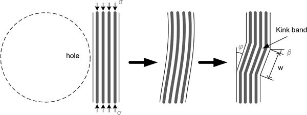
Geometry of 0° buckled fibres at edge of hole (β: boundary orientation angle; φ: inclination angle; and w: kink band width)19
As input parameters, unnotched strength and in-plane fracture energy need to be determined. Several analytical models, empirical equations and graphic methods have been developed for unnotched strength and in-plane fracture energy predictions. The unnotched strength could be predicted analytically by means, for instance, of Budiansky kinking theory or by means of new graphic methods as those described by Jumahat et al., 20 where the unidirectional unnotched strengths of different toughened composite laminates were successfully determined through the shear stress–shear strain response of the composite. The in-plane fracture energy could be predicted by the Budiansky prediction of the crack overlap displacements13 or through an empirical equation by Jelf and Fleck (fracture energy calculated by critical crack closing displacement).17
In this study, the unnotched strength from experiments and analytical predictions developed by Budiansky has been implemented and compared in the analytical model, together with the in-plane fracture energy predicted analytically.
When used in sandwich constructions, composite materials present definite advantages compared with monolithic laminates like improved stability, higher bending stiffness, higher strength/weight ratio, excellent capability of acoustic and thermal insulation and high capability of absorbing impacting energy. The cohesive zone model was also successfully applied by Soutis and co-workers to predict the mechanical behaviour of notched glass fibre epoxy/honeycomb sandwich panels loaded in uniaxial compression.21They analysed the experimental strength data obtained by Toribio and Spearing22 for E-glass/epoxy face sheets bonded to Nomex honeycomb core and loaded in compression, finding a good agreement between theoretical predictions and experimental data in terms of unnotched and open hole compressive (OHC) strengths.
In this paper, monolithic carbon fibre reinforced plastic (CFRP) laminates and syntactic core sandwich panels are the material systems under study.
The main objective of this work is to evaluate how the presence of a soft core material (Syncore) could affect the compressive behaviour of sandwich structures with CFRP face sheets in terms of failure modes for unnotched and open hole specimens and if it is possible to apply the Budiansky–Fleck–Soutis analytical model on such structures. In a pure edgewise compressive loading, the contribution of the soft core to the strength of the material is negligible, and the mechanical response of the sandwich structure in compression is face sheet dependent. If the core material is perfectly bonded to the CFRP face sheets under a compressive load, then a more stable failure mode is observed, and the overall instability is not expected. Alignment of the specimen with the load direction is another important issue to be considered in order to carry out compressive tests and to measure the compressive strength of the material system. Nevertheless, imperfections in the face sheet/core interface, due to an imperfect adhesion during the manufacturing process and the presence of flaws, could lead to debonding between face sheet and core during compressive loading. As the compressive load increases, the single face sheet would bear most of the load, and it would experience global bucking that leads to a premature failure of the structure. These phenomena need to be taken into account when the unnotched strength is estimated since this is used as an input parameter in the analytical estimation of OHC strength of sandwich structures when using the Soutis–Fleck model.
Experimental tests
Material and lay-up
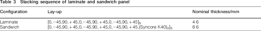
The composites under analysis are carbon fibre reinforced epoxy quasi-isotropic laminates and sandwich panels with a syntactic core foam and CFRP face sheets. The material used for the CFRP laminate is Toray tape prepreg, form 3, grade 190, of intermediate stiffness carbon fibres in a toughened epoxy resin. Owing to the commercial restrictions by our sponsors (Alenia Aeronautica S.p.A., Italy), the exact type of the composite system is not provided, and in Table 1, the elastic properties of a very similar lamina are shown. The monolithic laminate is made of 24 plies with a nominal thickness of 0·193 mm. The syntactic foam is a ‘Henkel Syncore 9872·1, K40’. Syncore is a low density syntactic material that combines a matrix resin system with low density, high strength glass microballoons. It is supplied in a film form, and it is assembled to the fibre reinforced epoxy prepreg; once assembled, the prepreg/Syncore sandwich is bagged using standard vacuum bag lay-up procedures and cured using the manufacturer's recommended cure cycle. The main mechanical properties of Syncore foam are presented in Table 2. The prepreg tapes were laid up by hand using a stacking sequence [(0/−45/90/45/0/−45/90/45/0/−45/90/45)S] and were fabricated at Alenia Aeronautica S.p.A., Foggia, Italy. The laminates were then inspected ultrasonically to establish the laminate's quality and void content. Table 3 shows the lay-up of the monolithic laminate and the sandwich panel.
Properties of unidirectional CFRP lamina

Properties of syntactic foam
Stacking sequence of laminate and sandwich panel
The CFRP and Syncore sandwich specimens have been obtained from laminates with a final in-plane geometry as prescribed in the Standards EN 603623 for the determination of static unnotched and OHC strengths.
Before cutting the specimens, carbon epoxy end tabs were bonded on two of the panel edges in order to avoid the damage of the fibres into the gripping device of the test machine. Several 130×40 mm specimens with a gauge length of 50 mm were cut from 4·6 and 8·6 mm thick panels. Holes with a 6 mm diameter were drilled on 10 specimens. At least five specimens were tested for each configuration.
Test plan and experimental set-up
Static compressive tests were carried out on 10 unnotched and 10 open hole specimens of CFRP monolithic laminate and Syncore sandwich panels. Tests were performed on a servohydraulic test machine with a 100 kN load cell at a displacement rate of 1 mm min−1. The specimens were loaded by shear action using compressive wedge grips. A 25 mm length extensometer was used in all the unnotched and open hole tests.
Attention was paid to the set-up procedure and particularly to the alignment of laminate and sandwich specimens with the loading axis. In most of the specimens, unidirectional strain gauges were applied on both faces (back to back) in order to monitor the strain behaviour up to failure and the alignment of the specimen (Euler Buckling). Strain gauge signals were acquired by System 5000, Micro Measurements, USA.
Unnotched and OHC strengths and the equivalent elastic modulus were measured.
As the CFRP face sheets bear the main compressive load, the strengths for
Syncore panels were calculated with respect to the face sheet section area
in order to be able to compare directly the mechanical properties of the CFRP
monolithic laminates and sandwich panels. Therefore, the compressive strength
of sandwich panels has been calculated without the contribution of the foam

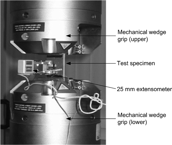
Compressive loading of sandwich panel in servohydraulic test machine
Test results
First, unnotched compressive tests were carried out. The stress–strain curves in Fig. 3 show the typical mechanical behaviour of the monolithic laminate and sandwich panel when loaded in uniaxial compression. Both configurations show a relatively brittle behaviour, the curves change their slope at ϵ%≈0·2 and the strain to failure is in the range of 1·0–1·2%. However, it can be seen that the sandwich panel shows higher stiffness, suggesting better stability and less out of plane buckling that may occur in the thinner monolithic laminate. This out of plane deflection can lead to an earlier failure and hence lower unnotched strength. Figure 4 shows a typical fracture pattern for unnotched Syncore sandwich panel under compression load. Almost all the unnotched sandwich specimens fail in the gauge length, but near the grips as stress concentrations occur at the edge of the clamping system. Delamination, fibre breakage and matrix failure are observed in the overall failure pattern of the face sheets. The syntactic foam Syncore HC 9872·1 shows qualitative features typical of frictional pressure dependent geomaterials: a crack propagates through the foam core along a crack band inclined to an angle of ∼45° with respect to the loading axis. Core skin debonding was also observed. In two Syncore specimens, this mechanism, linked to the presence of flaws in the interface between the core and the face sheets, resulted in premature failure of the panel. Once the core debonds from the skins, the panel stiffness/stability is reduced, and the face sheets fail at lower applied loads due to buckling and hence lower overall compressive strength of the Syncore sandwich.
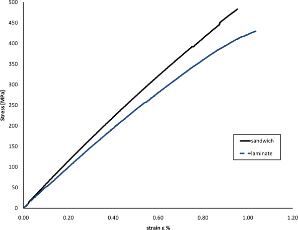
Average stress–strain curves for laminate and Syncore sandwich panel (unnotched tests)
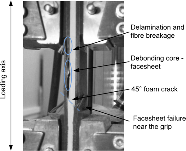
Typical overall failure pattern for unnotched Syncore sandwich panel in compression
Then, static compressive tests were carried out on 10 open hole specimens of CFRP laminate and Syncore sandwich panels. The stress–strain curves in Fig. 5 show the mechanical behaviour of the open hole monolithic laminate and sandwich panel when loaded in uniaxial compression. The strain data were measured by a 25 mm unidirectional extensometer placed in the gauge section of the specimen such that it is not influenced by the presence of the hole (inset in Fig. 5). The curves change their slope at ϵ%≈0·4%, and the strain to failure is in the range of 0·7–0·8%. It appears that the sandwich panel provides a better stability (stiffer), and as a result, the composite skins fail at a higher stress. Figure 6a and bshows the open hole failure mechanisms. All the specimens failed in the net section, where the stress concentration due to the presence of the hole is high. Again, debonding between foam core and face sheets and a crack propagation through the foam core along a 45° inclined crack band are observed in Syncore specimens. However, in open hole compression tests, the hole dominates the final failure, and the global buckling phenomena have a smaller effect in ultimate strength. The compressive strength for open hole specimens was calculated with respect to the gross section and the net section area. The mean values of compression strength and their coefficient of variation percentage (CV%) are shown in Table 4.
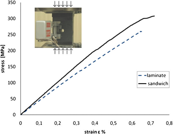
Average stress–strain curves for laminate and Syncore sandwich panel (open hole compression tests)
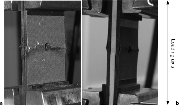
Typical overall failure pattern for open hole compression
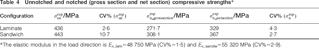
Unnotched and notched (gross section and net section) compressive strengths*
 /MPa
/MPa
 /MPa
/MPa /MPa
/MPa
*The elastic modulus in the load direction is Ex_lam = 48 750 MPa (CV% = 1·5) and Ex_sandw = 55 320 MPa (CV% = 2·9).
Buckling phenomena and discussion
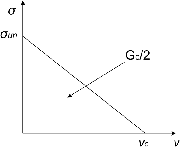
As the loading configuration under analysis is compression (Fig. 7), some considerations need to be made on the buckling phenomena that can occur when unnotched tests on sandwich structures are carried out. At least four possible failure modes exist for sandwich columns (Fig. 8): Euler macrobuckling, elastic core shear macrobuckling, plastic microbuckling of the face sheets and face wrinkling.24
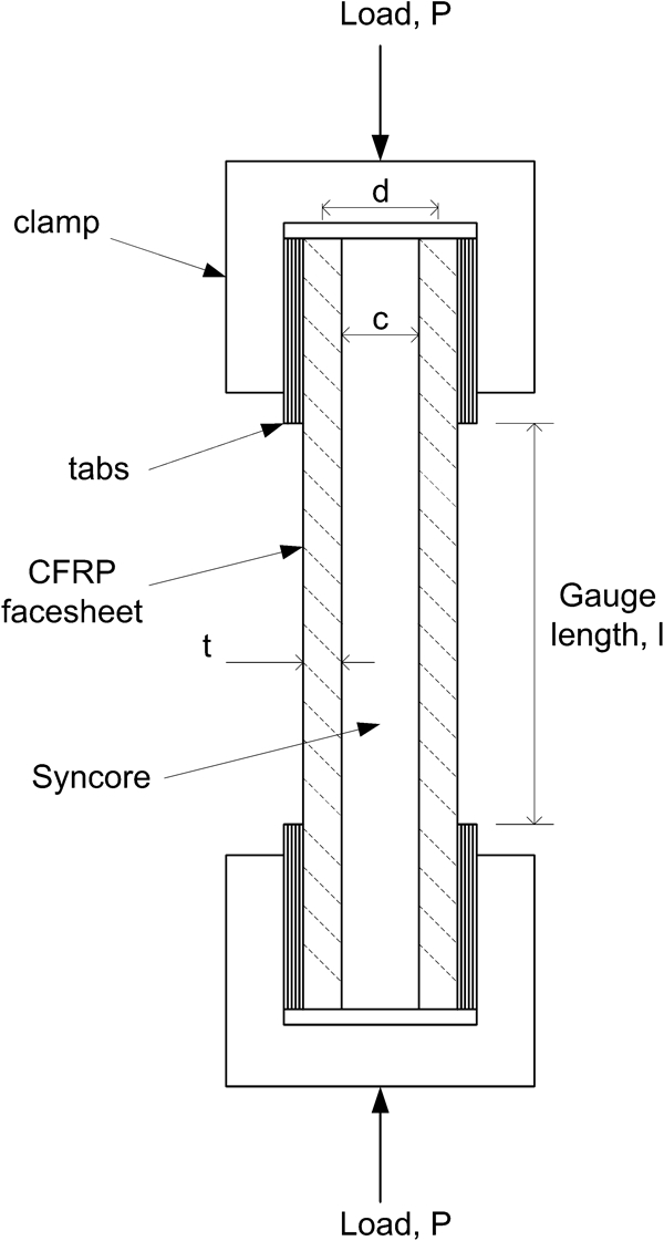
Sandwich column subjected to end compression loading
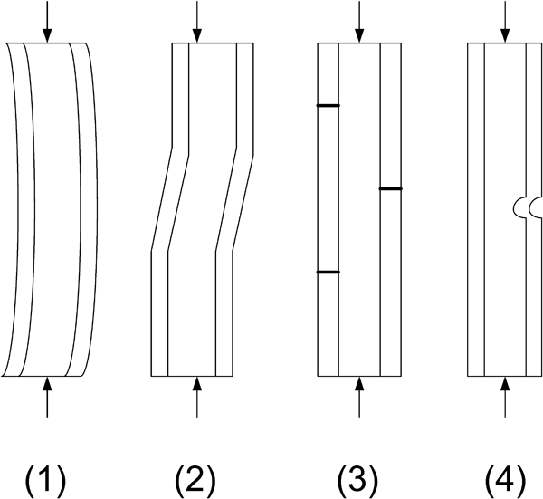
Possible failure mode patterns
As it will be explained later, we assume that the plastic microbuckling of the face sheets is the main failure mode for this kind of laminates under compression. Nevertheless, particular attention should be paid to the other buckling phenomena previously mentioned.
The Euler buckling load PE is

Syncore sandwich properties for determining Euler buckling load (parameters defined in Fig. 7)

The overall dimension of the sandwich specimen has been correctly selected
so that global Euler buckling will not be possible as
 .
.
The core shear buckling load Ps is set by the
shear stiffness of the core


For the syntactic core under analysis, Gc = 1034 MPa, so Ps = 260·5 kN, which is higher than the critical load to failure of the sandwich panel under analysis.
The compressive bifurcation stress in the face sheet for wrinkling, i.e.
the short wavelength elastic buckling of the face sheets, is given by25
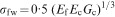
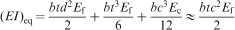
An important source of concern is the effect of debonding between core
and face sheets that could lead to single face sheet Euler buckling if
 .
.
This phenomenon occurred in two unnotched compressive tests on Syncore sandwich panels. From the previous data, it should be noticed that if the debonding between face sheets and core goes through the width of the specimen (l = 50 mm), the face sheet will bear all the load, and it will follow instantaneous failure when buckling critical stress is reached. For the single face sheet
(EI) = 2 106 598·4
MPa mm4
Buckling failure of face sheet observed in unnotched sandwich panel (specimen A 1_5): load = 62 kN applied
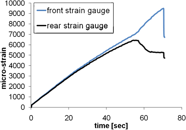
Front and rear strain history in unnotched sandwich panel presented in Fig. 9
In the following sections, the OHC strengths for the monolithic laminate and the sandwich panel are calculated analytically.
Analytical model
The linear cohesive model by Soutis et al.14–19, 21 predicts the compressive behaviour of multidirectional CFRP specimens containing a single hole, and it is based on the observation that the main failure mode of multidirectional laminates is due to plastic fibre microbuckling: microbuckling behaves like a crack loaded on its faces, assuming a form of stress–displacement bridging law across the crack faces. Mathematically, a crack replaces the microbuckling emanating from each side of the hole. The compressive stress σ carried by the microbuckled material is equivalent to a normal traction load on the crack faces. In addition, the cracked specimen experiences a remote compressive stress S that drives the microbuckling growth (Fig. 11).
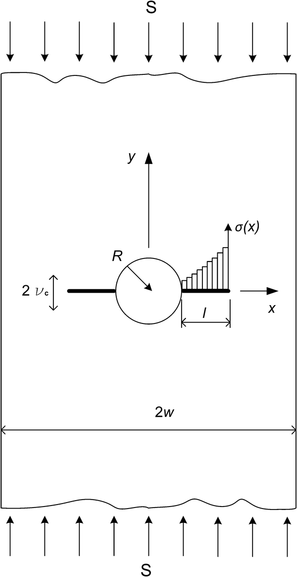
Schematic of Fleck–Soutis model1
Prediction of OHC strength
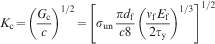
Fibre microbuckling initiates when the local compressive stress parallel
to the 0° fibres at the hole edge is equal to the unnotched stress of
the laminate σun, that is


In order to calculate Kσ as the stress
intensity factor for the equivalent crack due to the local stress, it is needed
to define the relation between the local compressive stress across the microbuckled
layer σ and the axial displacement across the layer 2ν
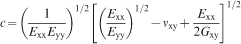
that is represented by the crack closing displacement of the equivalent crack, loaded by the traction σ. As a result of material softening
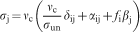
due to damage formation, the local stress is assumed to decrease linearly
with increasing crack normal displacement ν so that the
bridging law σ–ν is linear
(Fig. 12). The area
under the curve σ–ν corresponds
to the fracture energy Gc


Assumed linear bridging law σ–ϵ in microbuckled region
After a few calculations
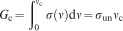
Prediction of fracture energy
The in-plane fracture energy Gc could be estimated using equation (11), after having predicted the critical closing crack displacement νc.
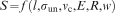
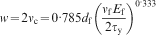
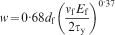
It is assumed (and experimentally showed) that the fibres in the cohesive zone rotate completely and do not lock up so that the linear crack bridging law is appropriate to predict the real behaviour of fibre kinking. The critical crack overlap displacement is found equal to the kink band width w, and it is related to fibre diameter, fibre volume fraction and in-plane shear yield strength in the Budiansky analytical prediction12 and in the empirical Jelf and Fleck equation.17
Budiansky equation12
Prediction of unnotched strength
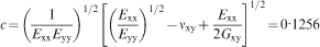
Using the Budiansky fibre kinking theory, the unnotched strength of the unidirectional laminate can be predicted in terms of the shear properties of the composite and the initial fibre misalignment.
As Budiansky showed for an elastic perfectly plastic body

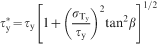
 is the
transverse yield strength of the lamina and β is the
kink band orientation angle. When β = 0, the critical stress σc for a unidirectional
lamina is achieved at φ = 0, and
it results in Argon's11 formula
is the
transverse yield strength of the lamina and β is the
kink band orientation angle. When β = 0, the critical stress σc for a unidirectional
lamina is achieved at φ = 0, and
it results in Argon's11 formula

Results and discussion
The Budiansky–Fleck–Soutis model for the prediction of compressive strength of multidirectional composite laminates was applied to CFRP laminates. Furthermore, the model has been applied to the sandwich panels, assuming that the material systems under investigation are expected to fail via fibre microbuckling. As previously explained, in order to predict the OHC strength, the unnotched compressive strength and the in-plane fracture toughness should be known.
The unnotched strength has been experimentally measured (Table 4), and the fracture toughness has been predicted analytically by means of Budiansky equation (17) and equation (11).
Considering the fibre properties, the laminae mechanical properties, the
matrix yield shear stress and the measured strength σun, the fracture toughness can be determined as
Both values are very close, as would be expected, confirming that Kc associated with fibre microbuckling is a laminate property, and in the analysis that follows, the value of Kc = 33 MPa m1/2 will be used for the OHC strength prediction for the monolithic laminate and the Syncore sandwich panel.
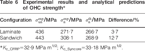
Table 6 shows the results in terms of predicted and experimental OHC strength results.
Experimental results and analytical predictions of OHC strength*
 /MPa
/MPa /MPa
/MPa /MPa
/MPa*Kc_CFRP = 32·9 MPa m1/2; Kc_Syncore = 33·18 MPa m1/2.
Experimental results indicate that, for sandwich panels, even if fibre microbuckling seems to be the critical failure mechanism in compression, other failure modes, such as debonding between face sheets and the foam core, might lead to a premature failure. This should be taken into account in evaluating the possibility of applying the analytical model to sandwich panels. Evaluation of the unnotched strength of the Syncore sandwich panel is underestimated as buckling phenomena in some unnotched Syncore specimens take place, leading to a lower compressive failure load. The unnotched strength of the Syncore sandwich panel reported in Table 4 as the mean of compressive strengths of each specimen needs to be recalculated considering instability aspects; a better evaluation of the real mechanical strength of this material in compression should be performed, neglecting the values measured for A1_2 and A1_5.
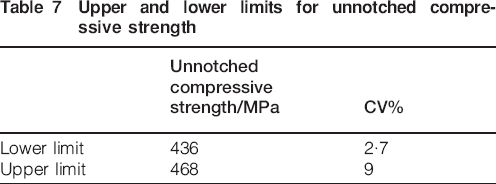
Furthermore, as the compressive response of Syncore sandwich panels is face sheet dependent, the compressive strength of this material is to be ascribed only to the face sheet mechanical behaviour (CFRP face sheets). Indeed, due to their lay-up and number of plies, CFRP monolithic laminates and Syncore panels are expected to have the same value of compressive strength as an intrinsic property of the CFRP. As observed in Fig. 3, the presence of the syntactic core gives better stability to the sandwich panel and less out of plane buckling that may occur in the thinner monolithic laminate. Therefore, it is possible to identify a range of compressive strength values for the CFRP system under study, where monolithic laminate unnotched strength represents the lower limit, and an upper limit is identified as the mean of sandwich unnotched strength performed by unbuckled specimens, as shown in Table 7.
Upper and lower limits for unnotched compressive strength
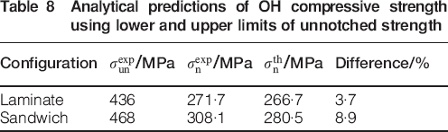
Reconsidering the results from experimental tests, a better evaluation
of the Syncore unnotched compressive strength should be performed considering
the unnotched strength in Table
7. The new values of fracture toughness and unnotched compressive strength
are Kc_sandwich = 34·18
MPa m1/2 and
 = 280·5
MPa, with a difference percentage from the experimental data of <9%
(Table 8).
= 280·5
MPa, with a difference percentage from the experimental data of <9%
(Table 8).
Analytical predictions of OH compressive strength using lower and upper limits of unnotched strength
 /MPa
/MPa /MPa
/MPa /MPa
/MPaIn previous works, it has been observed that fibre microbuckling is the main failure mode for this kind of laminates under uniaxial compression, but in the present work, no microscopy has been performed on the specimens during the compressive tests, and the microbuckling failure mode has not been experimentally observed. However, the overall failure shown in Fig. 9 suggested that damage is localised, initiates at the edge of the hole and propagates across the specimen width, almost perpendicular to the loading axis. Other failure modes are observed in those images in Fig. 6 but are considered as post-failure damage. The analytical prediction results are in good agreement with experimental tests, supporting the validity of the assumption that OH compressive failure is due to localised fibre microbuckling.
Conclusions
Experimental tests were performed in monolithic quasi-isotropic laminates and sandwich panels with a syntactic foam core and CFRP face sheets in order to obtain their unnotched and OHC strengths. Specimen geometries and preparation, load alignment and quality of specimens were taken into account as important factors that influence the measurements. In particular, the presence of flaws and imperfections in the interface between Syncore and CFRP face sheets led to debonding and premature failure in compressive loading. In these cases, buckling phenomena of the single face sheets were observed, and so the compressive strength had a lower value. In general though, the sandwich panels showed better stability than the monolithic laminate and hence a higher overall unnotched compressive strength.
Moreover, experimental and analytical results have shown that unnotched and OHC strengths as well as fracture toughness are intrinsic properties of the specific CFRP laminate system, so the different results from laminate and the sandwich configurations should be ascribed to the different mechanical behaviours of these configurations (manufacturing imperfections, defects) but still could be considered as lower and upper limit values of the specific CFRP system. It should be noted that Euler buckling is difficult to be eliminated completely, and the unnotched strength obtained by the quasi-isotropic monolithic laminate may represent a lower bound value. Higher values are obtained from the sandwich tests, where the core provided better lateral support to the composite skins.
The theoretical compressive strengths for both types of specimens containing through holes are then reasonably predicted by the linear softening cohesive zone model. As the experimental unnotched strength is an influencing input parameter for the analytical model, particular attention is paid in the analysis of experimental results in terms of unnotched compressive strength.
Additional work is required with the aim to monitor the initiation and growth of fibre microbuckling and delamination non-destructively using advanced structural health monitoring techniques.28
Nevertheless, the experimental results are in good agreement with the analytical predictions made by the Budiansky–Soutis–Fleck cohesive zone model.
Footnotes
Acknowledgements
The authors acknowledge the support for this work from Alenia Aeronautica S.p.A. and express thanks to C. Foglio and G. Scarola for their help and useful discussions.
This paper is part of a special issue on Deformation and fracture of polymers and their composites