
Abstract
This paper presents the in-plane shear moduli of three-dimensionally (3D) woven angle interlock composites with different proportions of through the thickness binder content. The in-plane shear modulus Gxy was determined via three techniques: the plate twist test, the V notched beam Iosipescu (ASTM D 5379) and the V notched rail shear (ASTM D 7078) test. The results indicate that the plate twist method is suitable for the measurement of in-plane shear modulus for different 3D weave architectures with large repeat unit cells, and that the measurement is more representative of the global material response.
Introduction
Weaving technology is increasingly being used to produce dry multilayered preforms that are subsequently infused with a liquid matrix material to produce high performance composites. Three-dimensionally (3D) woven composites, in particular, have been shown to possess many advantages compared to traditional performing methods with the ability to tailor fibre placement in the X, Y and Z axis directions.1–3 Manufacturing and performance advantages have been discussed extensively in the literature,3–8 for example, improvements in compression after impact strength compared with two-dimensional (2D) laminated composites and the ability to produce ‘near net shape’ preforms. Subsequently, various authors have developed a range of modelling tools, for example, to predict the geometry of the unit cell,7, 9–12elastic stiffness13–16 and failure strength.17–19
Mechanical testing standards for fibre reinforced polymer (FRP) composites are not universally accepted and understood for 3D woven composites. Standard test methods, however, are employed to 3D woven composites, and some test standards are applicable. For instance, uniaxial testing standards (BS and ASTM methods) for FRP composites have been used widely to determine the uniaxial strength and modulus of 3D woven composite materials.14, 20–22
It is apparent from the body of testing work that has been carried out on 3D woven composites that it is of utmost importance that the sample dimensions encapsulate a representative portion of the actual weave architecture (unit cell). This becomes particularly important for the determination of shear performance. Weissenbach23 examined the issue of testing 3D woven composites and focused on the experimental and theoretical determinations of shear properties. Weissenbach reviewed a number of shear testing methods including short beam shear, Iosipescu, rail shear and off-axis tension. The suitability of the respective methods was critically assessed with regards to their ability to capture a representative response of the weave architecture in the 3D woven composite. The plate twist method was selected for the determination of in-plane shear modulus. The use of the plate twist method is attractive because it did not require the use of strain gauges. In addition, the global material response is represented with this test technique, which would indicate that it is more suitable for testing the materials discussed in this work (unit cell size, approximately 30×50 mm through the full thickness of the laminate compared with >10 mm in Weissenbach23). In a review paper by Tan et al., 24 the authors reported from a numerical study by Whitney and Chou25on 3D woven angle interlock composite, who found the in-plane properties to be very sensitive to changes in fibre volume fraction (FVF). Therefore, local measurements of shear properties using the standard test for in-plane shear measurement such as the V notched Iosipescu26may not be suitable of determining the shear modulus of 3D woven composites27 considering that there are local variations in FVF across the repeat of the unit cell, for instance, resin rich areas where the binder travels through the thickness. As such, the location where the sample is cut from the larger test panel becomes important and would have an influence in the test result, namely, resin rich region between V notches.
Experimental
The measurement of in-plane shear modulus of the 3D woven composites was determined via the modified plate twist method28carried out at the Engineering Composites Research Centre (University of Ulster).
The original test was developed for shear testing wood based structural panels and later standardised for FRP composites.29The test involves a plate sample that is supported exactly at two corners while applying a compressive force at the other opposing two corners, where measurement of the midpoint deflection must be made. Sims et al.29 proposed a modified and simplified approach compared to the original standard. The authors cited that the main difficulty with the original approach was the placement of the loading points that had to be exactly at the corners of the plate, which in practice is difficult to facilitate. However, the formula to calculate the in-plane shear modulus assumed that the plate was loaded/supported exactly at the corners, and as such, even small deviations generated error in the calculation. Sims et al.29 shifted the load points further in, the amount by which was determined by a shifting factor. The shifting factor is simply the reduction of the span L to the span S.
The dimensions and orientations of the composite plate samples are as indicated in Fig. 1. The square plate samples were cut such that the warp X and weft Y directions were parallel to the sides of the plate. Square samples (150±1·5 mm) were cut from larger composite plaques named AI/02 and AI/03 using a diamond tipped saw and the sides ground down parallel to size with a horizontal grinding machine. The composite plate samples are set in between four rollers, as illustrated in Fig. 1.
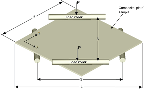
Arrangement of composite plate sample for plate twist test
The manufactured plaques called AI/02 and AI/03 are 3D woven carbon fibre laminates, and the exact details regarding their weave architecture have been reported previously by Buchanan et al.7 Figure 2illustrates schematically the spatial orientation and arrangement of the stuffer, filler and binder tows of the 3D woven composite plaques. These weave architectures were designed in order to investigate the effects of different binder tow sizes (3 and 6 k) relative to the in-plane reinforcing tows in the warp in weft directions (24 and 48 k), which dominate the structure. Further research analysis on these weave architectures investigating modelling, damage evolution during weaving, impact damage and fibre optic sensing is available in the literature.
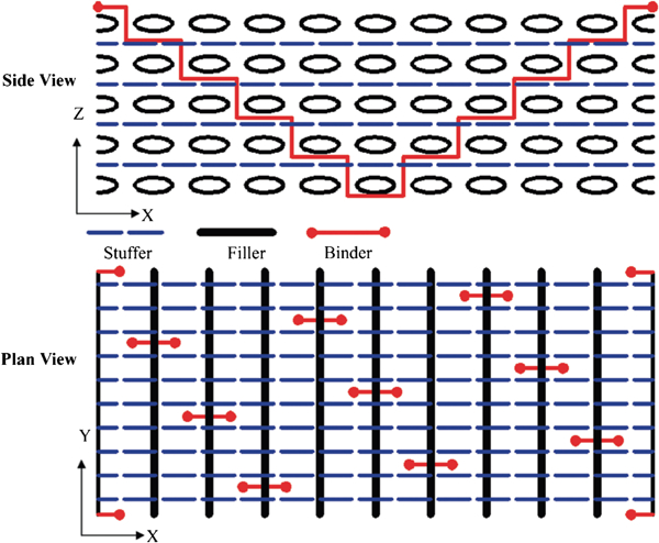
Representation of weave architecture of AI/02 and AI/037
The principal difference in AI/02 and AI/03 was the binder tow content, which was 3 and 6 vol.-% respectively.
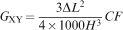
The thickness variation of the composite panels was measured via a grid system. Large variations in thickness were not subsequently found, which is important as the thickness expression in the calculation of shear modulus is raised by a power of 3 (equation (4)).
The plate samples were oriented on a four-point flexural testing fixture
with loading span L and supporting span S
distances set according to the shift factor SF

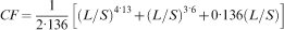
To account for the inboard shift of the contact points in the in-plane
shear modulus calculation, a correction factor CF was incorporated.
The CF has been reported in various publications by Sims et
al.29 (equation (2)), Gommers et
al.30 and Weissenbach et
al.23, 27 (equation (3))

The test was conducted with a 100 N load cell at a test speed of 0·5 mm min−1, and the deflection was recorded via the displacement at the loading points. The deflection was limited to half the measured thickness of the sample. This was because it has been found previously by Sims et al.29 that deflections passed the thickness of the plate, resulting in non-linear behaviour.
Then, the in-plane modulus was calculated according to Weissenbach et
al.23, 27 (equation (4))
The Iosipescu26 and V notched rail shear31 tests were carried out by BAE Systems, UK. The samples for both tests were cut using a water jet cutting machine, and then one surface of the samples was prepared with a high contrast random speckle pattern between the notches.
The Iosipescu test employs a rectangular sample with centrally located V shaped notches measuring 76·3×19·1 mm and 12 mm between the notches. The samples were tested in a specially made test fixture from ‘Wyoming Test Fixtures Inc.’, in which one side is held securely while the other side can displace as the load is applied to the edges of the sample. Uniform shear strain is considered to occur between the centrally located V notches. Each sample was loaded at 1 mm min−1 while recording the load and strain measured by gauges located in between the V shaped notches and digital image correlation (DIC).
The rail shear test utilises a V notched sample with increased width compared to that of the Iosipescu V notched sample. The larger specimen (76·3×57·5 and 31 mm between notches) increases the area of strain field measurement between the notches compared with the Iosipescu sample.
The samples were mounted in the V notched rail shear testing fixture from ‘Wyoming Test Fixtures Inc.’ The fixture was mounted in an Instron 4507 test machine (200 kN load cell) and loaded at a rate of 1 mm min−1while recording the force, displacement and strain measured by gauges located in between the V shaped notches and DIC.
A disadvantage with the Iosipescu method is the concentration of load transmitted at the edges of the sample that can result in crushing in materials with high shear moduli. A benefit of the V notched rail shear is that the load transmitted through the face of the sample, as such eliminating the edge crushing problem.
Results and discussion
Table 1 compares the shear modulus measured via the plate twist test for the various 3D woven laminates and the results obtained from the Iosipescu test26 and the V notched rail shear method.31
Average shear modulus of 3D woven angle interlock composites
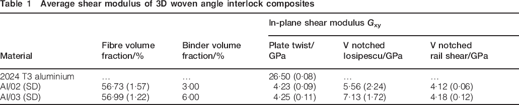
The plate twist test was carried out on T3 aluminium samples in order to verify that the test was set up and carried out correctly. The plate twist method induces very small loads that were at the bottom range of the 100 N load cell used to carry out the test. As such, any misalignment of test fixture and fittings could lead to an erroneous result. The results for the 3D woven angle interlock composites containing 3% (AI/02) and 6% (AI/03) binder tow contents differ very slightly. Essentially, the weave design/architecture is the same for both types; only the binder content changes. The increase in binder content leads to a slight increase in fibre volume fraction. The increase in fibre volume fraction may account for the slightly higher shear modulus obtained for AI/03. Figure 3 indicates that the binder in this weave is split between approximately vertical parts (contributing to the through the thickness FVF) and horizontal parts (contributing to the in-plane FVF in the warp direction). The standard deviation for the plate twist test for both laminates is low.
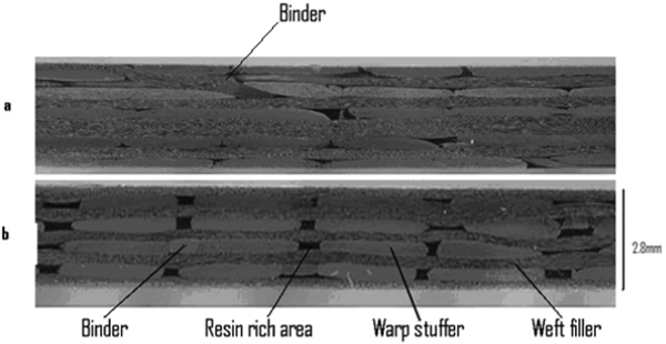
Micrographs of actual composite weave architecture
The strain recorded for the V notched Iosipescu and rail shear techniques used both strain gauges and DIC. The strain gauges give a single point of measurement compared to the DIC that shows a full field picture. Comparison of the extracted strain recorded by each technique showed good agreement and confidence in the DIC system for the accurate measurement of strain. The local measure provided by these test techniques is in contrast to the plate twist test in which the global material response is measured and only requires force and deflection data.
The Iosipescu test implements a V notched beam that has a small test section (12×1 mm). The Iosipescu measured values for both laminate types are, on average, 50% more than that determined by the plate twist and V notched rail shear tests. The results are also not consistent as indicated by the standard deviations for the results on both laminate types compared with the plate twist and rail shear methods. This may be explained by the local measurement of shear strain and the location of the strain gauge on each sample.
The larger V notched sample utilised in the rail shear test produces results that are close to the plate twist results. Figure 4 illustrates the strain map of the V notched Iosipescu (left) and the V notched rail shear (right). The rail shear sample clearly produces a larger area of uniform strain compared with the Iosipescu sample. Consequently, the results obtained from the V notched rail shear method are more consistent than those from the V notched Iosipescu test. Therefore, measurement for 3D woven composites with local variations in FVF would suggest that encapsulating a larger/global measurement would be more representative.
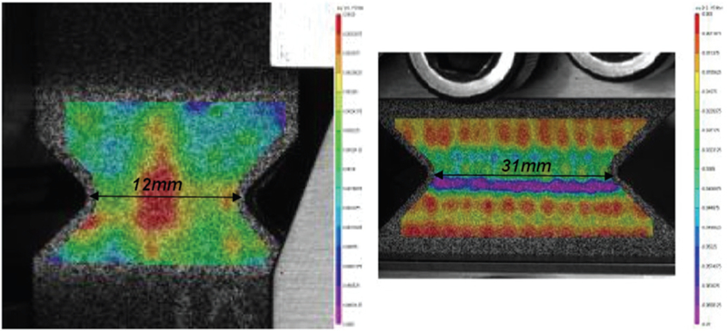
Comparison of shear strain field between V notched Iosipescu (left) and rail shear (right) test specimens
Conclusions
The most consistent results were obtained via the plate twist test and V notched rail shear method. The plate twist test has the advantage of being non-destructive and does not require strain gauges or any DIC system but is limited to measuring shear modulus. The V notched rail shear method has a larger area for measurement of the shear strain field than the V notched Iosipescu and produces more consistent shear modulus results at par with the plate twist and can also measure the shear strength. The V notched Iosipescu results were all higher and possessed higher variation compared with both of the other test techniques. The V notched Iosipescu test has the ability to determine shear strength and modulus. However, it could not be recommended for testing 3D woven composites with large repeat unit cells. In the instance that only shear modulus is required, then the relatively straightforward plate twist test would be advantageous, and if shear strength is also required, then the more involved V notched rail shear technique would be suitable.
Footnotes
Acknowledgements
This work was supported by the 3DSIMCOMS consortium in collaboration with the Technology Strategy Board.
This paper is part of a special issue on Deformation and fracture of polymers and their composites