
Abstract
A novel conductive polymer composite (CPC) based on carbon nanotube (CNT) and binary polymer blend of low density polyethylene (LDPE) and ultrahigh molecular weight polyethylene (UHMWPE) was successfully fabricated by high speed mechanical mixing and hot pressing. The conductive CNT/LDPE component was only dispersed on the surfaces of UHMWPE particles, manifesting combined segregated and double percolated structure. The temperature resistivity behaviour of the CPC was investigated in this paper. A typical double positive temperature coefficient (PTC) of resistivity was observed near the melting points of LDPE and UHMWPE followed by a negative temperature coefficient (NTC) of resistivity. The resistivity began to rise at the maximum crystallisation temperature during cooling, indicating that the conducting nanoparticles were expelled from the crystalline phase. This CPC also exhibited a relatively low PTC and NTC effect, which was determined by the combined segregated and double percolated conductive network as well as high viscosity of UHMWPE matrix. Moreover, with the assistance of in situ optical micrograph and transmission electron microscopy, we found that the subtle microstructural evolution of the conductive network via Brownian motion and crystallisation induced flow was responsible for the higher room temperature resistivity.
Keywords
Introduction
The positive temperature coefficient (PTC) and negative temperature coefficient (NTC) of resistivity are two major physical phenomena of electrical conductive particle [e.g. carbon black (CB),1–5 carbon nanotube (CNT)6–11 and graphene sheet12] filled conductive polymer composites (CPCs). Enormous studies have been focused on the PTC and NTC effect of CPCs due to their potential applications such as switching sensors, self-regulating heaters and shielding structures.13–16 The PTC and NTC phenomena are the abrupt increase and the succeeding gradual decrease in the resistivity of CPC around the melting point of the matrix polymer respectively. Up to now, many mechanisms, including volume expansion, conduction pathway theory and tunnelling effect theory, have been put forward to interpret the PTC effect.17–20 For the NTC of resistivity, the universal viewpoint is that it resulted from the formation of flocculated structure when the viscosity of polymer is sufficiently low at elevated high temperatures.21 However, the mechanisms about the PTC or NTC effect are still in dispute because too many parameters can affect temperature resistivity behaviours in very complex manners, including the properties of conductive fillers, the features of polymers, the microstructures of composites and the test conditions.21 Bai et al. found that the oxyfluorinated CNTs have marked effects on PTC/NTC characteristics of a CNT/high density polyethylene (HDPE) composite, and concluded that oxyfluoration of conductive fillers was a good means to attenuating NTC intensity in a CNT/HDPE composite.9 Luo et al. investigated the influence of crystallisation process and crystallinity of polymer matrix on the PTC characteristics of a CB/polyethylene (PE) composite and found that the annealing treatment can effectively improved PTC intensity of the composite.22
Nevertheless, to our knowledge, the majority of works about the temperature resistivity behaviours were mainly based on a homogeneous three-dimensional conductive network, in which large amounts of conductive fillers were added to form well developed conductive paths. Namely, these PTC materials have the disadvantage of high conductive filler loadings at the insulator/conductor transition, resulting in complex processing, inferior mechanical properties and manufacturing costs. Therefore, it is of importance for academic and industrial research groups to develop a high performance PTC material with a low conduction threshold.
The formation of segregated structure in CPCs has been one of the most successful strategies for achieving an ultralow percolation threshold; in such a structure, conductive fillers are located only at the interfaces between the polymer matrix particles, instead of being randomly distributed throughout the whole system.23 Zhang et al. utilised the segregated conduction mechanism in CB/ultrahigh molecular weight polyethylene (UHMWPE) composite to fabricate a new PTC material with a very low percolation threshold (∼2 wt-%CB), and they proposed that the well developed CB segregated conducting paths can eliminate the NTC effect even at temperatures much higher than the melting point of UHMWPE.6 The formation of double percolation structure is another way to lower the conduction percolation of CPCs, in which conducting particles are selectively located in just one phase of a binary polymer blend to form a complicated conductive network.24 Xu et al. fabricated CB/polypropylene/polyvinylidene fluoride ternary composites with double percolated structure, and they found that the composite demonstrated a low percolation threshold (∼2 vol.-%CB) and a pronounced PTC effect. These results were ascribed to the selective dispersion of CB particles in polypropylene and the consecutive volume expansion of the co-continuous phases.24
Recently, we reported a novel percolation mechanism in CNT/polyethylene composites with the combined segregated and double percolated structure, in which CNTs formed conducting channels in polyethylene and the percolated CNT/polyethylene component constructed the continuous conductive layers in the interfaces between UHMWPE granules.25 This CPC material showed an ultralow percolation threshold (0·049 vol.-%). Now, a unique conductive architecture combined with segregated and double percolated structure exists in this composite, which offers a good opportunity to explore the relationship between microstructure and variations of temperature resistivity behaviours. Thus, the aim of this article is directed to elucidating the origin of the PTC/NTC effects of CNT/low density polyethylene (LDPE)/UHMWPE composites.
Experimental
Materials and sample preparation
The main materials used in this study include CNT, LDPE and UHMWPE. Ultrahigh molecular weight polyethylene was from Beijing No. 2 Auxiliary Agent Factory (Beijing, China). Low density polyethylene (grade LD450) was from Beijing Yanshan Petrochemical Corp. (Beijing, China). Carbon nanotubes (20–40 nm diameter and 10–20 μm length) were kindly supplied by Chengdu Organic Chemicals Co. Ltd (Chengdu, China). Xylene [analytical reagent (AR) grade] and alcohol (AR grade) were purchased from Chengdu Kelong Chemical Reagent Factory (Chengdu, China) and were used as received. The solution dispersion process was used to prepare CNT/LDPE composites with a CNT content of 20 wt-%. First, CNT powder (2·0 g) was added to ethanol (400 mL). Ultrasonic oscillation (for 20 min) and mechanical stirring (at room temperature, for 1 h) were then used to disperse the CNTs. At the same time, 8 g of LDPE was completely dissolved in 240 mL of xylene; this was carried out at 130°C for 2 h. The stable CNT/alcohol suspension was then quickly dropped into the xylene/LDPE solution. The mixture was flocculated using ethanol and was then filtered and dried in a vacuum oven for 48 h at 60°C. After that, CNT/LDPE and UHMWPE powders were mixed in their solid state in a mechanical high speed mixer for 4 min at a speed of 25 000 rev min−1. Finally, the powder was pressed in a hot press for 5 min, under 10 MPa, at a temperature of 200°C, to form films.
Method and testing
The sample, a 50 μm thick film, was used for optical microscopy (OM) observations at a heating and cooling rate of 2°C min−1. Scanning electron microscopy (SEM) was performed using a field emission SEM (Inspect-F, FEI, Finland), with an accelerating voltage of 20 kV. Transmission electron microscopy (TEM) was performed on an FEI Tecnai F20, with an accelerating voltage of 200 kV. The thickness of the sample films was 80 nm, as determined using a Leica EMUC6/FC6 microtome. In the resistivity temperature test, the copper electrodes were attached to the cross-sections of a sample in the parallel direction with silver paint. The sample was immersed in silicone oil of a temperature controlled apparatus to avoid oxidation. The thermal procedure of the samples for resistivity temperature test was heated from 20 to 180°C at 2°C min−1 and held at this temperature for 3 min, then cooled to 20°C at the same rate. The data were recorded by a computer. Thermal analyses were carried out by a TA Q200 differential scanning calorimeter (DSC). The samples were heated to 180°C at 2°C min−1, kept for 3 min and then cooled at 2°C min−1 to 20°C, a heating–cooling journey matching the resistivity temperature test.
Results and discussion
In order to thoroughly understand their origin of the temperature resistivity behaviours, it is necessary to summarise the typical morphology of the specific segregated and double percolated structure of CNT/LDPE/UHMWPE composites first. The primary feature of the CPC is that the conducting CNT/LDPE layers, rather than CNTs alone, only distributed at the thin interfaces of the neighboring UHMWPE granules and construct a novel segregated and double percolated conducting architecture.25 The OM observation of CNT/LDPE/UHMWPE composites with a CNT content of 0·25vol.-% was carried out (Fig. 1a). This OM image clearly shows a typical segregated conductive network, in which the CNT based conductive channels surrounded the UHMWPE particles throughout the CPC. More detailed microstructure information can be obtained from SEM and TEM images, as shown in Fig. 1b. The UHMWPE particles exhibit a faceted structure. Adjacent individual polyhedron-like UHMWPE grains form very thin interfaces and contain all the percolated CNT/LDPE blends, also thus indicating the formation of double percolated structure (the inset of Fig. 1b). Therefore, using a small amount of LDPE as the carrier polymer of CNTs and the selective distribution of the percolated CNT/LDPE blend between the interfaces of UHMWPE granules, a new conduction mechanism containing the perfect segregated and double percolated conductive network takes effect, giving rise to an ultralow CNT concentration (Fig. 1c).25
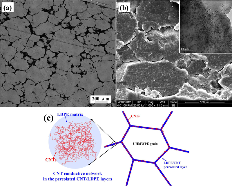
a OM and b SEM) images of fractured surface of CNT filled composites with CNT content of 0·25 vol.-% and c schematic of cell-like conductive network formation in CNT/LDPE/UHMWPE composites: inset of b shows high magnification TEM image. Figure 1 will be reproduced in mono for the printed version
Figure 2 depicts the temperature resistivity behaviours of CNT/LDPE/UHMWPE composites during three heating and cooling runs (HCRs). In this work, the CNT loading of CPC is fixed at 0·25 and 0·4 vol.-%, both just beyond its percolation threshold to make the conductive network highly sensitive to the temperature field, and make resistivity temperature behaviours of these two composites comparable (in addition, if the CNT content of CPC is below 0·25 vol.-%, the volume resistivity is too high to be recorded). Although the amount of LDPE is extremely low (2·0 and 3·2 wt-%), two obvious resistivity jumps can be observed around Tm of LDPE and UHMWPE during the first HCR (Fig. 2a) because of the specific segregated and double percolated conductive network. As the ambient temperature increases, the first resistivity jump from ∼1·2×10−7 Ω cm to the maximum value of ∼3·5×10−7 Ω cm occurs at ∼110°C, which is just Tm of LDPE. With further increasing temperature to ∼125°C, a slight decrease in resistivity is observed, which is referred to as an NTC effect. This NTC effect is attributed to the reagglomerates of CNTs, due to the lower viscosity above Tm of LDPE. When the temperature reaches Tm of UHMWPE, the second resistivity jump occurs. Namely, the resistivity experiences an abrupt increase from 3·5×10−7 Ω cm at 130°C to 1·2×10−8 Ω cm at 138°C. Followed by the second resistivity jump, the CPC demonstrates a pronounced NTC behaviour, in which the resistivity of composites decreases from 1·2×10−8 Ω cm at 138°C to 2·3×10−6 Ω cm at 180°C. During cooling from 180°C, the resistivity starts to rise at 123°C, and an indistinctive NTC effect follows after the maximum resistivity at 118°C, resulting from the breakdown of conductive network induced by matrix crystallisation.
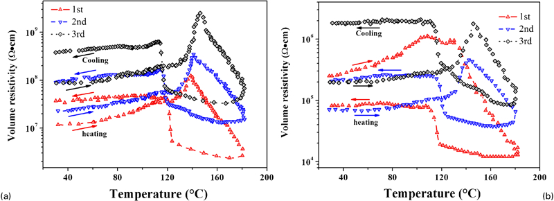
Resistivity temperature behaviours of a 0·25 vol.-% and b 0·4 vol.-%CNT filled composites in HCR
To evaluate the PTC and NTC effects quantitatively, the intensity of PTC and NTC can be defined as follows: IPTC = log(RP/RTR) and INTC = log(Rmax/Rk), where RP is the maximum resistivity in heating journey, RTR is the original resistivity at room temperature, Rmax is the maximum resistivity in the whole heating process and Rk is the resistivity at 180°C. The CPCs with 0·4 vol.-%CNT loading possess the same value of IPTC (0·65) for the first resistivity jump with that of the second one (Fig. 2b). Compared to sample with 0·25 vol.-%CNT content, the PTC effect near 110°C is stronger, especially in the first HCR. Other temperature resistivity relationship of 0·4 vol.-%CNT sample is similar with those of 0·25 vol.-%CNT one. Figure 3 displays the DSC scans of 0·25 and 0·4 vol.-%CNT filled CPCs during HCR. Apparently, the PTC and NTC effects of CNT/LDPE/UHMWPE composites during HCRs are in good agreement with the melting and crystallisation behaviours estimated from DSC curves, which show that Tm and the maximal crystallisation temperature Tc of composites are ∼134 and 122°C respectively. However, because of the extremely low content of LDPE (2·0 and 3·2 wt-%), there are no obvious melting and crystallisation peaks of LDPE in the DSC curves.
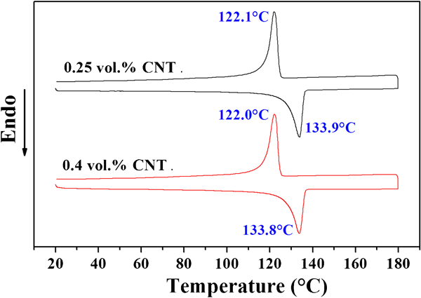
DSC scans of 0·25 and 0·4 vol.-%CNT filled composites at heating and cooling rates of 2°C min−1
In order to further reveal the origin of temperature resistivity behaviours in CNT/LDPE/UHMWPE composites, we employed in situ OM to examine the morphology evolution for the CPCs during HCRs (Figs. 4 and 5). In the original samples, the CNT/LDPE conducting layers in the interfaces between UHMWPE particles form a well developed and cell-like conductive network (Figs. 4a and 5a). With the increase in temperature, the interparticle distance between CNTs in the conductive CNT/LDPE layers gradually increases due to the different thermal expansion coefficient of CNT and LDPE (Figs. 4b and 5b). Around the melting temperature of LDPE, ∼110°C, the melting of crystallites results in a dramatic increase in the volume of the composite. Thermal expansion causes severe separation of previously contacted conductive CNTs, and thus, the conducting paths in the CPC becomes defective, corresponding to the first sharp increase in resistivity. In addition, the resistivity of composites is more sensitive to temperature field at high amounts of CNT/LDPE component, resulting in higher IPTC for the first PTC effect of 0·4 vol.-%CNT filled composites.
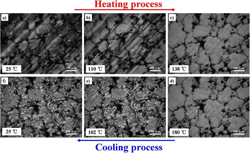
Images (OM) of 0·25 vol.-%CNT filled composites in first cycles at heating and cooling rates of 2°C min−1
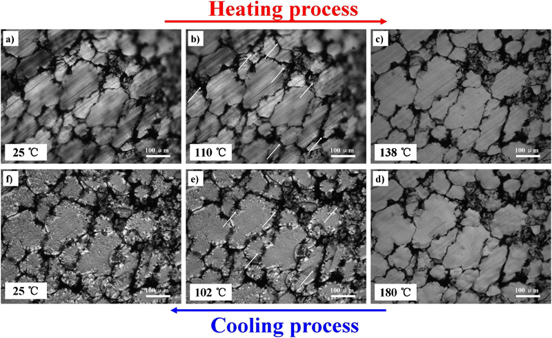
Images (OM) of 0·4 vol.-%CNT filled composites in first cycles at heating and cooling rates of 2°C min−1
With temperature further increasing, the conducting channels between UHMWPE granules become gradually damaged due to the larger expansion coefficient of UHMWPE matrix. Although the reaggregates of CNTs in CNT/LDPE component can help the formation of the conductive CNT pathways, there is not an obvious NTC effect followed by the first PTC phenomenon, only manifesting a platform of the resistivity from 110 to 130°C. When temperature rises to ∼138°C, the destruction of conductive network exceeds the reformation of conducting paths ( Figure 4 Figs. 4c and 5c), namely, the second PTC effect around the UHMWPE melting point takes place.
Because it is difficult for CNTs to migrate from LDPE matrix to the UHMWPE particles due to the high melt viscosity of UHMWPE, they only diffused partly along the interfaces between LDPE and UHMWPE. IPTC of CNT/LDPE/UHMWPE CPCs at 0·25 and 0·4 vol.-%CNT is relatively low (below 1·5) compared to other PTC/NTC materials.26–28 During the three HCRs, the values of IPTC increase from 1·01 to 1·47 for 0·25 vol.-%CNT sample and from 0·65 to 1·02 for 0·4 vol.-%CNT filled CPC. Similarly, the peak temperatures of the main PTC effects also rise to >8°C with increasing the run number. Particularly for CPCs with 0·4 vol.-%CNT loading, the mechanism of the PTC effect is changed from the destruction of the conductive network in CNT/LDPE blend at the first HCR to the breakdown of the CNT conducting channels between the interfaces of UHMWPE particles at the second procedure (Figs. 4c and 5c).12 Thus, the temperature for the PTC effect experiences a dramatic increase from 108 to 142°C, as shown in Fig. 6. As shown in Figs. 4d and 5d, the conductive architectures of this system survive from the environment of the high temperature at 180°C.
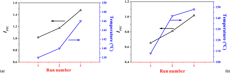
Variation of IPTC and PTC temperature versus run number for composites with a 0·25 vol.-% and b 0·4 vol.-%CNT concentration
The NTC effect occurs when CNTs start to reagglomerate on the surfaces of UHMWPE grains to form additional conductive channels in the polymer melt. Noticeably, INTC is larger than IPTC, owing to the low melt viscosity of LDPE, which is in favour for the reorganisation of conducting paths, especially at 0·4 vol.-%CNT filled CPCs. With temperature dropping from 180°C, the resistivity increases slowly due to cooling procedure inducing the higher viscosity of samples, which hinders CNTs from agglomerating to construct the conductive CNT network. As the CPC is cooled to Tc of polyethylene matrix, CNTs are ejected from the crystalline phase and only remain in the amorphous phase, and for the meantime, they locally flowed along with the crystallising melt due to crystallisation induced flow (Figs. 4e and 5e).12 The volume fraction of CNTs in the interfacial region is further diluted. The conductive path is thus gradually broken up, which can also be observed from Figs. 4f and 5f, resulting in an increase in the room temperature resistivity.
For this segregated and double percolated CPCs, the room temperature resistivity at 0·4 vol.-%CNT content becomes lower than the initial resistivity after returning to room temperature in the first HCR. This phenomenon can be attributed to the addition of LDPE as the carrier polymer of CNTs, which offers the matrix with the low melt viscosity and temperature for the reagglomeration of CNTs to form additional conducting paths. However, after the three HCRs, the room temperature resistivity becomes a little larger than the initial resistivity. This is because the initial and final state of CNT/LDPE/UHMWPE composites is a little different from each other. The OM images in Fig. 7 display the conductive networks of the original samples and the ones after the three HCRs at 0·25 and 0·4 vol.-%CNT loading. Compared with the original sample (Fig. 7a and c), the density of the conducting paths in the CPC after the three HCRs (Fig. 7b and d) is clearly reduced because of the agglomeration of CNT conductive channels and the diffusion of CNTs into the UHMWPE matrix induced by crystallisation flow.12
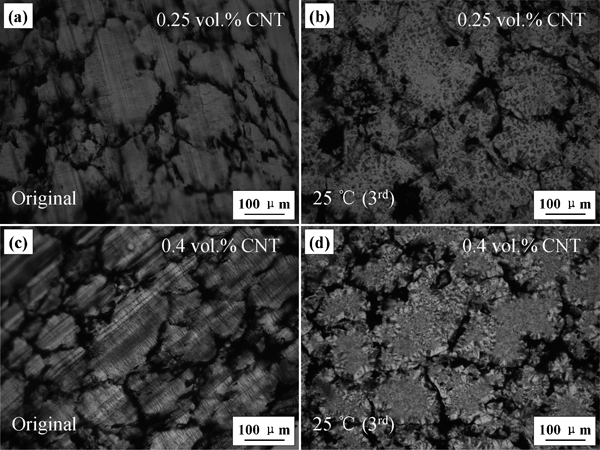
Images (OM) of original samples with a 0·25 vol.-% and c 0·4 vol.-%CNT content and samples after three HCRs with b 0·25 vol.-% and d 0·4 vol.-%CNT loading
TEM was also used to observe the details of the structures in CNT/LDPE/UHMWPE composites. Figure 8a provides more detailed information on single conductive pathways, in which the UHMWPE particles have effectively squeezed CNT/LDPE component into the relatively long conductive channels. For the samples after three HCRs, due to the intense Brownian motion and crystallisation induced flow, the conductive CNT/LDPE layer of the sample is much thicker than the original layer, and the CNTs in the conductive layer are less densely packed compared to those of the original samples (Fig. 8b). Moreover, the conductive network with the combined segregated and double percolated structure may be weaker than the homogeneous three-dimensional conductive network, so it is difficult to recover to the original condition, leading to a higher resistivity.
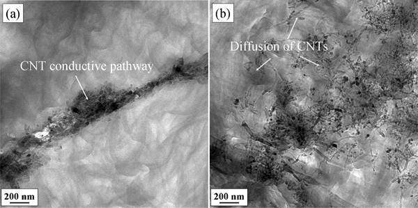
Images (TEM) of a original samples and b CPCs after three HCRs: content of CNT is 0·25 vol.-%
Conclusions
In summary, the CPCs with segregated and double percolated structure manifest a typical double PTC effect, and the PTC and NTC intensities are relatively low. These results can be attributed to the specific conductive network structure and the difference of the melt viscosity and temperature between UHMWPE and LDPE matrix. Further work will be focused on the study of factors influencing the temperature resistivity behaviour of the composite.
Footnotes
Acknowledgements
The project was funded by the National Natural Science Foundation of China (contract nos. 50925311 and 20976112).