
Abstract
Natural rubber (NR) based nanocomposites containing a constant amount (50 phr) of standard furnace carbon black and carbon nanotube (CNT) at a concentration from 1 to 5 phr have been prepared. Their dielectric (dielectric permittivity and dielectric loss) and microwave properties (coefficients of absorption and reflection of the electromagnetic waves and electromagnetic interference shielding effectiveness) have been investigated in the 1–12 GHz frequency range. The results achieved allow recommending CNTs as second filler for NR based composites to afford specific absorbing properties.
Introduction
Since the documented discovery of carbon nanotubes (CNTs) in 1991 by Iijima1 and the realisation of their unique2 physical properties, including mechanical, thermal and electrical, many investigators have endeavoured to produce advanced CNT composite materials that exhibit one or more of these properties. For example, CNT are quite effective as a conductive filler of polymers, compared to traditional carbon black microparticles, primarily due to their high aspect ratios. Recently, the electrical percolation threshold has been reported to be at 0·0025 wt-% of CNT and conductivity at 2 S m−1 at 1·0 wt-% of CNT in epoxy matrixes.3
Owing to their fibrous shape with extremely large aspect ratio, CNT may, at a very low concentration, yield composites of low resistivity, high permittivity and frequency dispersion.4 It is well known that the nanosized particles usually exhibit properties different from those of microsized particles of the same composition, which is the primary reason for the great attention currently paid to the radio and microwave frequency performance of CNT composites. A number of novel CNT features have been reported in the literature.5–11 These results demonstrate the possibility to design CNT composites with electric/dielectric properties, which are more diverse than those obtainable with other carbon fillers.
There are numerous investigations on nanocomposites based on elastomeric matrixes and CNTs as filler, although the researchers’ attention has been directed mainly to the reinforcement of polymer matrixes. The influence of this unique filler upon the dielectric and microwave properties of the elastomeric composites has been scarcely studied. Lately, there have been articles suggesting possible applications of such nanocomposites in microwave absorbers for solving problems of electromagnetic interference (EMI) and electromagnetic compatibility.4,12–20 The polymer matrixes used in these cases are usually epoxy resin, acrylonitrile–butadiene rubber, styrene–butadiene rubber, silicone rubber and polyurethane rubber. Only in the last years have appeared reports on the investigations on natural rubber (NR) based nanocomposites filled with CNTs.21–24
The price of CNTs is still significantly higher than that of standard furnace carbon black. In this context, the aim of this study is to determine whether the addition of small quantities (1–5 phr) of CNT in addition to a standard significantly greater than the amount of active furnace carbon black (50 phr) can be used as a way to modify and improve the dielectric (dielectric permittivity, dielectric loss) and microwave properties [coefficient of reflection, coefficient of attenuation and EMI shielding effectiveness (SE)] of NR based composites in the high frequency range (1–12 GHz). Data for such a study on the reported combination of fillers have not been found in the literature.
Experimental
Characterisation of carbon nanofillers used
Multiwalled CNTs as produced by Hayzen Engineering Co. (Ankara, Turkey) were used in our investigation. The material purity was higher than 95% (density, −150 kg m−3). Carbon nanotubes were with average diameter of about 15 nm and length of 1–10 μm (Fig. 1). The pattern taken in an electron diffraction regime (insert in the right corner) shows the typical polycrystal structure of CNT.
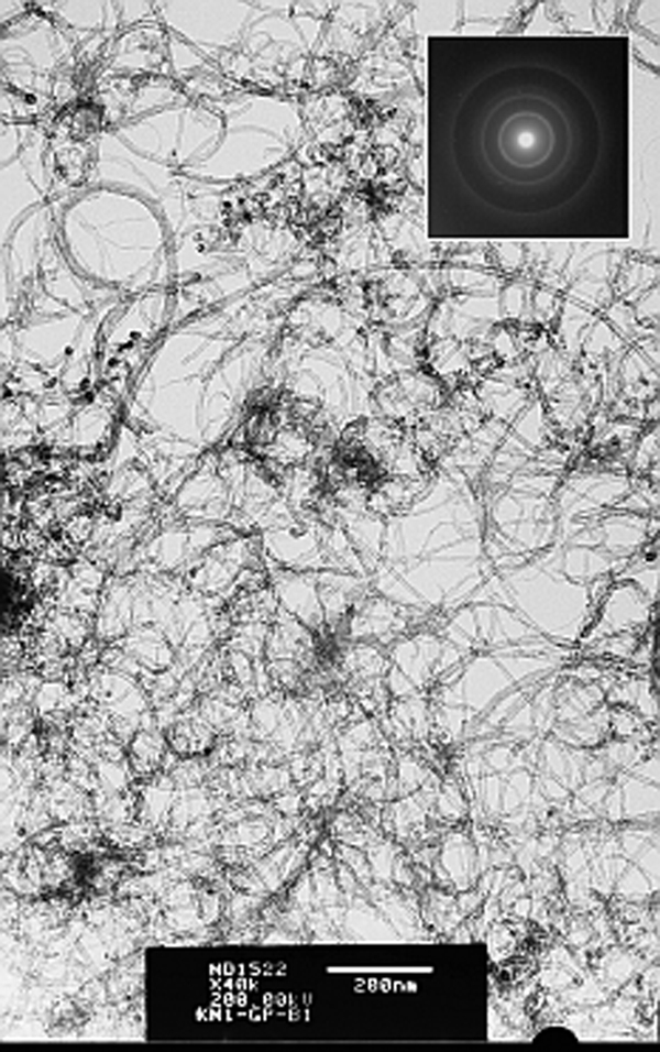
Images (TEM) of CNT in transmission regime and selected area electron diffraction regime (insert in the right corner)
The specific structural features of the carbon black used (Corax N 220, produced by Evonik) are shown in Fig. 2.
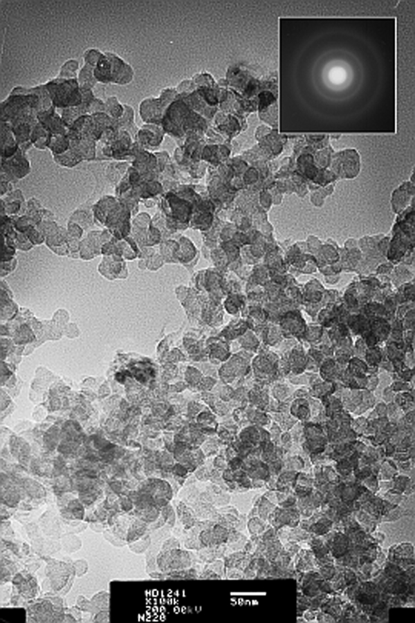
Images (TEM) of furnace carbon black Corax N220 particles together with SAED (insert in the right corner)
As seen, the primary particle size of the carbon black used is ∼20 nm, but their capability of forming secondary aggregates and agglomerates is considerable. SAED indicates the absence of crystal structures.
Natural rubber (SMR 10) was used as a rubber matrix in our investigations. Other ingredients such as zinc oxide (ZnO), stearic acid (SA), N-(1,3-dimethylbuthyl)-N′-phenyl-p-phenylenediamine (Vulkanox 4020, produced by Lanxess), dibenzothiazyl disulphide, MBTS (Vulkacit DM, produced by Lanxess) and sulphur were of commercial grades and used without further purification.
Preparation and vulcanisation of rubber compounds
Table 1 summarises the formulation characteristics of the rubber compounds (in phr) used for the investigations.
Composition of rubber compounds studied
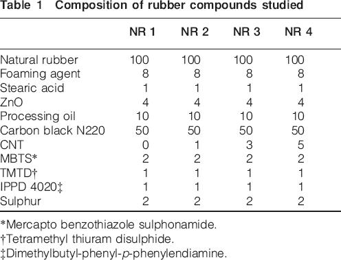
*Mercapto benzothiazole sulphonamide.
†Tetramethyl thiuram disulphide.
‡Dimethylbutyl-phenyl-p-phenylendiamine.
The rubber compounds were prepared on an open two-roll laboratory mill (L/D 320×360 and friction 1·27) by incorporating precharacterised CB and CNTs into an NR matrix at various loadings (Table 1). The speed of the slow roll was 25 min−1. The experiments were repeated for verifying the statistical significance. The ready compounds in the form of sheets stayed 24 h before their vulcanisation.
The optimal vulcanisation time was determined by the vulcanisation isotherms, taken on an oscillating disc vulcameter MDR 2000 (Alpha Technologies) at 150°C according to ISO 3417:2002.
These composites were evaluated for their dielectric (dielectric permittivity, dielectric loss angle tangent) and microwave (reflection coefficient, attenuation coefficient and SE) properties in the 1–12 GHz frequency range.
Measurements
Microwave properties
Reflection and attenuation
Measurements of reflection and attenuation were carried out using the measurement of output (adopted) power Pa in the output of a measuring line without losses, where samples of materials may be included. Because of the wide frequency measurement, a coaxial line was used. Samples of the materials were shaped into discs with an external diameter D = 20·6 mm, equal to the outer diameter of the coaxial line and thickness of Δ≈2 mm. The internal diameter depended on the relative dielectric permittivity of the material.
The sample reflected a part of the incident electromagnetic wave with power Pin. The rest of the wave with power Pp penetrated the material, so that the attenuation L depended on the coefficient of reflection |Γ|. Its module was determined by a reflect meter.
Thus, the attenuation was determined by


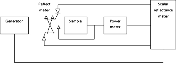
Scheme of equipment for measuring microwave properties
Shielding effectiveness
This parameter is defined as the sum of the reflection losses R (dB) and attenuation L (dB) in the material.
It can be directly measured or calculated from the measured reflectance and attenuation in the material. In the first case, as measured: incident power on the sample Pin and adopted after the sample Pa, SE is determined by


In the present work, the SE was determined by equation (4).
Dielectric properties
Complex permittivity
The determination of complex permittivity was carried out by the resonance method based on the cavity perturbation technique.
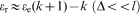
Having measured the resonance frequency of the empty cavity resonator fr, a measurement of the shift in resonance frequency fϵ was carried out in the presence of the sample material. Then, the dielectric constant ϵr was calculated from the shift in resonance frequency, cavity and the sample cross-sections Sr and Sϵ respectively

Loss factor tan δ
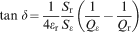
The loss factor tan δ was calculated from the quality factor of the cavity with Qϵ and without sample Qr
The following scheme presents the set used for measuring the dielectric properties (Fig. 4).
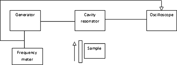
Scheme of equipment for measuring dielectric properties
Results and discussion
Dielectric properties
Complex relative dielectric permittivity: Real part
The dependence of the real part of complex dielectric permittivity (the so called relative dielectric permittivity ϵr) on the frequency and amount of the second filler is shown in Fig. 5.
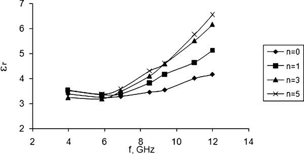
Frequency dependence of relative dielectric permittivity ϵr at constant first filler amount (CB, 50 phr) and various second filler amounts (CNT at n phr)
As seen from the graphs, the values of relative dielectric permittivity increase with the increasing frequency and amount of the second filler (CNT) at a constant amount of carbon black (50 phr). The influence of the frequency and second filler amount is significantly pronounced in the 7–12 GHz range, and the values of ϵr are between 3·2 and 6·5.
The polarisation mechanism operating in the gigahertz frequency range is purely electronic or orientational, with relaxation times shorter than the time period of the applied signals. Interfacial polarisation, which is the basic reason for the dispersion in dielectric permittivity at radio frequency regime, does not affect the microwave frequencies as it does not produce dispersion in ϵr because of its much shorter relaxation time, although ϵr has been found to increase at higher amounts of CNTs in the composite, as shown in Fig. 5. This phenomenon of increased dielectric permittivity at a higher second filler concentration can be attributed to the enhancement of electrical conductivity of the composites.
Complex relative dielectric permittivity: Imaginary part (dielectric loss)
The dependence of the imaginary part of the complex dielectric permittivity (dielectric losses) on the amount of the second filler and the frequency at constant amount of CNT is shown in Fig. 6.
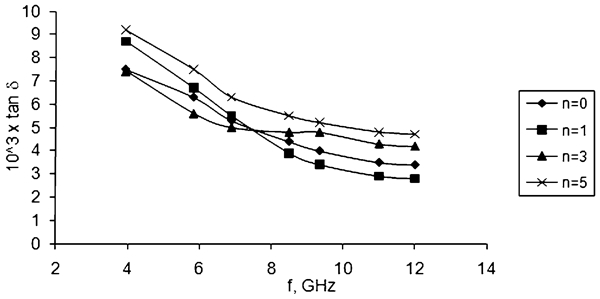
Frequency dependence of dielectric loss at constant first filler amount (50 phr) and various second filler amounts (CNT at n phr)
With the increase in frequency, the dielectric losses decrease smoothly throughout the entire frequency range studied (3×10⁻³–9×10⁻³). The influence of the second filler amount is not so well pronounced.
Microwave properties
Coefficient of reflection
The dependence of the coefficients of reflection of electromagnetic waves on the frequency and amount of the second filler is shown in Fig. 7.
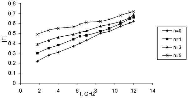
Frequency dependence of reflection coefficient at constant first filler amount (50 phr) and various second filler amounts (CNT at n phr)
The graphs show that with the increase in frequency and second filler amount, the reflection coefficient also increases and reaches a value of 0·7 when n = 5 and f = 12 GHz. The influence of CNT amount is stronger compared to the influence of frequency.
Attenuation coefficient
The dependence of the attenuation coefficient on the amount of the second filler and frequency is shown in Fig. 8.
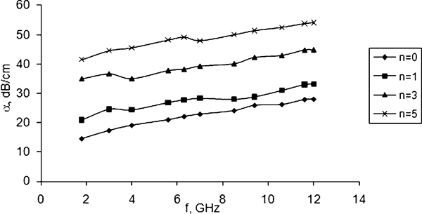
Frequency dependence of attenuation coefficient at constant first filler amount (50 phr) and various second filler amounts (CNT at n phr)
It is obvious that with the increase in the second filler amount and in frequency, the coefficient of attenuation also increases. When the amount of CNT is higher (e.g. at 5 phr), the attenuation coefficient of the composites is in the range of 42–54 dB cm−1.
Shielding effectiveness
The dependence of the SE on the second filler amount and on frequency is shown in Fig. 9. The decrease in SE values depending on frequency is quite obvious since the growth of the coefficient of attenuation is apparently not high enough to compensate the increase in reflection coefficient. According to equation (4), these two coefficients are crucial to the formation of SE value.
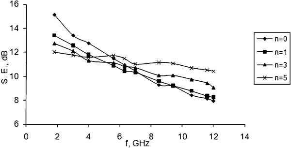
Frequency dependence of EMI SE at constant first filler amount (50 phr) and various second filler amounts (CNT at n phr)
The composite containing 5 phr CNT has the best values of this parameter, which remain within the 11–12 dB for the entire frequency range studied.
It has been found that the percolation threshold for composites comprising the neat investigated fillers is 3 and 15 phr for CNTs and CB respectively.25 That might be due to the fact that the composites have different geometries of CNT and CB (the values of aspect ratio for CB is 1 and for CNTs is from 120 to 200). According to Balberg,26 the average interparticle distance can be different in the carbon nanofillers with different aspect ratios. The more spherical-like the structure, the larger the interparticle distance. For the elongated particles, their composites have a very narrow distribution of the distances due to the entangled particle structures and the volume resistivity of the composites decreases monotonically with increasing the aspect ratio. The interparticle distance, composite microstructure and volume resistivity have a strong influence on the microwave properties.27 Presumably, the increase in the dielectric permittivity of the composites, containing CNT and carbon black, toward high frequencies is induced by the dielectric relaxation, which suggests that the established percolation network structure is not stable and easily affected by the external frequency disturbances.
Our investigations have shown that the addition of small amounts (1–5 phr) of CNT to a standard constant amount of active furnace carbon black can be used as a way to modify and to improve the dielectric (dielectric permittivity, dielectric loss) and microwave properties (coefficient of reflection, coefficient of attenuation, EMI SE) of NR based composites in the high frequency range of 1–12 GHz.
Conclusions
NR based nanocomposites containing a constant amount of standard furnace carbon black and CNT at concentrations from 1 to 5 phr have been prepared. Their dielectric (dielectric permittivity and dielectric loss) and microwave properties (coefficients of absorption and reflection of the electromagnetic waves and EMI SE) have been investigated in the of 1–12 GHz frequency range. The effect of CNT upon the properties of the composites has been evaluated. Adding small amounts of CNTs to a constant amount of carbon black, one can control and primarily improve the dielectric and microwave properties of composites based on NR in the high frequency range 1–12 GHz. The results achieved allow recommending CNTs as a second filler for NR based composites to afford specific absorbing properties.
Footnotes
Acknowledgements
The present research is a result of an international collaboration program between the University of Tabuk, Tabuk, Kingdom of Saudi Arabia, and the University of Chemical Technology and Metallurgy, Sofia, Bulgaria. The authors acknowledge gratefully the financial support from the University of Tabuk.