
Abstract
Integrating rechargeable battery cells with fibre reinforced polymer matrix composites is a promising technology to enable composite structures to concurrently carry load and store electric energy, thus significantly reducing weight at the system level. To develop a design criterion for structural battery composites, rechargeable lithium polymer battery cells were embedded into carbon fibre/epoxy matrix composite laminates, which were then subjected to tensile, flexural and compressive loading. The electric charging/discharging properties were measured at varying levels of applied loads. The results showed that degradation in battery performance, such as voltage and energy storage capacity, correlated well with the applied strain under three different loading conditions. Under compressive loading, battery cells, due to their multilayer construction, were unable to prevent buckling of composite face sheets due to the low lateral stiffness, leading to lower compressive strength than sandwich panels with foam core.
Keywords
Introduction
Rechargeable batteries made of polymer electrolytes have better mechanical flexibility and stiffness than conventional electrochemical rechargeable batteries. These new polymer batteries provide designers more freedom in creating flexible structures with energy storage capability, such as wearable electronics. One important application is the integration of rechargeable polymer batteries into composite structures, 1 creating a multifunctional material system with the capability to perform several functions simultaneously or sequentially in time.2, 3 The main objective of multifunctional structures is to improve the system's performance by integrating different physical properties of the subsystem constituents. 4 In the case of energy storage systems, traditional electrochemical batteries are heavy, bulky and concentrated (in terms of the spatial location for vehicles), which have adverse effects on the driving range, storage space and dynamic handling of vehicles. In contrast, thin lithium polymer battery cells can be embedded into lightweight fibre reinforced polymer matrix composites to carry mechanical loads as well as store electrical energy, enabling significant weight reduction at the system level, with less redundancy and improved system level performance.5–7 Currently, these types of structures are being investigated in applications ranging from unmanned air vehicles and unmanned underwater vehicles to electric cars. 8
Recent research has led to improved understanding of the integration effect on both the structural and electrical functions of structural batteries.9, 10 Thomas et al.2, 11, 12 fabricated sandwich composite laminates embedded with thin polymer battery cells and examined their flexural response and Ragone curves (the relation between energy density and power density or the relation between specific energy and specific power). Their work demonstrated the feasibility of integrating lithium ion cells into structural composites to provide energy storage capability (50 W h L−1) without degrading structural performance and buoyancy that were specifically targeted at marine applications. Pereira et al.13, 14 prepared structural battery composites with very thin solid state lithium ion energy cells (0·1 mm thick), capable of withstanding both the temperature and pressure required for autoclave manufacture at 120°C. Their results indicated that the performance of solid state thin film lithium energy cells remained unchanged when subjected to tensile loads as high as 50% of the tensile strength of the carbon fibre composite and uniaxial pressure up to 2·0 MPa. 15 Ning et al. 16 investigated the capacity fade by repeated rapid charging/discharging of a lithium ion battery (Sony US 18650) at 1C, 2C and 3C rates (which indicates transfer of all of the stored energy in 1 h, half an hour, and 20 min respectively). After 300 cycles of charging/discharging, the capacity loss was 9·5, 13·2 and 16·9% respectively. 16 Li et al. 17 reported that the discharge capacity of a commercial Li ion battery (Sanyo UF 653467) faded rapidly when cycling at 1C rate. In particular, the capacity decreased from 1005 to 700 mAh after 286 cycles. Studies of XRD, TEM, and SEM on the individual electrodes indicated that the capacity fade was linked to cation disorder and microcracks of the LiCoO2 particles in the cathode, as well as the thickening of passive film on the anode. 17
The main finding of the aforementioned research is that the electrical performance of structural composite batteries depends strongly on the level and mode of mechanical loading (flexural loading seems to have less detrimental effect than tensile loading). However, the relation between mechanical deformation and changes in electrical performance, which is of great importance to the design and optimisation of structural batteries, is not clear. To this end, this paper presents an investigation of the effects of mechanical deformation on a polymer rechargeable battery's electrical performance (internal resistance and energy storage capacity) under tension, bending and compression loading. Based on these new results, a failure criterion was formulated for designing flexible polymer battery structures.
Materials and methods
Materials and specimen preparation
Three types of specimens were manufactured: monolithic laminates, composite sandwich panels with foam core and composite batteries with lithium polymer cells as the core. For each specimen type, three coupons were manufactured for mechanical and electrical testing.
The monolithic carbon fibre composite laminates were fabricated by a wet lay-up process using Sigmatex carbon 2/2 twill weave fabrics (T300, 3K tow, 199 GSM) and the West System epoxy 105 with slow hardener 206. Composite laminates (composed of eight plies of carbon fabric) were cured at room temperature for 24 h, resulting in a cured thickness of 3 mm.
Composite sandwich laminates with foam core were made by bonding of two cured composite laminate face sheets with a core made of Corecell A80 plain SAN closed cell foam using the Araldite 420 A/B adhesive, referring to Fig. 1a. Each face sheet consisted of four plies of carbon fabric with a cured thickness of 1·5 mm. These sandwich panels, without battery cells, were referred as the control specimens.
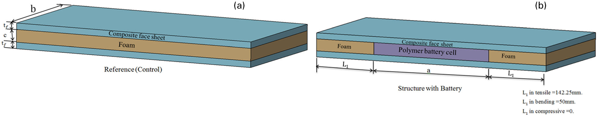
Configurations of both a composite sandwich control specimen and b structural battery composite
Structural batteries were manufactured by replacing the foam core with a Kokam USA rechargeable lithium polymer cells (type SLPB 356495 with the dimension of 95·5×64·5×3·5 mm), as illustrated in Fig. 1b. The battery cell was bonded to the composite face sheets using the Araldite 420 A/B adhesive. In this case, the battery cell doubles as a structural element as well as an energy storage device. Isolated electric wires, 30 mm long and 3 mm thick, were soldered to the battery's electrodes to act as leads for electric charging and discharging.
The lithium rechargeable battery cell employed in this investigation has an operation temperature range from −20 to 60°C. Charging and discharging tests were conducted by constant current and constant voltage methods. The battery cells, weighing 44 g and featuring an energy storage capacity of 2100 mA h, have the minimum voltage of 3 V, a nominal voltage of 3·7 V and the maximum charging voltage of 4·2 V. The corresponding peak charge and discharge current is 4·2 A.
Experimental
Tension and compression tests were conducted on the monolithic composite laminate samples to characterise the mechanical properties of the composite materials. To avoid buckling failure, compression tests were carried out using the NASA short block compression fixture. The specimen dimensions were 380·0×64·5×3 mm for tensile tests, and 49×25×3 mm for compression tests. Three specimens were tested for each loading condition.
Both the control sandwich specimens (without batteries) and the composite batteries were tested under tension and three-point bending in accordance with ASTM standards D3039-7 18 and D790. 19 The compression tests were carried out using an antibuckling fixture as shown in Fig. 2. The specimen dimensions were 380·0×64·5×6·5 mm for tensile tests, 195·5×64·5×6·5 mm for flexural tests and 95·5×64·5×6·5 mm for compression tests. The span length of three-point bending tests was 100 mm. The control sandwich specimens were first tested to determine their ultimate failure loads under tension, compression and bending.
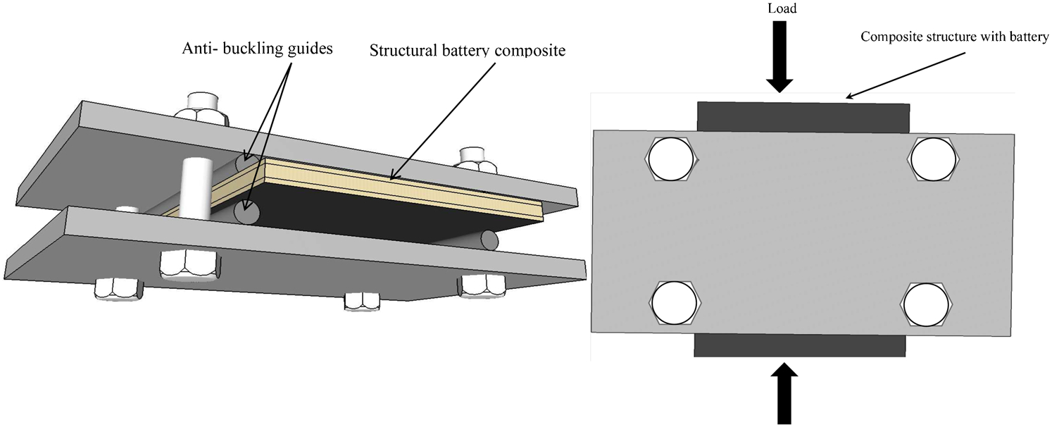
Antibuckling guide fixture for compression tests
The structural batteries were charged and discharged by the Cellpro PowerLab 6 multichemistry battery workstation to determine the baseline electrical performance in the absence of any mechanical deformation. Parameters such as voltage, current, internal resistance and energy storage capacity were measured. Composite batteries were then subjected to tension and compression at a load increment of ∼25% of the ultimate failure loads of the control specimens. For bending tests, the load increment was 20% of the ultimate flexural strength of the control sandwich specimens under bending. A crosshead speed of 1 mm min−1 was employed for all three modes of loading. After each loading step, the specimens were unloaded, and charging and discharging were carried out to quantify the electrical performance of the structural battery composites.
According to the manufacturer's recommendations, the Li ion batteries employed in the present investigation can undergo 500 cycles of charge–discharge at 1C rate (at 20°C). Our tests confirmed that these batteries exhibited no detectable degradation in performance after 10 charge–discharge cycles at 1C and 2C rates. Since all composite batteries employed in this work would experience no more than five charge–discharge cycles at 1C and 2C rates, any degradation in the electric performance of the composite batteries would be due to the application of mechanical loading.
To characterise the electrical performance of the batteries, the maximum current and voltage recommended by the manufacturer were measured after the composite battery specimens were subjected to different levels of mechanical loads. The composite battery specimens were charged at a constant current of 4 A. During charging, the voltage increased from 3 to 4·2 V, when charging was terminated. In the discharging mode, the current was maintained constant at 4 A, with discharging being terminated when voltage dropped from 4·2 to 3 V.
Experimental results and discussion
For monolithic composite laminates, the typical stress–strain curves under tension and compression are shown in Fig. 3. The average failure load was 69·3 kN for tension tests and 20·5 kN for compression tests. The average failure stress of the composite samples was 358 MPa under tension and 273 MPa under compression respectively. The average Young's modulus of the composite laminate was 33·3 GPa under tension and 34·3 GPa under compression.
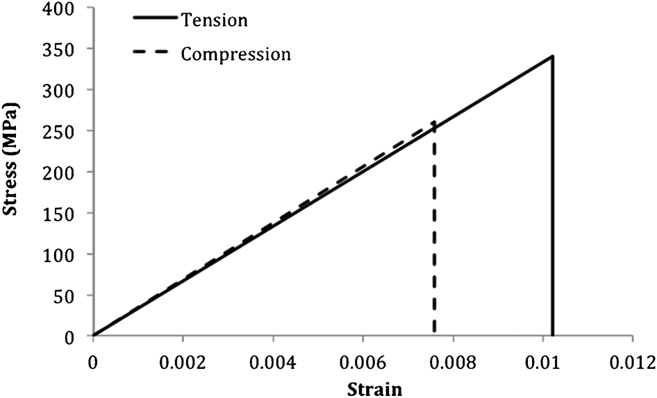
Typical stress–strain curves of monolithic composite laminates under tension and compression
Figure 4 presents a comparison of mechanical strength of composite sandwich with foam core (control specimens) and battery core. The structural battery composite (SBC) specimens achieved the same maximum strength as the control specimens under both tension and bending. The average tensile failure load was 52 kN for both the control and SBC specimens, corresponding to an effective tensile stress of 268 MPa in the composite face sheets. Compared with the monolithic composite laminates, sandwich panels reached lower strength due to the extra stress concentration near the grips caused by the low stiffness of the foam core.
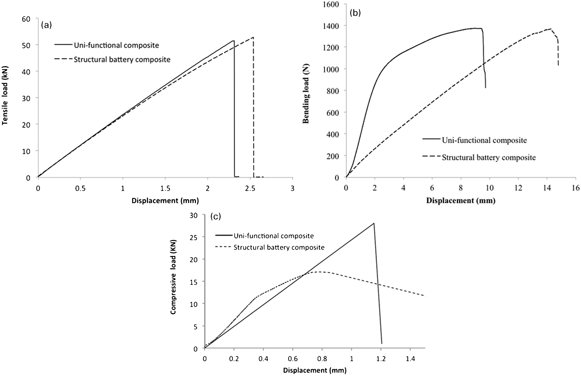
a tension; b three-point bending; c compression
Under compression, the foam core sandwich specimens reached an average failure load of 30 kN. This load corresponds with a compressive stress of 155 MPa, which is substantially lower than the compressive strength of the monolithic composite laminate (which equals to 260 MPa). The possible reason for the lower compressive strength of the foam core sandwich structure is that the limited through thickness stiffness of the foam core was insufficient to prevent buckling of the face sheets.
By comparison, the composite battery specimens reached only half of the ultimate compressive strength of the control specimens. The average failure load was 17 kN, corresponding with a stress of 87·8 MPa in the face sheets. The reason for much lower compressive strength, as compared to the control specimens under compression, is that the composite face sheets over the battery region were not fully supported against buckling. The battery cells consisted of 17 folded layers, and these layers were not mechanically connected. Under compressive loading, the face sheets over the region of the battery cell would behave as two separate laminates, without the support of a bonded core. Consequently, the laminate would buckle under compression. The buckling stress can be estimated by assuming the face sheets are uncoupled (not bonded together)
20
Since tensile loading was applied to the structural battery specimens at an increment of ∼25% of the ultimate failure load of the control specimens, these specimens were subjected to gradually increasing tensile loads of 12, 25, 37 and 48 kN. After each load increment, the specimens were unloaded to measure the electrical performance by charging and discharging the embedded battery cells. Under bending load, the structural battery specimens were subjected to gradually increasing flexural loads of 20% of the ultimate bending strength of the control specimens. Therefore, the battery performance was characterised after flexural loads reached 274, 548, 822, 1230 and 1356 N respectively. In the case of compressive loading, a load increment of ∼25% of the control specimens’ compression strength was employed. Owing to premature buckling failure under compression, the electric performance of structural batteries was characterised after subjecting to two load levels: 7·5 and 15 kN. Figure 5 presents the images of the typical fractured specimens under tensile, bending and compressive loading respectively. The tensile specimens fractured outside the region where the battery cell was embedded, while the bending specimens failed in the middle of the specimen (and the battery cell), near the location of the top roller.
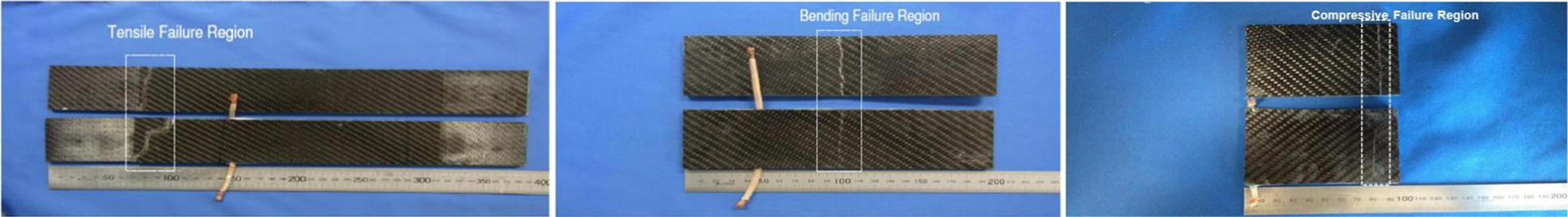
Photos of fractured composite sandwich specimens (without copper wires) and structure battery composites (with copper wires) subjected to tensile, flexural and compressive loading
Figures 6–8 show the charging and discharging current versus time for stand alone battery and SBC specimens subjected to tensile, bending and compressive loads. The pertinent voltage variations are presented in Fig. 9. It can be seen that the application of mechanical loads has reduced the charging and discharging time, indicating the reduction in capacity. In general, the embedded battery cells could be charged and discharged upon the application of the mechanical loads, even after the complete failure of the SBCs.
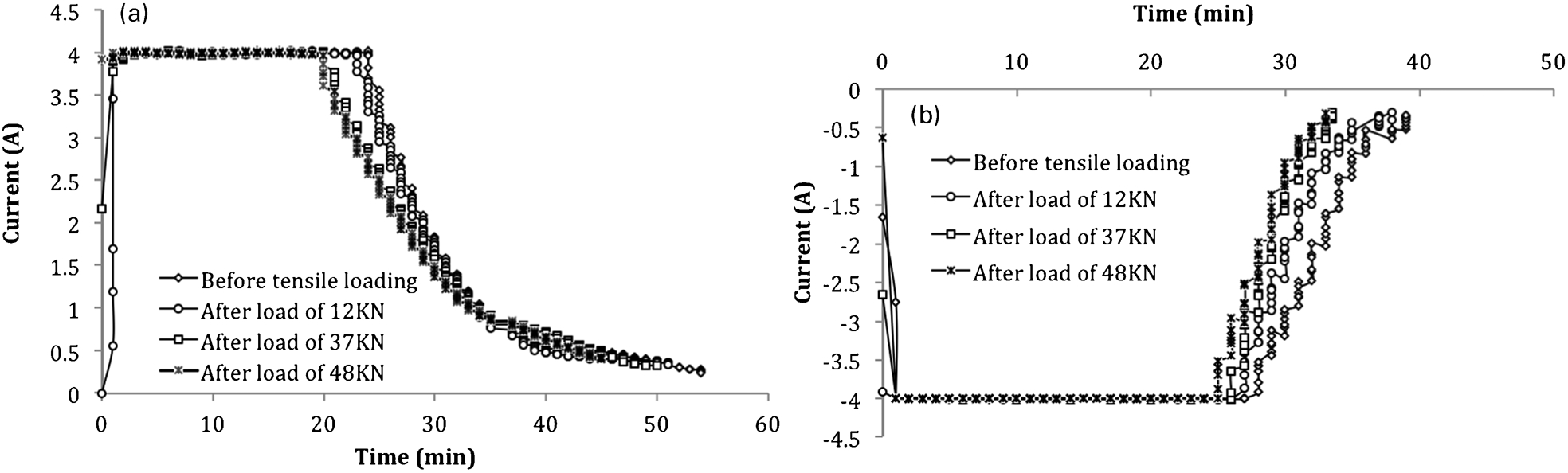
a charging and b discharging current as function of time before and after application of tensile loads
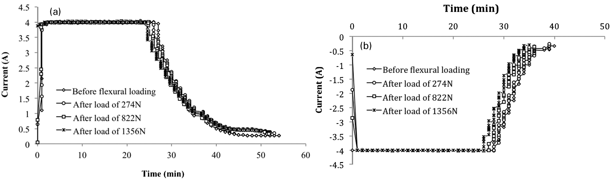
a charging and b discharging current as function of time before and after application of flexural loads
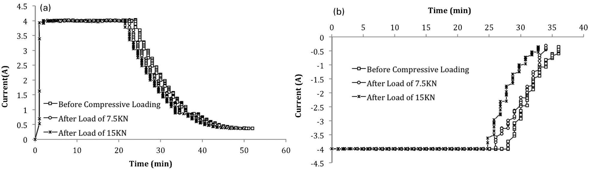
a charging and b discharging current as function of time before and after application of compressive loads
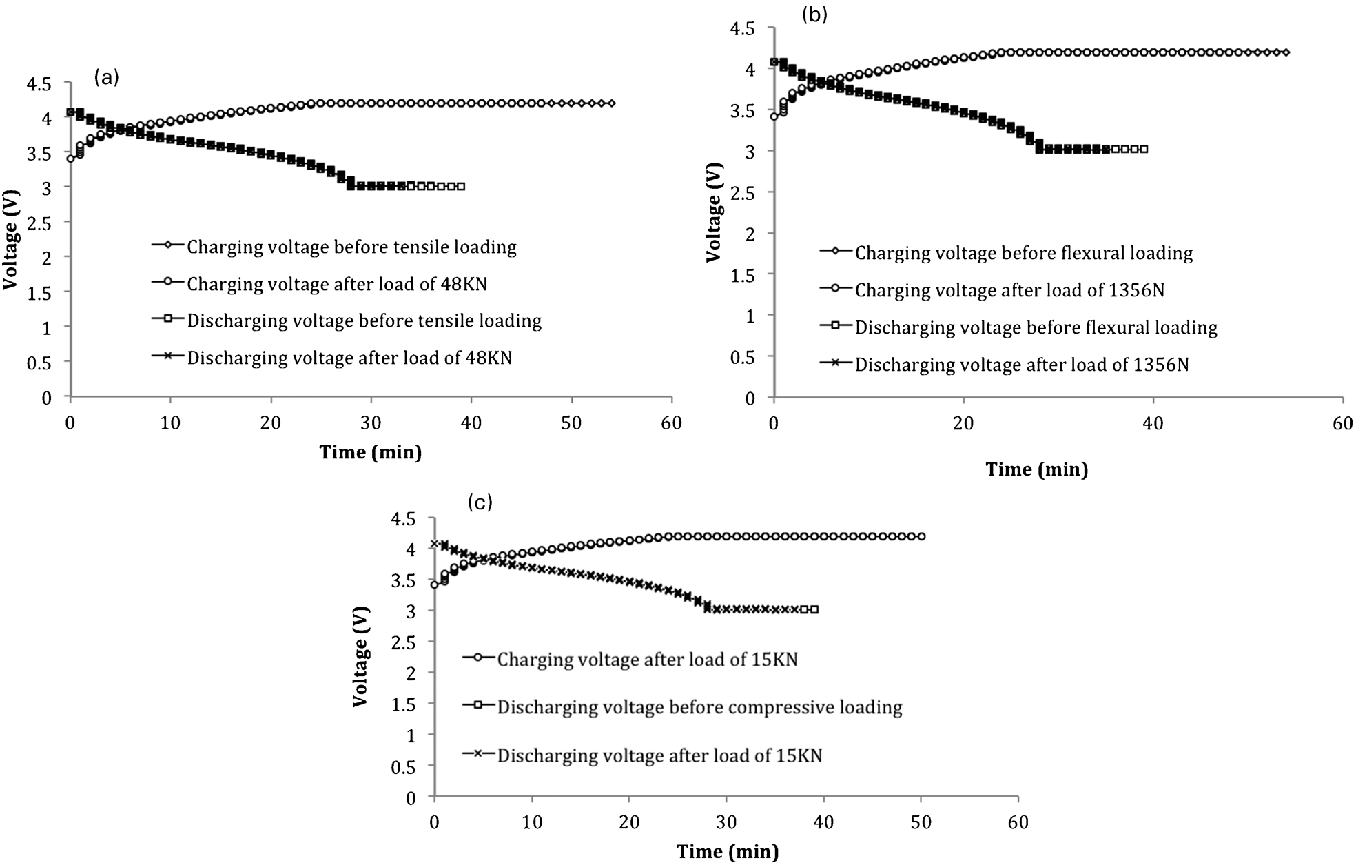
Charging and discharging voltage before and after application of a tensile, b flexural and c compressive loading
With these results, it is possible to determine the batteries’ electric energy storage capacities C, defined as
 , where i is the charging and discharging current, and τ is the charging and discharging time. The change in energy storage capacity was <5 after 60% of bending failure load, and 50% of tensile and compressive failure loads were applied. After the application of higher mechanical loads, greater degradation in electrical performance occurred, especially in the case of tensile loading. Greater reduction in the energy storage capacity was observed for tensile tests than that pertinent to bending tests, which was accompanied by a greater increase in the internal electrical resistance under tensile loading than the other two loading modes. Since the embedded battery was able to maintain the maximum energy storage capacity during mechanical loads, i.e. the time for charging and discharging did not change significantly after the SBC specimens were subjected to different mechanical loads, i.e. they are considered as close to fully functional.
Figure 10 shows the correlation between the percentage of changes in battery's capacity (ΔC/C0) and in the internal resistance (ΔR/R0) after being subjected to tensile, bending and compressive loading. It is interesting to note that the reduction in battery's charging and discharging capacity, after being subjected to tensile, bending and compressive deformation, correlates well with the changes in the internal resistance. Consequently, resistance can be used as a good indicator for detecting degradation in a battery's performance.
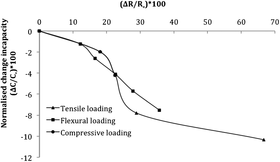
Correlation between capacity reductions with increases of internal resistance under three modes of loading
A strain based failure criterion
Results presented in the previous section indicate that mechanical loads can affect the energy storage capacity of battery cells, with the level of reduction depending on the applied load. To design and optimise structural batteries to achieve load carrying and energy storage requirements, it is necessary to identify a scaling relationship or failure criterion that can relate changes in battery storage capacity to the applied mechanical loads.
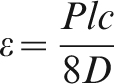
From the measured applied load, the tensile and compressive strains were calculated using the following relation
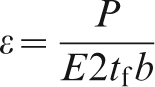
Under flexural loading, the maximum flexural strain of the battery was determined using sandwich laminate theory,
21
ignoring the stiffness of the core, in accordance with to the following equation
 . Consequently, the peak compressive strain is
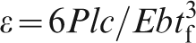
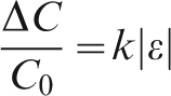
Figure 11 shows the changes in energy capacity (ΔC/C0) versus the mechanical strain under tensile, bending and compressive loads. The results reveal that changes in storage capacity are approximately proportional to the applied strain. A linear regression of the experimental results yields
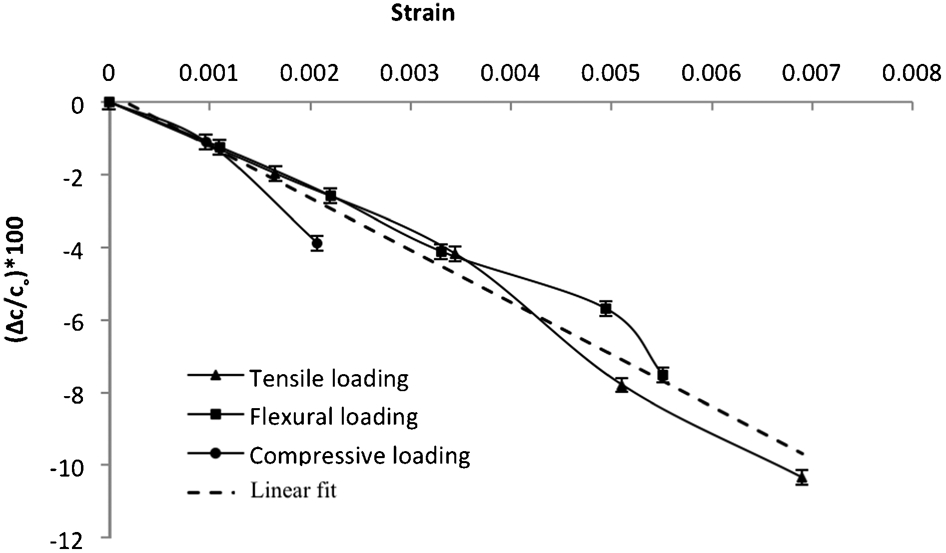
Percentage of capacity changes caused by mechanical deformation
The precise mechanisms responsible for the observed increase in internal resistance and reduction in energy capacity of the structural batteries are very complex, with many contributing factors. Recent studies have identified that one possible cause is the viscoelastic creep of the porous separator in lithium ion batteries. 22 Changes in the pore structure, in particular, the pore closure, may reduce the efficiency of ion transport, increasing the internal resistance and reducing capacity. These physical changes do support the present finding that the mechanical strain is a promising correlating parameter for battery performance under mechanical loading. This new failure criterion for structural batteries provides an important tool for designing flexible energy storage devices incorporating polymer batteries.
Comparing the performance of the structural battery under tensile, compressive and bending loads, it is clear that bonding of the battery cells to the composite laminates did not make significant difference to the tensile and compressive properties, due to the low modulus of the battery cells. Furthermore, the incorporation of the battery cells only marginally improved the bending rigidity and strength under bending loading. If the battery cells were not bonded to the laminates, they would not experience any mechanical strain; hence, no degradation in electrical properties would occur.
Conclusions
The multifunctional performance of structural batteries has been investigated by subjecting composite sandwich structures embedded with polymer lithium ion battery cells to mechanical loading and electric charging and discharging. Three different mechanical loadings were investigated, including tension, compression and bending. The results show that embedding lithium polymer batteries into composite sandwich structure did not significantly alter the mechanical properties under tensile and flexural loading, but caused premature buckling failure during compression as compared to sandwich structures without battery cells. Degradation in batteries' charging and discharging capacity has been found to correlate strongly with the increase in the internal electrical resistance and mechanical strain experienced by the battery cells. This scaling relationship provides a design criterion for structure battery composites.