
Abstract
The effect of side stream channel height on flow stability in 30° coextrusion geometries was investigated. The studies were conducted on a Dow LD150R low density polyethylene melt using a single extruder to feed a flow cell in which the delivered melt stream was split before, and rejoined after, a divider plate in a slit die. Wave type interfacial instability occurred at critical stream thickness ratios. Reducing the side stream channel height broadened the layer ratio operating range before the onset of interfacial instability, therefore improving process stability. Stress fields were quantified and used to validate principal stress differences of numerically modelled flow. Stress field features promoting interfacial instability in each of the die geometries were identified. Interfacial instability resulted when the stress gradient across the interface was asymmetric and accompanied by a non-monotonic decay in the stress along the interface from its inception.
Introduction
Coextruding stratified layers of polymer melts are a complex process. Indeed, in polymer coextrusion processes, melt streams are constrained not only by metal die walls but also by at least one moving boundary in the form of stream interfaces. The complexity is further magnified when the moving interface is formed between melts with different thermal and strain history dependent viscoelastic properties. Streamline curvature tends also to vary in a complex manner at regions of confluence, which leads to subtle changes in process history.
Indeed, it is not unusual for this type of flow to give rise to interfacial instability. Interfacial instability is an unsteady state process in which the interface position between layers varies spatially in a transient manner and usually leads to non-uniform layer thickness in an extruded product. The interface disturbance may not necessarily propagate to the surface of extrudate; its presence can simply be an internal pattern of parabolic form. Nonetheless, the presence of interfacial instability often has deleterious effects on the physical, mechanical or optical properties of the extruded product.
There is a long standing desire to understand the driving mechanism(s) for interfacial instability. There have been several experimental and theoretical approaches involving one-dimensional, fully developed coextrusion flows.1–9 Early experimental work 1–5 often proposed empirical rules based on viscous and elastic properties or stream thickness ratios for multilayer flows of polymer melts with distinctly different rheological properties. More theoretical approaches involving complex two-dimensional finite element method (FEM) required considerable computation.10–24 Zatloukal et al.16–24 modelled the experimental studies of Perdikoulias et al.8, 9 and theoretical analysis by Vlcek et al. 10 to explore the origin of interfacial instability. They utilised simplified viscoelastic stress calculations, which took account of flow history as well as both shear and extensional rheological behaviour. In particular, non-isothermal, flow history dependent viscoelastic stresses were calculated for flow fields in a film blowing annular coextrusion die using a modified eight-mode Leonov constitutive equation and FEM. The modelling indicated that wave type interfacial instability (i.e. low frequency and high amplitude interface distortion) is related to the differences in melt stretching across the coextrusion interface in the confluent region.
More recently, experimental stress field data obtained from rheo-optical studies of the coextrusion of a Dow LD150R low density polyethylene melt have been used to validate this modelling approach. 22 These studies demonstrate good quantitative agreement between experimentally determined stress profiles and those predicted by numerical modelling. Moreover, there was consistency between experimentally determined layer and velocity ratios promoting wave type interfacial instability and modelling predictions of normal stress imbalance across the interface. Thus, modelling has proven to be a powerful tool in providing insight into the driving mechanism for this type of instability.
The work reported builds on our previous studies22, 25 in utilising developed experimental and modelling techniques to further explore the influence die channel height on interfacial instability. In particular, decreasing channel height, for a given flowrate, alters the stream velocity ratios and affects the extensional histories of the melts at the point of confluence. Consequently, channel height will influence normal stress fields in individual streams and across the interface. The objective is to further validate the modelling process and its predictive capability. Experimentally determined layer ratios giving rise to interfacial instability are compared to modelled predictions of instability in two coextrusion dies of different side channel heights. The intention is to use modelling to identify attributes in stress fields in the confluence region that may be associated with the driving mechanism for interfacial instability.
Experimental
Material, flow cell design and processing
The polymer used in this study was a film grade LD150R (Dow Chemicals) low density polyethylene. Pertinent dynamic, shear and extensional rheological properties of the melt at 200°C are given elsewhere. 26
Experimental studies exploring the effect of die channel height on the coextrusion flow stability were conducted using a flow visualisation cell attached to a 38 mm diameter, Davis Standard BC38, single screw extruder. The flow cell allowed visual analysis of the confluence of two Dow LD150R melt streams. The cell produced a coextruded flat strip, 25 mm in width. The product was a bilayer structure produce from two flow paths of the same Dow LD150R melt. The two streams were created using a flow divider plate in a common melt stream, as shown in Fig. 1. The design simply combines two streams of the melt at an angle of 30° before the converged streams flow into a common die land 40 mm long and 1·0 mm high. For clarity in the text, the melt stream approaching the die land at 30° is designated the ‘side’ stream, and the stream parallel to the axis of the die land is referred to as the ‘parallel’ stream. Melt flow in the confluent region and downstream to the slit exit was viewed through strain free borosilicate windows that formed the side walls of the die. In the assembly, the point of stream convergence lies ∼250 mm downstream of the extruder breaker plate.
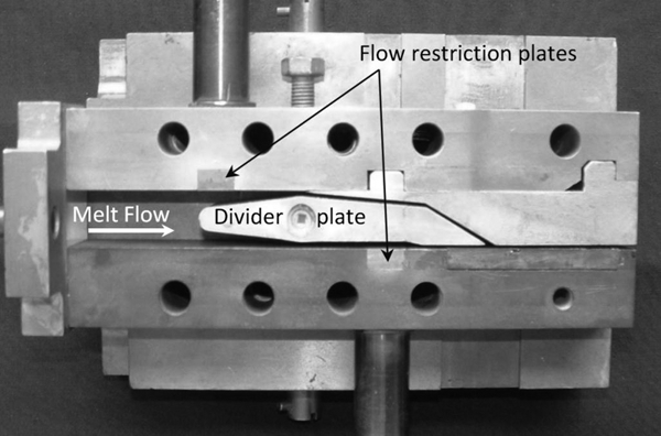
Photograph of single melt coextrusion die having 308 convergent side stream (one side plate removed to show divider plate geometry)
The die had adjustable restriction plates fitted in each of the divided streams. The plates were used to restrict the melt flow in each channel, thus providing a means of altering the stream velocity ratios and consequently stream thickness, at a given melt flowrate from the extruder.
The flow cell was of modular design to take inserts to confer different convergence geometries. The single extruder configuration had a limitation in that it was not possible to alter the stream velocities independently of the relative stream layer thickness. To overcome the limitation, studies were performed using two sets of insert, each conferring a different side stream height. The channel dimensions of these inserts are shown in the schematic of Fig. 2. The parallel channel height was kept constant at 1·0 mm. These die configurations will be referred to as 1·05 and 0·68 mm side stream throughout the rest of this report.
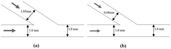
Schematics of channels dimensions of 30° geometry flow visualisation cells
Extruder barrel and die temperatures were set at 200°C throughout the study. Previous experience of these narrow geometries indicated stress fields could only be resolved at low fringe orders. Hence, the extruder screw speed was fixed to produce a constant low mass flowrate of 1·36 (±0·04) g min−1 so that stress field and fringe order could be readily resolved. Mass flow was checked after each adjustment of the channel restriction plates and the extruder speed altered accordingly to maintain the nominal 1·36 g min−1 flowrate. Melt pressure, screw speed and die temperature were monitored and recorded using a National Instruments A–D card and LabView programs developed in-house.
Greater details of the process measurements, techniques and sensors used and imaging system, including the polariscope system used to view stress induced flow birefringence are provided elsewhere.22, 25 Stream thickness, hence position of the interface, was quantified by tracking the procession of natural contaminants/particulates emanating from the point of confluence and along the interface into the die land. Layer ratio is defined as ds/dp, where ds and dp are the respective thickness of the side and parallel melt streams on entry to the die land. This measurement was taken at the immediate entry to the die land since previous work has shown that the layer ratio remains unchanged during the two stream flow in the majority of the die land with the exception of a slight wave oscillation in the stream thickness near the exit of the die. 22 The layer ratio is normalised with respect to the parallel stream layer thickness.
Modelling
Steady state, non-isothermal, two-dimensional finite element simulations were performed by solving the well known mass, momentum and energy conservation equations using Compuplast Virtual Extrusion Laboratory software. The modified Leonov model has been utilised as the constitutive equation. This constitutive equation is based on heuristic thermodynamic arguments resulting from the theory of rubber elasticity,27–29 which mathematically relates the stress and elastic strain as
Results
Stress field and critical layer ratio
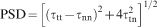
An image showing typical stress birefringence developed during the flow of the melt in the 1·05 mm geometry is shown in Fig. 3. The image is captured when flow in the parallel (bottom) stream was the dominant flow. In this case, the ds/dp layer ratio was 0·36∶1, and wave type interfacial instability occurred. The fringes represent contours of principal stress difference (PSD). It is apparent from observation of the pattern of fringe density and distribution that there are high stress gradients at the corner entry to the die land and the apex of the dividing plate. Previous work provides greater detail on fringe development in this type of geometry and their association with regions of high stress. 22 The image demonstrates the uncertainty in applying optical techniques for accurate analysis of fringe orders. In particular, it is not possible to distinguish the fringe order with any degree of certainty in highly stressed regions as for example occurring at the tip of the divider plate and at the entry corner to the die land.
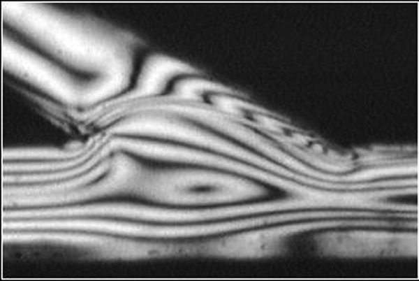
Image of stress birefringence pattern developed in Dow melt at 200°C when processed at mass flow of 1·34 g min−1 in 1·05 mm side channel die (ds/dp layer ratio = 0·36∶1)
Layer and velocity ratios promoting stable and unstable interfaces in the Dow LD150R melt from both geometries are depicted graphically in Fig. 4. Stream velocity ratio is the ratio of theoretical maximum stream velocities as determined by mass continuity and the relative stream heights. Hence, low velocity ratios occur when the parallel stream is the minor flow. Regions marked by arrows to the left and right of the vertical demarcation lines in the graph represent the layer ratios giving rise to wave type instability. The intermediate area defines conditions of stable flow, i.e. represents the stable ‘processing window’ of layer and velocity ratios. Values of critical ds/dp ratios coinciding with the onset of interfacial instability for both die geometries are summarised in Table 1. Two values are given for each die height. These correspond to melt flow when the parallel stream is set as the dominant flow and then when the side stream is made the dominant flow. The coextrusion flow is stable between these ratios for each die.
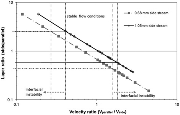
Influence of side channel height on flow stability; left and right arrows define process conditions giving rise to interfacial instability
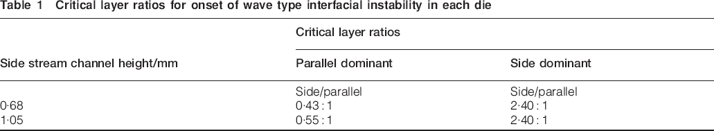
Critical layer ratios for onset of wave type interfacial instability in each die
Modelled flow
A typical adaptive FEM mesh used to describe the coextrusion flow domain in the 1·05 mm side channel geometry is depicted in Fig. 5. A similar mesh is generated for the 0·68 mm geometry. In both cases, the meshes are not static during the iteration process but regenerated every time a new location of the interface is calculated.
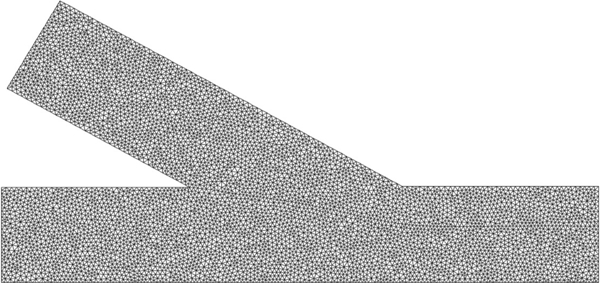
Typical finite element mesh utilised for coextrusion flow modelling of 1·05 mm side stream die
The PSD is given by the following equation
Simulation of PSD contours for Dow melt at 200°C in 1·05 mm side channel geometry with melt flow of1·34 g min−1 and side/parallel stream layer ratio of 0·36∶1
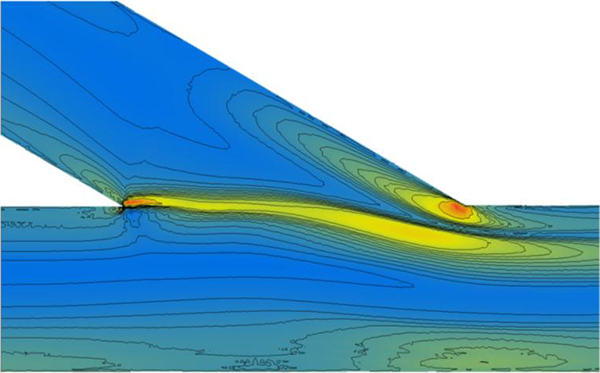
Predicted stress field and interface position at layer ratio 0·1

Predicted stress field and interface position at layer ratio 0·3
Predicted stress field and interface position at layer ratio 0·5
Predicted stress field and interface position at layer ratio 0·6
Discussion
An important observation from the experimental studies, and apparent in data of Fig. 4, is that wave type interfacial instability can occur even when two or more streams of the same melt are coextruded. In this study, wave instability was noted when the two Dow LD 150R melt streams, which are essentially of identical rheology, are coextruded on to themselves. This suggests that even subtle differences in process history, such as imposed by slight differences in geometry of flow paths, is sufficient to produce interfacial instability in melts.
Changing the side stream channel height from 1·05 to 0·68 mm was found to promote more stable flow in the Dow LD150R melt. This is apparent from data in Table 1, i.e. melt flow in the 0·68 mm geometry tolerates a greater difference in stream velocity and layer ratio before the onset of wave instability. Data in Fig. 4 visually portray this. More interestingly, processing is more likely to be stable when the side stream is made the dominant flow stream irrespective of channel height. This is borne out by comparing the critical layer ratios at the onset of wave instability. Taking results from the 1·05 mm geometry as an example, the critical layer ratio at onset of instability when the parallel stream is the dominant flow is only 0·55∶1, as opposed to 2·40∶1 for side stream dominated flow. A similar trend exists for the 0·68 mm side channel die. Coincidentally, there is found to be consistency in critical layer ratio, ∼2·40∶1, for side stream dominated flow for both the 1·05 and 0·68 mm geometries.
It is proposed that the improved process stability of the interface with the 0·68 mm geometry is attributed to greater stretching (extension) of the melt in this minor side stream channel before its confluence with the parallel stream. When flow in the side stream is the minor portion of the total melt flow, the side stream melt is forced to converge on approach to the confluent region. Such convergence is clearly depicted in Fig. 3 by the compression of the fringes in the side stream melt. As melt from the side stream converges with the major parallel stream, it is subjected to extensional flow. Reducing the channel height inevitably leads to increased melt acceleration, and higher rates of extension, during its progress through the convergence zone. The melts are viscoelastic, so increasing extensional strain rates will generate higher normal stresses. It is proposed, and borne out by numerical modelling, that reducing the side stream height increases melt acceleration and stretching, leading to the development of higher normal stresses in the side stream flow on approach to the confluence. As a consequence, normal stresses developed will tend to be similar in magnitude to the normal stress developed in the major stream. That is, a higher level of prestretching in the side stream melt leads to closer balance in the normal stresses of the melt streams across the interface at the confluence region. Since both streams are of the same Dow LD150R grade, and of identical viscoelasticity, it is proposed that subtle differences in extensional history of the melt streams are the key factor influencing flow stability in these geometries. The fact that the critical layer ratio is ∼2·40∶1 for the condition where the side stream is the dominant flow, irrespective of side channel height, supports this proposition. In this case, melt convergence in the parallel stream will be the same for both dies because the channel height is the same at 1·00 mm. The parallel stream velocities at confluence are identical in both cases; hence, melt flow in this channel of both dies is exposed to the same extensional history, and any imbalance in normal stress across the interface for both geometries does not occur until the layer ratio exceeds 2·40∶1.
As shown in Fig. 3, it is often difficult or impossible to extract individual PSD contours from experimentally observed fringes. This is particularly the case for coextrusion flows in very narrow channels or at high flowrates, which often lead to high stress gradients and subsequent high fringe density. Under such circumstances, the individual PSD contours appear to merge to form one broad fringe such that discrimination of individual PSD contours becomes impossible. Hence, accurate numerical simulation procedures would improve the detail in stress field measurements. There is good qualitative agreement between the stress features of experimentally determined PSD contours of Fig. 3 and the numerical data of Fig. 6. The numerical simulation however provides substantially greater detail for the direction normal stress attributes during the coextrusion flow. The simulation clearly shows the broad fringe close to the upper entrant corner to the die land of Fig. 3 to be composed of a multitude of densely spaced fringes.
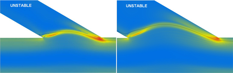
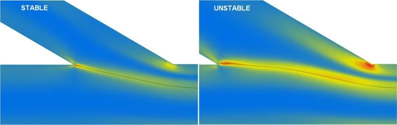
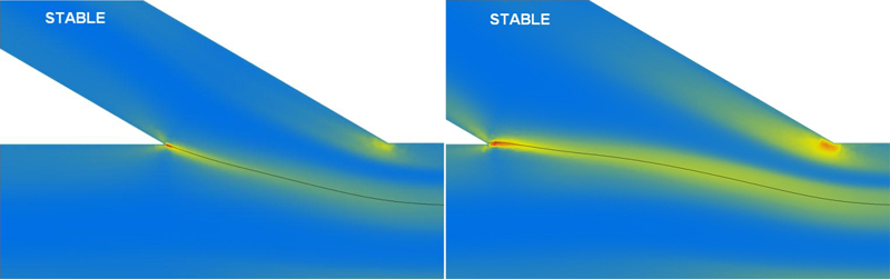
Our proposition that contraction mechanisms improve flow stability, through melt stretching, is supported by numerical simulation of melt flow in these 30° geometries. Stress field simulations are presented in Figs. 7–10. These show both interface position and normal stress τtt contours in the flow direction for a series of layer ratios in the range 0·1–0·6 covering unstable and stable flow regimes for each die. Model predictions for these particular geometries and flowrate indicate a maximum normal stress of ∼300 kPa. This invariably occurred at the apex of the dividing plate and entry corner to the die land in both dies. Using the experimental knowledge of critical layer ratios while comparing the stress field simulations of Figs. 8 with 9, one can see changes in the stress profiles. In particular, interfacial instability occurs when the flow direction normal stress τtt becomes non-symmetric across the interface from the bulk point of view. Furthermore, the transition from stable to unstable flow coincides with a non-monotonic decay in τtt along the interface. As the stress fields are for the normal stress component in the flow direction, it can be concluded that in this specific coextrusion flow arrangement, the main contribution to the unbalanced overall stress PSD across and along the interface comes from the unbalanced stretching. The simulations are in good agreement with the experimental findings with respect to the effect of channel height and its effect on critical layer ratios. Simulations predict interfacial instability to occur when the ds/dp layer ratio is ≤0·4 in the 0·68 mm side stream geometry and at ≤0·5 for the 1·05 mm side stream geometry. This compares favourably with and experimental data showing instability arises at layer ratios of <0·43 and <0·57 in the respective dies.
Accurate numerical modelling clearly provides insight into the mechanism promoting wave type instability. Observing the progression of the stress profiles of Figs. 8–10 clearly shows stable flow coincides with the stress field being symmetric about the interface for both die heights. Instability arises when the converse occurs. Additionally, interfacial instability appears to be driven by state of the stress profile along the interface. This feature is shown when comparing the stress fields for stable and unstable flows in Figs. 7a and 9a. In the former condition, there is a non-monotonic decay in the normal stress along the interface, but the decay changes to a gradual decay when flow stabilises. The simulation findings indicate that interfacial instability is strongly associated with a non-monotonic decay in stress along the interface in addition to an imbalance across the interface. The images depicted in Fig. 7 represent the extreme cases of these stress features and occurs when gross interfacial instability is present during melt is processing at a layer ratio of 0·1∶1 both dies.
Conclusions
Reducing the side stream channel height increases the tolerance of layer ratio before the onset of wave type interfacial instability in the Dow melt at 200°C. The melt is found to tolerate a greater difference in stream height ratio before the onset of interfacial instability when a side stream of narrower channel height is used. It is proposed that the stabilising influence of this geometry is associated with greater melt prestretching leading to increased normal stresses that balance the normal stress field across the interface.
Making the side stream the dominant flow appears to enhance the stability of the coextrusion process irrespective of side channel height. The critical layer ratio for onset of interfacial instability was found to be higher when the side stream was the dominant flow stream.
Modelling revealed that the driving mechanism for interfacial instability was the stress condition both across and along the interface. The instability was predicted when the gradient was asymmetric across, and decayed non-monotonically along, the interface from the point of confluence. It is not possible to present a simple quantitative critical normal stress difference value. It is the non-monotonic nature of the normal stress difference decay along the interface which actually leads to the instability rather than the magnitude of the normal stress difference. That is, there is not a normal stress threshold that cannot be exceeded, but how the stress contour changes as it progresses along the interface. Model predictions for these particular geometries and flowrate indicate that a maximum normal stress of ∼300 kPa occurs at the apex of the dividing plate and entry corner to the die land and is present when flow was stable. However, when two 300 kPa stress points occurred along the interface, then flow would become unstable. This value of 300 kPa would undoubtedly change if the total mass flowrate in the system changed.
Footnotes
Acknowledgements
The authors wish to acknowledge the IRC in Polymer Engineering, University of Bradford, Grant Agency of the Czech Republic (grant no. 103/09/2066) and Operational Programme Research and Development for Innovations cofunded by the European Regional Development Fund and national budget of Czech Republic, within the framework of project Centre of Polymer Systems (reg. no. CZ.1·05/2·1·00/03·0111) for the financial support.