
Abstract
In the present work, reference and nano-modified unidirectional and quasi-isotropic, epoxy matrix, carbon fibre reinforced polymers, were exposed to distilled water at hydrothermal environment. Water uptake was investigated as a function of the CNT matrix wt-% content up to saturation level. In parallel the variation of glass transition temperature Tg was also monitored using DMA tests. The distilled water absorption process was modelled following the Fick's law, and the experimental results found to be in very good agreement to the theoretical predictions up to saturation. During the tests, at defined time intervals, the variation of the electrical conductivity of the investigated materials was studied and a correlation between the water absorption and the variation of the electrical conductivity was established. Finally, all the reference materials and the ones concluded at the saturation stage were exposed to broadband dielectric measurements at frequency range of 0·1 Hz to 1 MHz.
Keywords
Introduction
Carbon fibre reinforced composites (CFRPs) are nowadays used extensively for high performance applications among others in transport industry (aerospace, rail, automotive and marine) in order to gain to the direction of greening, due to high stiffness and strength to weight ratios of these materials. In the course of operating life, composite materials are often subjected to severe environmental conditions. Degradation behaviour of polymeric composites working in harsh environment such as temperature and humidity is one of the important issues. It is well known that polymer–matrix composites are susceptible to heat and moisture. Diffusion of water into epoxy resins or epoxy–matrix composites has been extensively studied and relevant results can be found in literature.1–5 Also was found that the higher the temperature, the higher the moisture uptake rate of the composites and the more intense the nucleation of damage. 6 In addition, the interfacial adhesion degradation in-between the constituents of the polymeric composites depend upon the conditioning temperature and exposure time, resulting to an overall degradation of their mechanical performance. 7
Certain thermomechanical properties of high performance composites are strongly affected by moisture absorption. 8 Moisture absorption at certain stages causes plasticisation of the polymer matrix with a concurrent swelling and lowering of its glass transition temperature Tg.9–11 It has been proposed 12 that the transport of moisture bellow Tg is a three-stage process:
diffusion of water through the bulk of the polymer network
absorption of moisture on the surface of vacuoles that define the excess free volume of the glassy structure
through hydrogen bond formation between hydrophilic groups associated with hydroxyl or amine groups attached to the polymer chain and the water molecules.
The available free volume in the resin influences the water equilibrium concentration and can also occupy microvoids and other morphological defects.14–18 Various models have been proposed to describe the kinetics of water diffusion. More favoured treatments include those based on Fick's law. 19
The glass transition temperature Tg is very important parameter of epoxy resin and epoxy matrix composites because the Tg establishes the service environment for the materials use. Usually, when the material is exposed in a hydrothermal environment the Tg decreases and, therefore the service temperature of the material changes. Moreover, incorporation of fillers into polymeric matrices leads to changes in their glass transition temperature Tg, 21 probably because of the immobilisation of the polymer segments close to the surface of the filler particles.
A new field of interest in the mechanics of composite materials has opened by the introduction of a nanoscaled reinforcement into conventional fibre reinforced composites, since a multiscale reinforcement is concluded, thus affecting the mechanical/fracture performance of the composites and resulting to multifunctional material behaviour (in terms of electrical and thermal behaviour). An attractive, extensively studied, class of nanofillers for the matrix modification of fibre matrix composites are carbon nanotubes (CNTs). CNTs them self, possess unique properties, such as a high elastic modulus at the scale tera Pa, huge aspect ratio, and an extremely large specific surface area (or the interfacial area when incorporated in the matrix).22, 23 Another attractive property of some classes of CNTs is their high electrical conductivity that makes polymer matrices conductive at very low wt% content (over the percolation threshold). Thus, the concluded fibre composites are turn to conductive materials as in the case of non-conducting reinforcements, or improve their electrical conductivity, mainly in the normal to the fibre directions, in the case of carbon reinforcement. In general, the conductivity of these composites depends upon the CNT concentration and on the contact resistance between adjacent particles, when a sufficient amount of CNTs is loaded in order to exceed the percolation threshold. In the case of CNTs the percolation threshold has been reported to be very low, at the level of 0·1 wt-% content, or even lower,24–26 depending on the homogeneous distribution of the CNTs into the polymer matrix, and the absence of agglomerated fillers. Finally the electrical conductivity and electrical resistance of such systems has been reported to directly correlate with the macroscopic strain applied to the material and with the internal damage that accumulates in the material during its service life.27–29
The present work, investigates the behaviour of epoxy matrix CFRPs in hydrothermal environment. The work deals with the study of the hydrothermal behaviour of reference CFRPs, both Unidirectional (UD) and quasi-isotropic, as well CNT modified matrix UD CFRPs at different wt-%CNT content. More precisely, MWCNTs (multi wall carbon nanotubes) are incorporated in commercial epoxy (LY564/Aradur 2954) systems, which are subsequently, used for manufacturing unidirectional and multidirectional (quasi isotropic) CFRP laminates. Unmodified and CNT modified CFRPs are subjected to hydrothermal loadings for comparison purposes. During the environmental conditioning, the specimens were weighted at specified time intervals, and the water absorption vs. time was recorded and then analysed and compared against theoretical predictions of Fick's law. Additionally DMA experiments have been performed. Finally electrical measurements were carried out as different stages of the water absorption process, using the four-electrodes method. A correlation of the effect of hydrothermal loading on the electrical conductivity of the materials was also established.
At the end of the work, all the reference materials and the ones concluded at the saturation stage, were exposed to broadband dielectric measurements at frequency range of 0·1 Hz to 1 MHz.
Experimental
Materials and specimen preparation
The epoxy system used for the fabrication of CNT doped resins and CFRPs was the Araldite LY564/Aradur HY2954 which was supplied from Hunstman advanced materials, Switzerland. The multiwall CNTs (MWCNTs), which were homogeneously dispersed in the matrix system, were supplied by ARKEMA, France. According to the provider, the CNTs have a diameter of 10–15 nm and their length is more than 500 nm, resulting to aspect ratios (length/diameter) varying between 30 and 50.
Specimens of 16 plies, [0]16, of UD carbon fibre (CF) laminates and MD [(0/+45/−45/90)2]s quasi-isotropic laminates were manufactured for this investigation. UD carbon fibres reinforcement was supplied by Hexcel, Germany, having specific weight of 160 g m−2.
The epoxy matrix modification has been performed by the dispersion of the multiwall CNTs (MWCNTs) into the matrix materials. For the epoxy system the dispersion was carried out using a torus mill device (VMA Getzmann GmbH). That mill creates high shear forces by a high speed rotating disc, and the nanoparticle agglomerates are crushed owing to the milling effect generated by zirconium dioxide beads. The beads have a diameter of 1·2–1·7 mm and cause strong shear action and collision effects. The dissolver disc provides additional shear forces and maintains the vortex flow. The mixing speed was 2000 rev min−1 for 3 h. Modified matrices with a CNT content varying from 0·1 to 1 wt-% were prepared. All compounds were stirred in a vacuum container to avoid the inclusion of air. Modified and unmodified matrices were used to manufacture the laminated plates. The aforementioned process is schematically shown in Fig. 1.
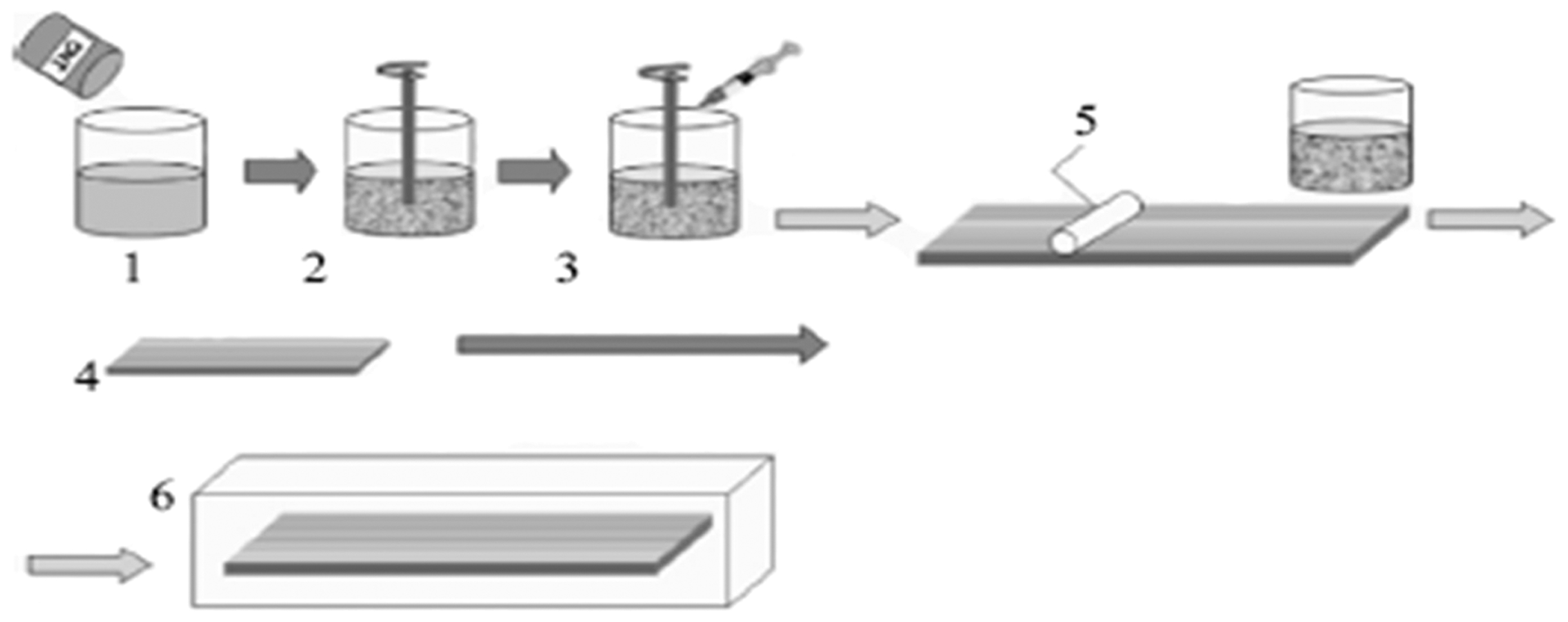
Outline of specimen preparation: 1, addition of MWCNTs to systems; 2, mixing in torus mill device at 50°C in vacuum; 3, addition of curing agent and mixing; 4, making CF reinforced laminas; 5, preparation of modified and unmodified CFRP laminates by hand lay-up; 6, curing in autoclave (1 h at 80°C+8 h at 140°C) 25
The dimensions of the epoxy specimens used for the present study were 59×12×2·5 mm3 (Fig. 2). Five different samples of each type of material were utilised for measuring the water absorption and the rest of the properties reported in this work.
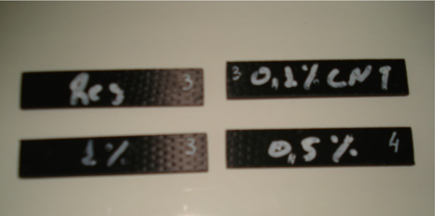
Overview of LY 564 epoxy specimens
Methodologies and devices
A distilled water bath with temperature control capabilities was used for the hydrothermal conditioning test of the specimens at 80°C. All specimens before placed into the bath were dried in an oven at 50°C for 24 h. The weight was measured using an electronic balance with an accuracy of ±1 mg. The composite samples left to stay into the distilled water bath for over 1440 h (60 days) exposure time. The specimens used for water absorption measurements were removed at specified time intervals, wiped, and then weighted. The weight gain was calculated using the formula
After hydrothermal environment exposure, the saturated specimens were placed in an oven at 60°C in order to analyse their desorption profile.
Measurements of the variation of the glass transition temperature Tg were performed for all the epoxy samples with neat and doped matrix at four different absorption stages, using dynamic mechanical analysis (DMA 938 DuPont). The three point bending set up was applied at a frequency of 1 Hz and oscillation amplitude of 0·1 mm. The temperature range was 25–200°C and the rate of temperature increase was 2°C min−1. DMA tests were performed at four different exposure stages for the epoxy matrix composites. The first stage was at the reference conditions, before any hydrothermal exposure applied, the second was after 1/3 of the total exposure time, the third stage was the end of the exposure period, while the last stage was after drying the samples, completing the desorption phase. The samples passing DMA test was eliminated from the rest of the study. During the water absorption experiments, the lateral surfaces of the samples were isolated using appropriate varnish.
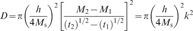
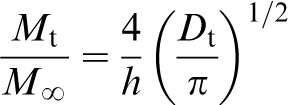
Fick's diffusion law is employed in order to describe the diffusion coefficients for both the UD as well as the quasi isotropic composite CFRP laminates, in the through the thickness direction. The 1D diffusion coefficient concluded by Fick's law is
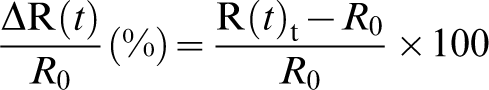
The specimens used for electrical resistance measurements also placed in the same distilled water bath, for the same period and at the same temperature. In order to facilitate the electrical resistance measurements during the hydrothermal exposure, specimen's ends were prepared accordingly. After local surface preparation, the ends of the specimens were coated with a conductive silver paint. Then, appropriate electrodes were attached on specimen ends with conductive epoxy glue. Finally specimen's ends were coated carefully with silicone (Figs. 3 and 4). This procedure effectively eliminates the fluctuations in resistance measurements caused by differences in connector clamping pressures, or by deterioration of electrode properties due to the hydrothermal exposure process. The resistance measurements were performed simultaneously with the weight gain measurements by using a digital Keithley multimeter of accurancy 0·1 mΩ. In that sence resistance measurements were provided across the specimens length. The relative resistance was calculated by equation (4)
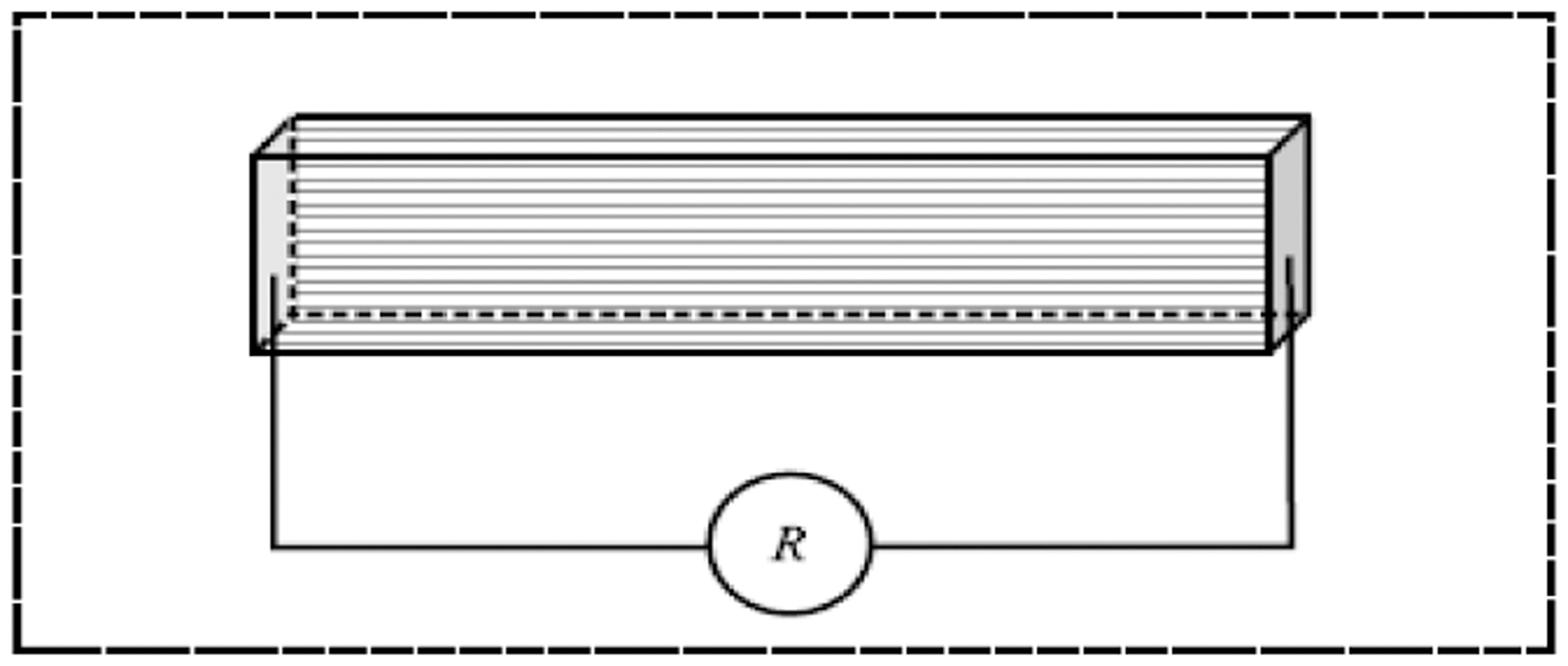
Configuration of electrical resistance measurements
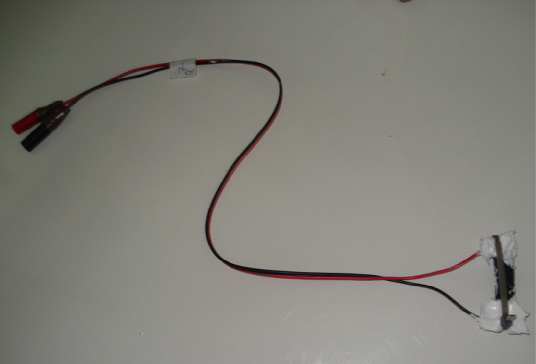
Overview of electrical configuration, used to measure electrical resistance
Finally, experiments for the dynamic electrical characterisation of the studied materials were conducted by means of broadband dielectric spectroscopy (BDS) in the frequency range of 0·1 Hz to 1 MHz, using Alpha-N frequency response analyser and a 1200 BDS dielectric cell provided by Novocontrol. Each composite type was subjected to dielectric spectroscopy being at three different states: first dry, at its reference state, second when it was reached the saturation level and finally, after drying the material when saturation had been achieved. In this case the dielectric measurements were performed in the through the thickness direction.
The dielectric relative permittivity (ϵ′) and dielectric loss (ϵ″) were calculated from the real and imaginary values of impedance as follows
In the above equations, Z′ is the real part of the impedance, Z″ is imaginary part of the impedance, C0 is the cell capacitance, A and d are the area and thickness respectively of the tested specimens.33,34
Results and discussion
Figure 5 presents the weight gain of the reference (unmodified), CNT modified and quasi isotropic (unmodified) epoxy CFRP laminates (LY 564 system). Within the limits of experimental error, all the CFRP epoxy systems reached the 98% of their saturation value after 100 h of exposure. The quasi isotropic reference system exhibited the lower water weight gain at saturation compared with the all the UD and UD-CNT modified systems, reaching a weight gain approximately at the level of 0·39%. The water uptake of the reference UD composite is at the level of 0·59%, having an increase of 34% compared against the reference quasi isotropic CFRPs. The presence of CNTs into the epoxy matrix leads to an increased water uptake, reaching the level of 0·7% for CNT content of 1 wt-%. On the other hand, the water gain is higher; the higher is the wt-%CNT content. This supports the concept that the modification of epoxy matrix with CNTs concludes to an increased interfacial region, which served as a route for higher water uptake. However, the rate of water gain remains almost constant in all the cases, but the quasi-isotropic CFRPs.
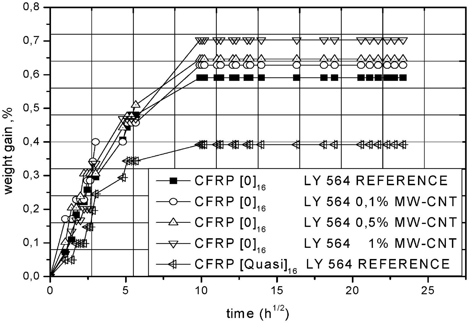
Weight gain % versus square root of time for UD unmodified, modified and MD (Quasi) unmodified CFRPs (LY 564) epoxy systems
Figure 6 presents the change of glass transition temperature Tg for epoxy matrix CFRPs, at four different stages of water absorption, as a function of CNTs concentration and the exposure time. In this figure a significant degradation of Tg is observed when the water absorption process is established (1/3 of the total exposure time) as well as at the saturation stage. This is an expected behaviour, since when water molecules come between the chains of matrix material; they break down the initial Van der Waals bonds resulting to the releasing of chains. The quantity of energy that the system needs reduces when the amount of released chains increases. This is the basic mechanism that Tg decreases. Finally, when the samples are dried, at the end of desorption stage the Tg is recovered, at slightly higher value compared to the reference one. This phenomenon of Tg increase is associated to the hydrolysis effect within the matrix.
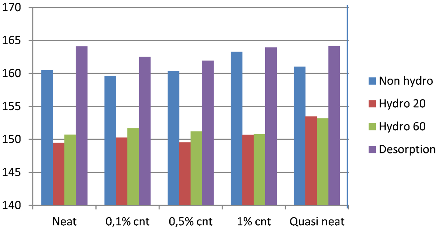
Glass transition temperature (°C) for LY 564 systems
More precisely, as it is expected the introduction of the CNTs into the matrix material makes the epoxy network structure more rigid and this is reflected to the slightly increase of Tg of the epoxy systems from 160°C for the neat (0% CNTs) samples to a value of 163°C in the case of 1 wt-%CNT contents. In the case of intermediate wt-% CNT content the Tg value of the system remains almost constant. The value of Tg at the saturation state reduces to 151°C, almost constant for all the cases of CNTs content as well as for the neat resin system. This is not the case for the quasi-isotropic reference samples, where the reduction is lower (Tg around 153°C) due to the lower water absorption. The reduction of Tg in the case of UD and UD-CNT modified CFRPs represents a degradation average of 7%. Finally at the stage of desorption a recovery of Tg is observed appearing also a slight increase ranging between 2 and 3°C.
Figure 7 shows the experimental and the calculated theoretical results for the water absorption for the different CFRP laminates and the different CNTs modification level of the matrix material. Fick's law provides good correlation to the experimental results until saturation point.
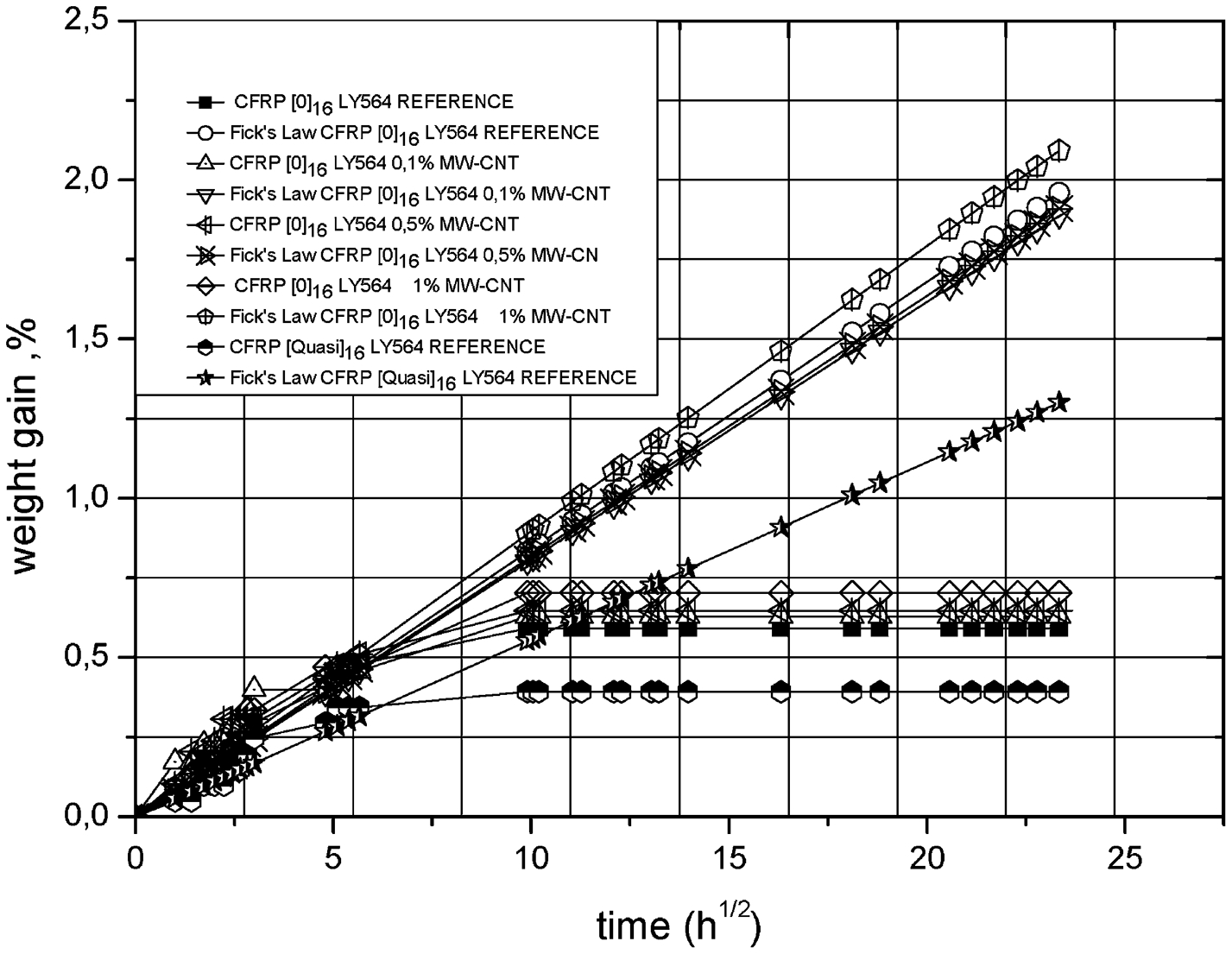
Results of Fick's law analytical modelling against experimental data for LY 564 matrix systems
The diffusion coefficients D for the different CFRPs and for the different wt-%CNT contents are given in Table 1.
Diffusivity D for different concentrations of CNTs for LY 564 matrix systems

In general, the diffusion coefficient of the epoxy based materials increases when the presence of CNTs increases in the matrix. The incorporation of 1 wt-% of CNTs leads to an increase in diffusion coefficient at the level of 30%. On the other hand, the diffusion coefficient for the quasi-isotropic laminates is almost the same as in the case of UD CFRPs, although the final water gain of quasi isotropic laminates is significantly lower the that of UD ones.
Figure 8 presents the normalised variation of the electrical resistance dR/R (%), of the reference (unmodified), CNT modified and quasi reference (unmodified) epoxy CFRP laminates, as a function of the square root of exposure time. First of all, one has to notice, that the measurements were carried out along the longitudinal direction of the samples. The resistance of the reference UD CFRP (0% wt of CNTs) specimens fell rapidly with exposure time, reaching at the saturation level a difference (decrease) of 25%. The presence of the CNTs increase the difference of the electrical resistance as a function of water uptake, concluded at the saturation point to a decrease of almost 40% in the case where a CNT loading of 1 wt-% has been used. Finally in the case of quasi isotropic unmodified CFRPs the same pattern is followed, decreasing resistance as a function of the square root of exposure time, concluded at the saturation point to a decrease of almost 42%. Another interesting result drown based on Fig. 8 is that the rate of change (decrease) of the electrical resistance is higher at higher CNT loading.
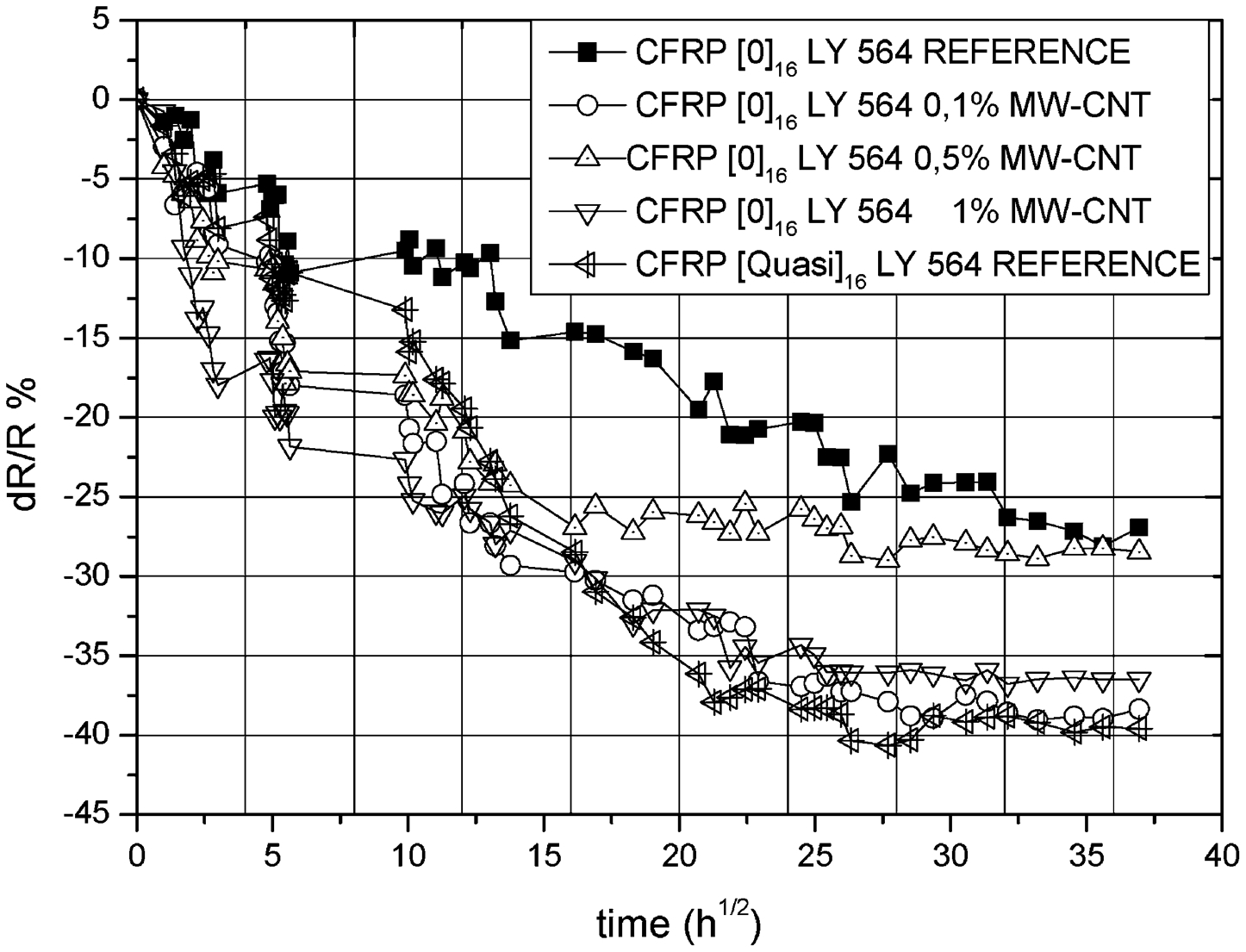
Normalised variation of electrical resistance dR/R (%), versus square root of time for neat, modified and quasi-neat CFRPs (LY 564) epoxy systems
Figure 9 presents the normalised variation of the electrical resistance dR/R (%), versus weight gain of CFRP samples in the case of UD CFRPs both reference and modified ones, as well as for the reference quasi isotropic laminates. As a general trend, for all the cases, it is obvious that the water uptake results to an actual resistance decrease (increase in electrical conductivity). The correlation between the water uptake and the change of the normalised resistance is obvious. This relation is clearly non linear and is strongly depended upon the presence of the CNTs in to the matrix material. On the other hand, the presence of CNTs into the matrix material of CFRPs amplifies the dependence of electrical resistance (conductivity) on the water uptake.
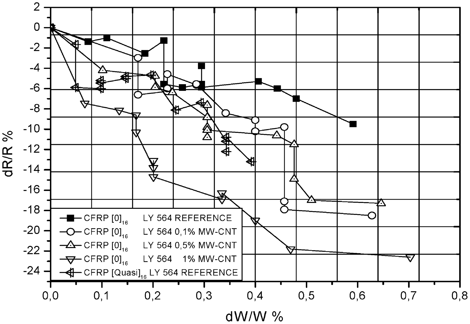
Normalised variation of electrical resistance dR/R (%), versus weight gain dW/W (%) for the neat, modified and quasi-neat CFRPs (LY 564) epoxy systems
Figures 10–12 illustrate the electrical conductivity (inverse resistivity) versus frequency, for LY564 of the UD-CFRP, both reference and CNT modified, at three different stages, as a function of the concentration of the CNTs. In this case all the measurements have been performed in the through the thickness direction. The three different stages indicated above correspond to the reference material state prior of any hydrothermal exposure, the material at the saturation point and finally the material after desorption (succeeded by overnight heating at 60°C).
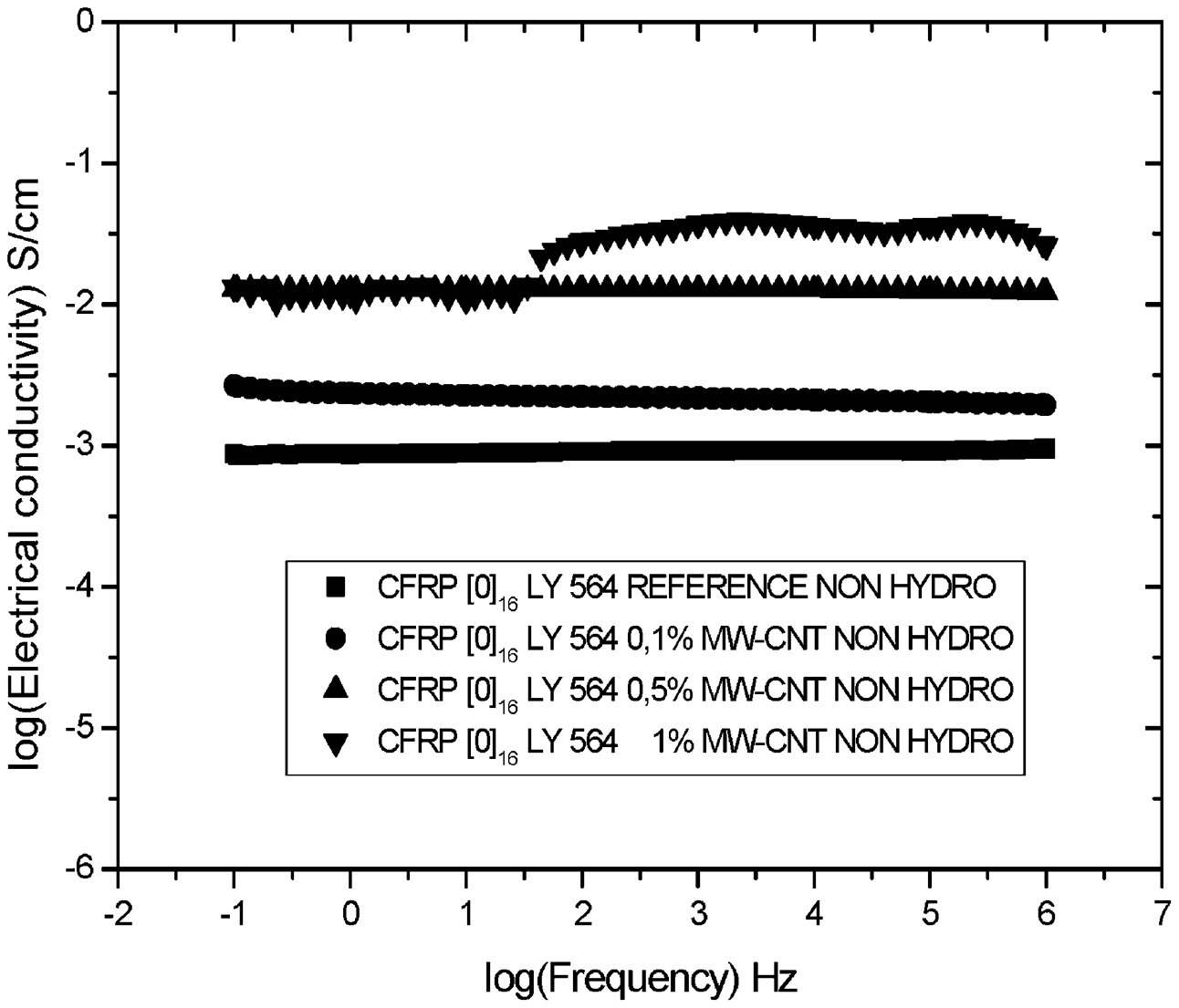
Electrical conductivity versus frequency, at initial (non hydro) point for LY 564 epoxy systems
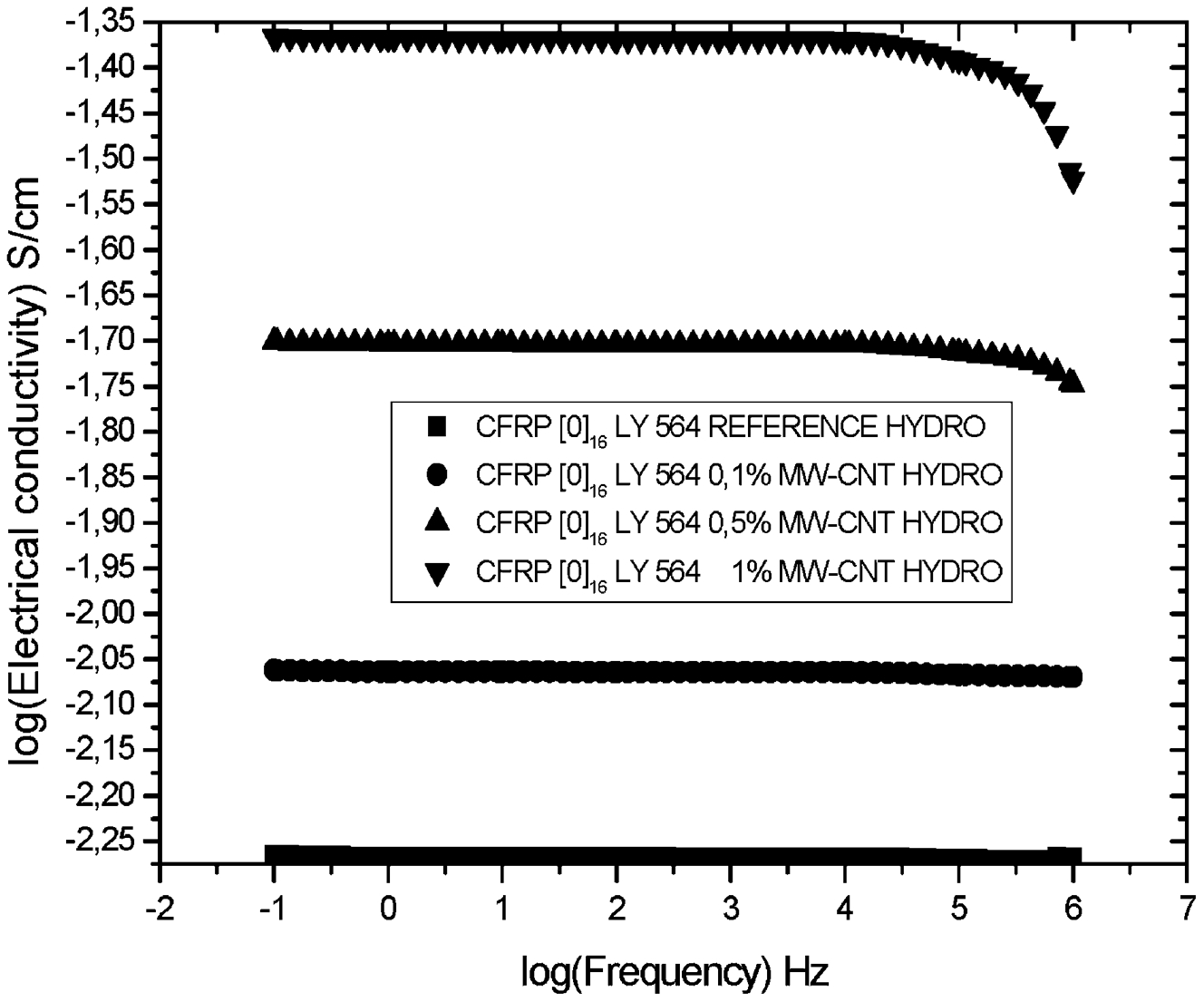
Electrical conductivity versus frequency, at saturation point for LY 564 epoxy systems
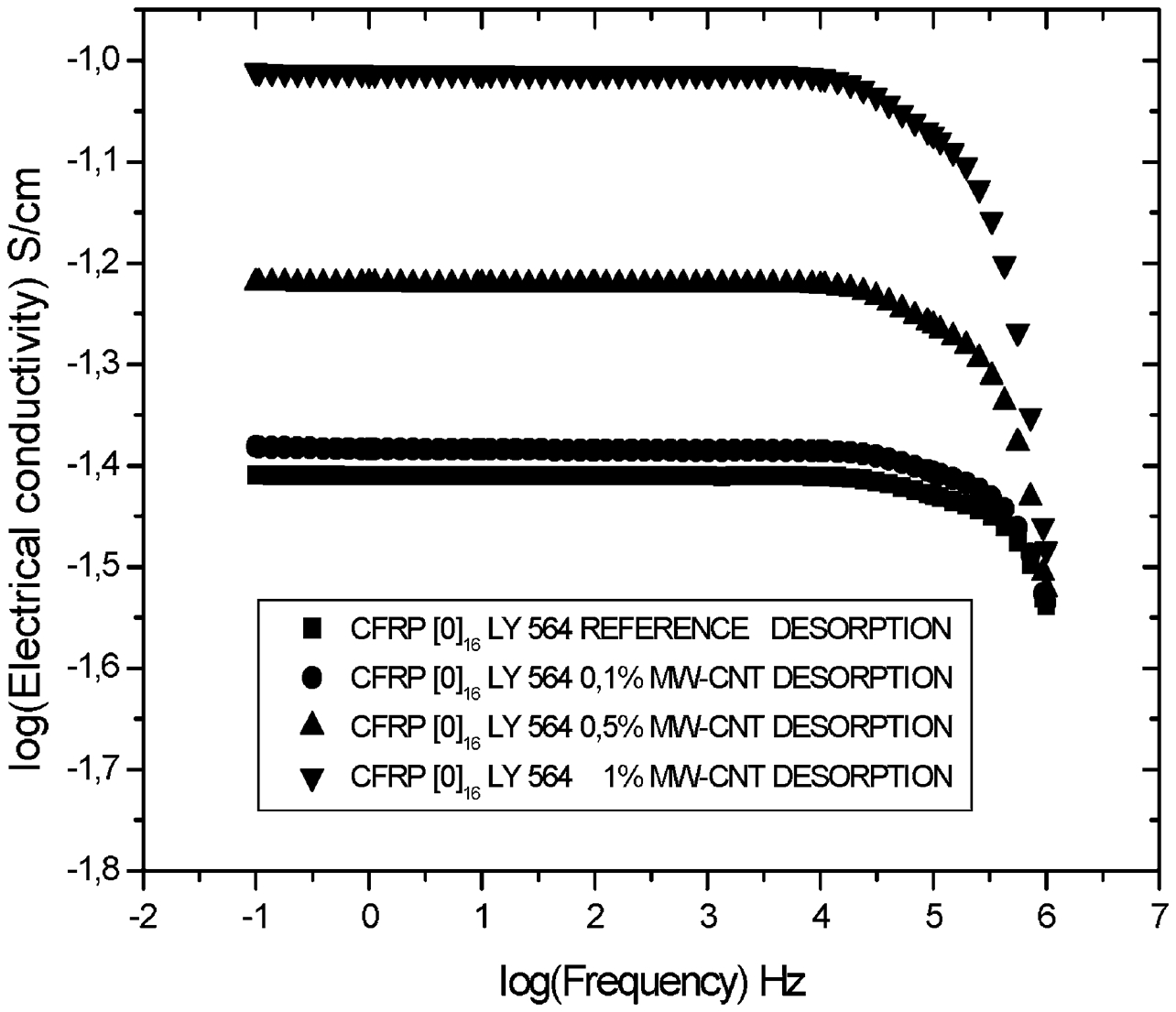
Electrical conductivity versus frequency, at desorption point for LY 564 epoxy systems
In general, the electrical conductivity versus frequency remains almost constant for the entire frequency span (up to 1 MHz) independently of their CNTs modification, and for all the exposure stages, but at the desorption stage, where it holds true up to 10 kHz, and after this frequency value a decrease in conductivity is monitored. More precisely, when the wt-%CNT content increases, as it is expected, conductivity increases. On the other hand, as it was noticed earlier, at desorption stage, all the epoxy matrix CFRP samples, both modified and non-modified converge at the same conductivity value at the frequency of 1 MHz. The conductivity decrease in this case is higher, the higher the CNT content is.
Finally in Figs. 13–16 rearrangement of the formerly presented results is given. In these figures, the electrical conductivity versus frequency, for the CFRP laminates are illustrated at three different stages of each material system, both for the non-modified as well as for the CNTs modified matrices. For that systems at saturation the conductivity increases, while this behaviour is the same at the stage of desorption (conductivity increases more). This means that the absorption of distilled water inside the material structure during the hydrothermal exposure forms this type of modifications that brings closer the carbon fibre conducting phase, reducing in parallel the contact resistance between the fibres. In the absence of uptake water (dried samples), the conductivity increases further as a result of the reduced contact resistance between the fibres and the dry state of the material. This pattern holds true in all the cases of CFRP epoxy matrix system, independently of the CNTs content.
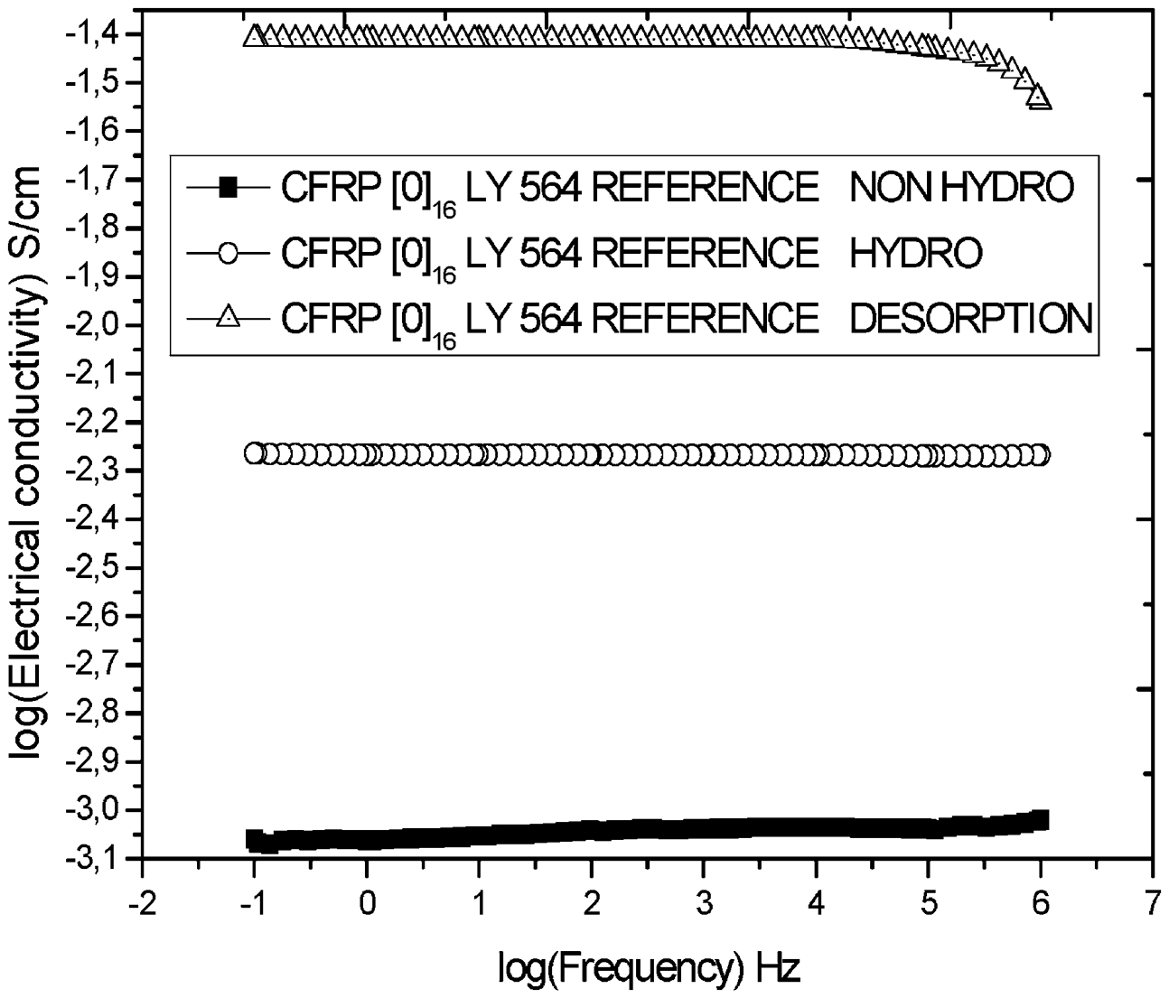
Electrical conductivity versus frequency, at 3 stages for LY 564 epoxy reference system
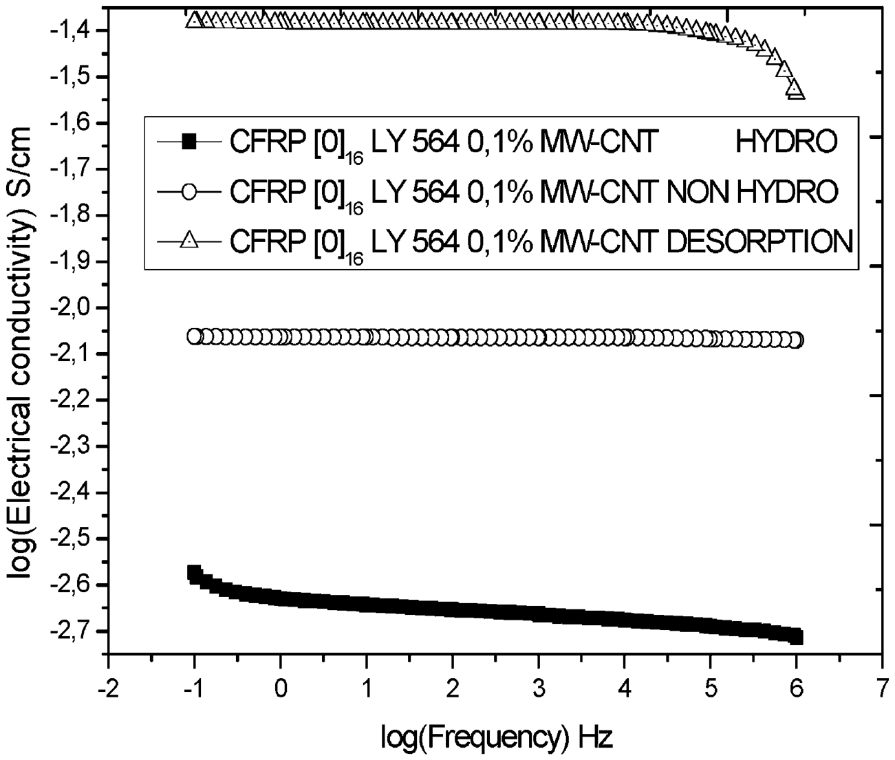
Electrical conductivity versus frequency, at 3 stages for 0·1% MW-CNTs LY 564 epoxy system
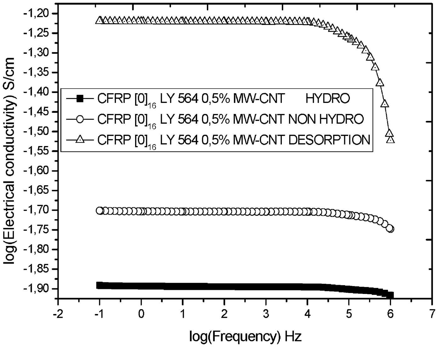
Electrical conductivity versus frequency, at 3 stages for 0·5% MW-CNTs LY 564 epoxy system
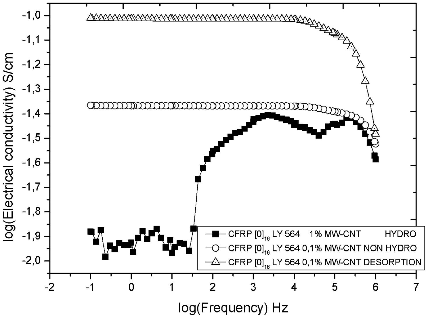
Electrical conductivity versus frequency, at 3 stages for 1% MW-CNTs LY 564 epoxy system
Conclusions
The current study, investigated the effect of hydrothermal exposure on CFRP materials with unmodified and CNT modified matrix. The weight gain was measured as a function of the exposure time at water absorption experiments. Glass transition temperature values at the saturation conditions were measured and compared against the reference Tg of the materials. Theoretical modelling of the water uptake process was performed using linear Fick's law. Theoretical results concluded are very close to experimental ones until the saturation point.
Finally, the variation of the electrical properties of the materials at the different levels of weight gain was also investigated.
The weight gain of reference specimens was very close to that of the specimens with modified matrix. The quasi isotropic unmodified samples presented lower weight gain compared against the UD reference CFRPs.
At electrical experiments, we observe that electrical resistance decreases rapidly with the exposure time monotonically, especially for epoxy systems.
In conclusion, the hydrothermal exposure of CFRPs in distilled water generally reduces the resistance and makes materials more conductive, and this effect provides an opportunity of evaluation of the water uptake by using appropriate electrical resistance measurements.