
Abstract
Low density polyethylene (LDPE)/ultrahigh molecular weight polyethylene (UHMWPE) and LDPE/poly(ethylene-co-vinylacetate) (EVA) blends were tested and compared with respect to their environmental stress cracking resistance (ESCR) using the Bell telephone test. The time to failure in the ESCR test improved with increasing UHMWPE and EVA content, and considerable improvements were produced when an UHMWPE weight fraction of 0.4 and EVA weight fraction of 0.03 were used. Thermal and morphological studies were conducted, and a relationship between morphological features and composition was established. Furthermore, the failed specimens were further characterised by scanning electron microscopy and fractographic methodology to investigate the failure mechanism for ESCR samples.
Introduction
Polyethylene (PE), as one of the most widely used general plastics with good ?ow properties, has drawn much attention of both industrial engineers and academic researchers. It is widely used in outdoor applications in which dielectric, mechanical and thermal behaviours combined with high environmental stress cracking resistance (ESCR) are a matter of major concern. 1 Another kind of PE, ultrahigh molecular weight PE (UHMWPE), offers good abrasion resistance, non-toxicity, high impact resistance (even at cryogenic temperatures), high toughness, excellent fatigue resistance and especially outstanding ESCR.2–4 Ethylene copolymers such as poly(ethylene-co-vinylacetate) (EVA) are produced by free radical polymerisation in a bulk process, such as that used for low density PE (LDPE) production.5, 6 PE/EVA blends are widely used in many applications such as shrinkable films, multilayer packaging, and wire and cable coating.6–9 Addition of EVA onto different grades of PE improves their toughness, transparency, ESCR and the capacity of the filler carrying. As a result, blends of UHMWPE or EVA with LDPE would be expected to yield an improvement in ESCR.
Semicrystalline polymers such as PE often show brittle fracture under stress if exposed to stress cracking agents. In such polymers, the crystallites are connected by the tie molecules through the amorphous phase. The tie molecules play a decisive role in the mechanical properties of the polymer through the transmission of load. Stress cracking agents act to lower the cohesive forces, which maintain the tie molecules in the crystallites, thus facilitating their ‘pullout’ and disentanglement from the lamellae. Consequently, cracking is initiated at stress values lower than the critical stress level of the material. In general, the failure process begins with the embrittlement of the polymer. Then, the crack initiation takes place, which is favoured by the acting load. ESC type of failure is characterised by the presence of macroscopic cracks and a fibrillar structure of the craze, formed ahead of the crack. 10
The modifying effect of the EVA on the ESCR of LDPE has been reported by Borsova and Kressler, 9 and they found that EVA species considerably improved the ESCR of LDPE because the EVA particles can stop crack propagation. However, up to now, no information has been reported on the ESCR behaviour of LDPE/UHMWPE systems. Blending with dispersed elastomeric particles is a well known method to improve the fracture toughness of polymers and has over the past decades led to a number of materials that are now widespread in practical applications.11, 12 Morphological examinations clearly revealed a phase separated morphology for the LDPE/UHMWPE and LDPE/EVA systems.13, 14 Since phase structure plays an important role in the blends' behaviour,1, 15 study of the fracture toughness and its relationship with the morphological properties of these blends can attract great interest from industrial to academic points of view.
The main objective of the present work was to study the fracture behaviour (ESCR) of LDPE/UHMWPE and LDPE/EVA blends. Attempts were made to investigate the relationship between the fracture behaviour and the phase morphology of these blends.
Experimental
Materials
The materials used in this study were LDPE and EVA with a melt index of 1.8 g/10 min and 2.5 g/10 min respectively. The LDPE, with the trademark 2210H, was supplied as pellets by Lanzhou Petrochemical Corp. (Lanzhou, Gansu, China). UHMWPE was supplied as a powder by Beijing Eastern Petrochemical Co. Ltd (Beijing, China), with a molecular weight of ∼2500 kg mol(1. EVA copolymer grade 460, containing 18% VA and with a density of 941 kg m(3, was obtained from DuPont (USA). Antioxidant named XH-245 (Kelong, Chengdu) was used to prevent thermal oxidative degradation.
Sample preparation
In this study, LDPE/UHMWPE and LDPE/EVA blends were prepared by melt blending. The melt blends of LDPE/UHMWPE and LDPE/EVA were blended in a mixer (Rheomix 600, Haake, Germany) at 190°C. The LDPE/UHMWPE blends with the compositions of 100/0, 90/10, 80/20, 70/30 and 60/40 (w/w) were named LU0, LU10, LU20, LU30 and LU40 respectively. The LDPE/EVA blends with the compositions of 100/0, 97/3, 95/5, 93/7 and 90/10 (w/w) were named LE0, LE3, LE5, LE7 and LE10, separately. Then, the melt blends were compression moulded into desired discs at 170°C for measurements. In the preparation of all the blends, the polymers were stabilised by addition of 0.5 wt-% antioxidant to prevent thermal oxidative degradation.
Differential scanning calorimetry
The melting and crystallisation behaviour of each blend were determined using DSC 204 equipment (Netzsch Co., Germany). Experiments were carried out with 6–8 mg of sample under dry nitrogen. All samples were first heated to 165°C at a rate of 10°C min− 1 and held at 165°C for 5 min, and then cooled at a rate of 10°C min− 1 to 20°C and held at 20°C for 5 min. They were then scanned from 20 to 165°C at a rate of 10°C min− 1. Crystallisation and melting temperatures were obtained from the cooling and the second heating thermograms respectively.
Mechanical properties
Tensile testing was determined according to ASTM D638 using an Instron 5562 materials tester. The samples were tested at room temperature with displacement rates of 100 mm min− 1.
ESCR test
This test was performed according to ASTM D1693. Ten notched specimens (38 × 13 × 3mm) were curved into ‘U’ shape and attached to a frame. These samples were then suspended in aqueous 10% Igepal CA-630 solution at 50°C. The time to failure is defined as the time when 50% of the samples failed during the ESCR test suggested by ASTM D1693.
Scanning electron microscopy
The samples were cryogenically fractured in liquid nitrogen, and then, all the surfaces were gold coated to enhance image resolution and to avoid electrostatic charging.
After the ESCR test was completed, the failed samples were collected for further analysis of the crack surface by scanning electron microscopy (SEM). Two different sample morphologies were characterised: (i) fracture surface observation by the failed samples to obtain the morphology of the crack surfaces and (ii) cross-section view of ESC by microtome sectioning parallel to the crack direction. The morphology of the surfaces was observed by a SEM (JSM-5900LV JOEL, Tokyo, Japan) instrument using an acceleration voltage of 5 kV.
Results and discussion
Thermal analysis
The melting and crystallisation curves of LDPE/UHMWPE blends are plotted in Fig. 1a and b respectively. Blends of LDPE/UHMWPE show three endothermic peaks as shown in Fig. 1a. In melting studies of mixtures of linear and branched PEs, some investigators16, 17 reported that differential scanning calorimetry (DSC) experiments revealed three endothermic peaks. An intermediate peak between the UHMWPE and the LDPE peaks has been associated with the fusion of a co-crystal, formed from linear and branched PEs.
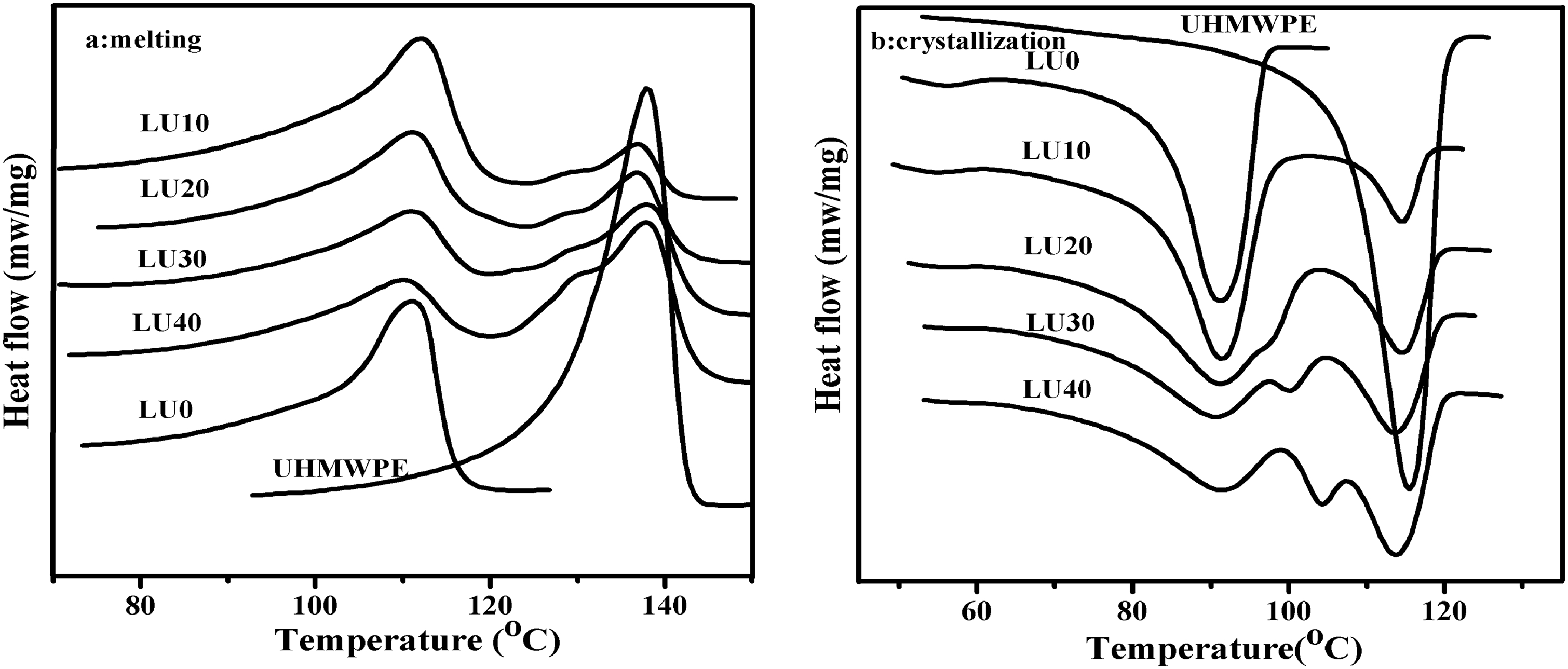
Melting and crystallisation curves of LDPE/UHMWPE blends: a melting; b crystallization
Figure 1b also shows that the crystallisation temperatures of both LDPE and UHMWPE are depressed by the other component instead of closing to each other. In the polymer blend melt, when the temperature decreases, thermal perturbations are due to different rates of crystallisation between LDPE and UHMWPE, and the PE component, which is in the structure of emulsion in the melt, enters into the near growing crystal nucleus, leading to liquid–solid phase separation.13, 18
DSC heating and cooling curves obtained for LDPE, EVA and their blends are presented in Fig. 2a and b. It has been reported that the presence of two peaks for all the LDPE/EVA blends, except 90/10 (w/w) LDPE/EVA blend, corresponding to the melting point of different crystalline types, verifies the immiscibility of the LDPE and EVA crystalline phases. In our study composition range ( < 10 wt-% EVA), a single melting and crystallisation peak observed for all the blends verify the high extent of co-crystallisation in this blend composition. For all the blends, the depression of melting temperature for LDPE crystalline phase to lower temperatures is due to the dilution effect of EVA and/or co-crystallisation of LDPE with part of EVA. On the other hand, the nucleation effect of PE crystallites and some part of PE chains in the amorphous phase can be responsible for increasing the crystallisation temperature of EVA. 19 These results showed that LDPE/EVA blends are not completely immiscible and there is a partial miscibility between LDPE and EVA in the melt state, which could in turn lead to partial miscibility in the amorphous region in the solid state. On the other hand, partial miscibility in the melt state from one side and nearness of LDPE and EVA melting temperatures and also their structural similarity from the other side can lead to their co-crystallisation. Thus, there is a high compatibility between LDPE and EVA in this blend composition at the melt state. This allows the LDPE and EVA chains to diffuse to each other, in particular, near the interface, and cause a higher degree of co-crystallisation during the solidification process.
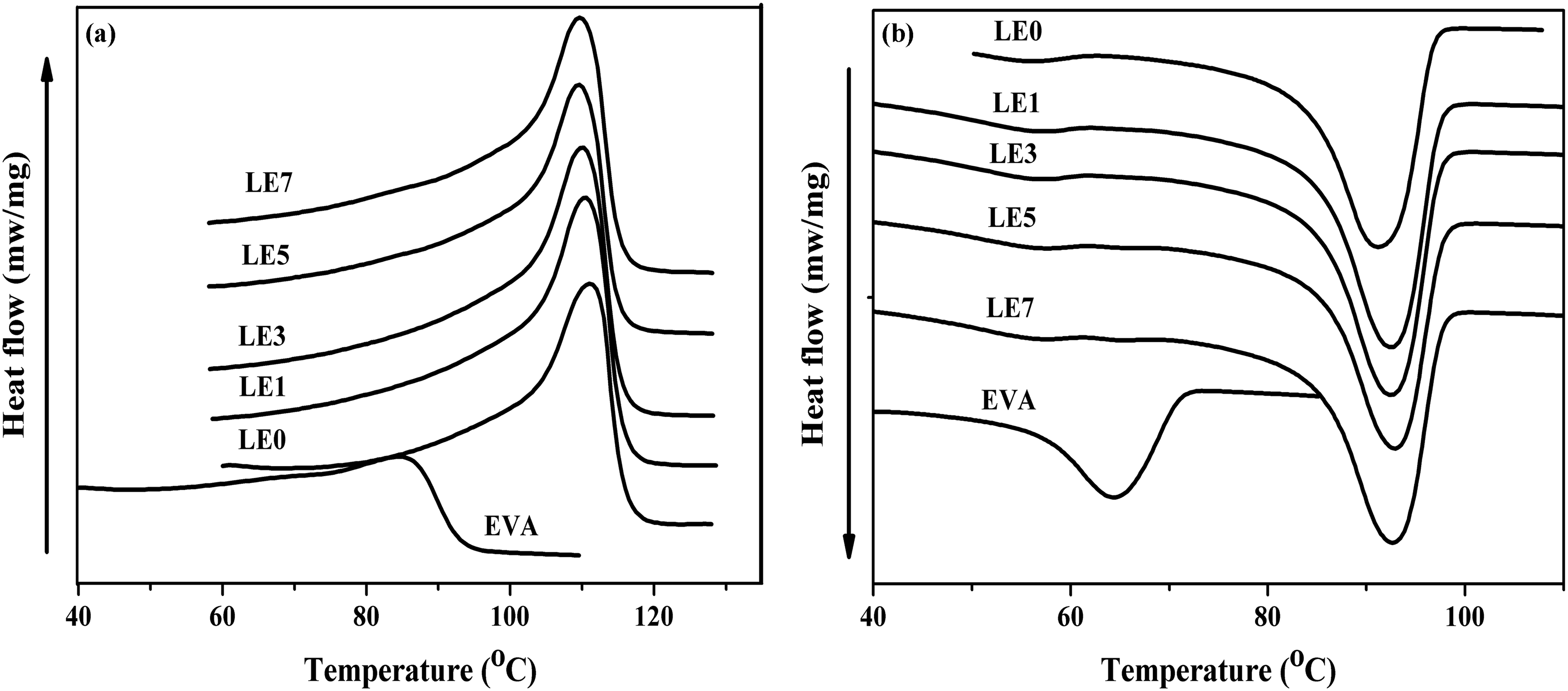
Melting and crystallisation curves of LDPE/EVA blends: a melting; b crystallization
Phase behaviour analysis
By knowing that there is no selective extraction method for UHMWPE phase near the LDPE phase from one side, and in order to be able to observe the real morphology of LDPE/UHMWPE blends, the SEM images for LDPE/UHMWPE blends were taken from cryofructured surfaces without any extraction. However, extraction of EVA phase was applied for LDPE/EVA blends.
SEM images (Fig. 3a–c) clearly indicated that the LDPE/UHMWPE (LU10, LU30 and LU40) blends have a two-phase morphology (sea island structure), showing the immiscibility of the used LDPE and UHMWPE in the study composition ranges. Combined with the DSC results, we concluded that although the LDPE/UHMWPE blends were miscible in the melt state, because of different rates of crystallisation between LDPE and UHMWPE, there were multiple melting peaks and phase separation in the SEM photos. Increasing UHMWPE content from 10% to 40% increases the average diameter of the dispersed UHMWPE domains from ∼20 to 70 μm. In addition, the dispersed particle size for LU40 blends is larger with broad size distribution than those observed in LU10 and LU30 blends.
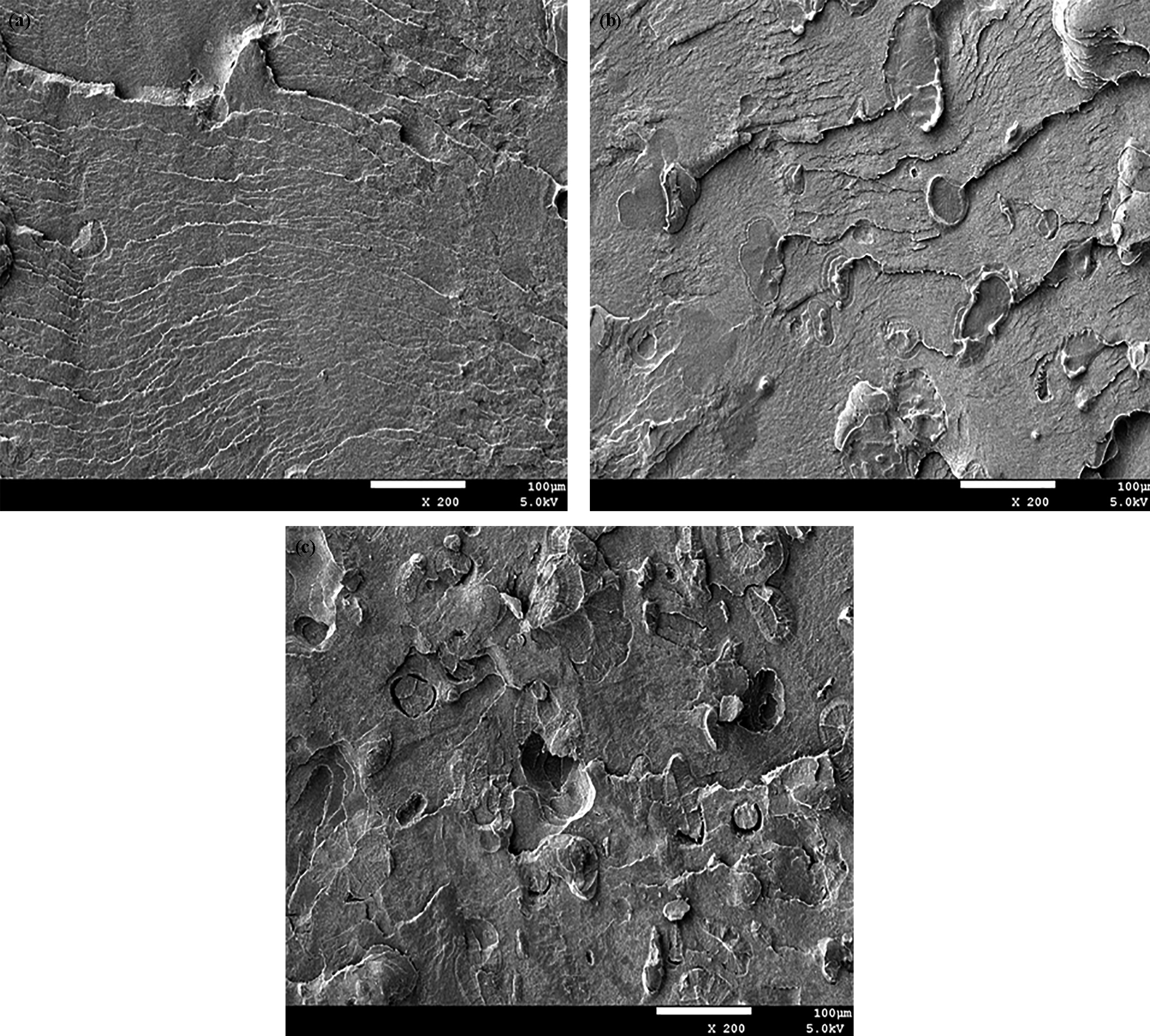
SEM images of LDPE/UHMWPE blends: a LU10; b LU30; c LU40
Figure 4a and b shows the obtained SEM images for blends containing various amounts of EVA (LE3 and LE7). SEM images clearly indicated that the LDPE/EVA blends with different compositions have a two-phase morphology that is similar with LDPE/UHMWPE blends, showing the immiscibility of the used LDPE and EVA in the composition ranges studied. Increasing EVA content from 3% to 7% increases the average diameter of the dispersed EVA domains from ∼0.24 to 0.48 μm, which is much smaller than UHMWPE domains in LDPE/UHMWPE blends. Since the dispersed EVA domains in LDPE/EVA blends are much smaller than UHMWPE domains in LDPE/UHMWPE blends, the addition of EVA can form a similar structure with LU40.
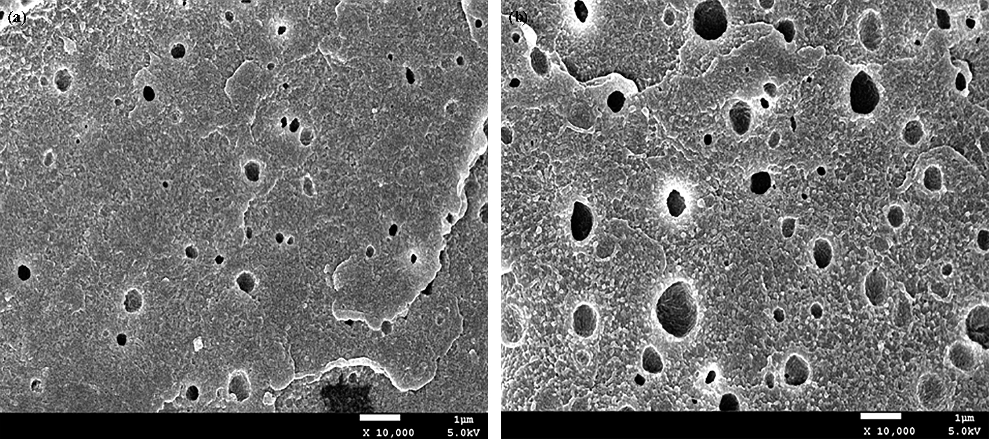
SEM images of LDPE/EVA blends: a LE3; b LE7
ESC experiments
The ESCR test was carried out at the temperature of 50°C. The time to failure of different samples is shown in Table 1. The time to failure is defined as the time when 50% of the samples failed during the ESCR test suggested by ASTM D1693. In most of the cases, cracking starts on both sides in a direction perpendicular to the notch, and these small cracks grow and lead to catastrophic failure. However, LU40 and all the LDPE/EVA blends did not fail even for 1000 h. Combined with the above analysis, the reason maybe that due to the high impact resistance and high ESCR of UHMWPE and EVA phase, craze initiation and crack growth are likely to be prevented.
ESCR in terms of failure time of various blend compositions
Morphology analysis
After the ESCR test was completed, the failed samples were collected for further analysis of the crack surface by SEM. Two different sample morphologies were characterised: (i) fracture surface observation by the failed samples to obtain the morphology of the crack surfaces and (ii) cross-section view of ESC by microtome sectioning parallel to the crack direction.
It has been reported that the major factor to control ESCR property in the HDPE is the fibrillations, i.e. tie chain density.20–22 There have been many reports that the creep behaviour of process zone, that is, fibrillation within the process zone, can be a determining factor for ESCR properties of HDPE.
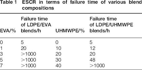
Figure 5a and b shows the SEM photos of the crack surfaces of LU10 and LU30. The size of fibrillation within the crack surface (traces of process zone during crack propagation) appears short. With increasing UHMWPE content, the size of fibrillation changed a little. However, considerable improvements were both produced when an UHMWPE weight fraction of 0.4 was used. Thus, the size of fibrillation was not the major determining factor for ESCR of the samples. Since LU40 and all the LDPE/EVA blends did not fail in the test, we did not study the crack surfaces of them. Furthermore, the cross-section view of ESC by microtome sectioning parallel to the crack direction was analysed.
SEM photos of crack surfaces of failed samples: a LU10; b LU30
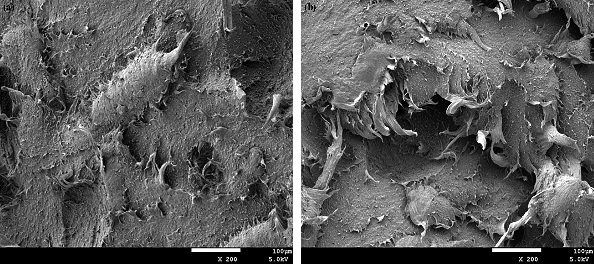
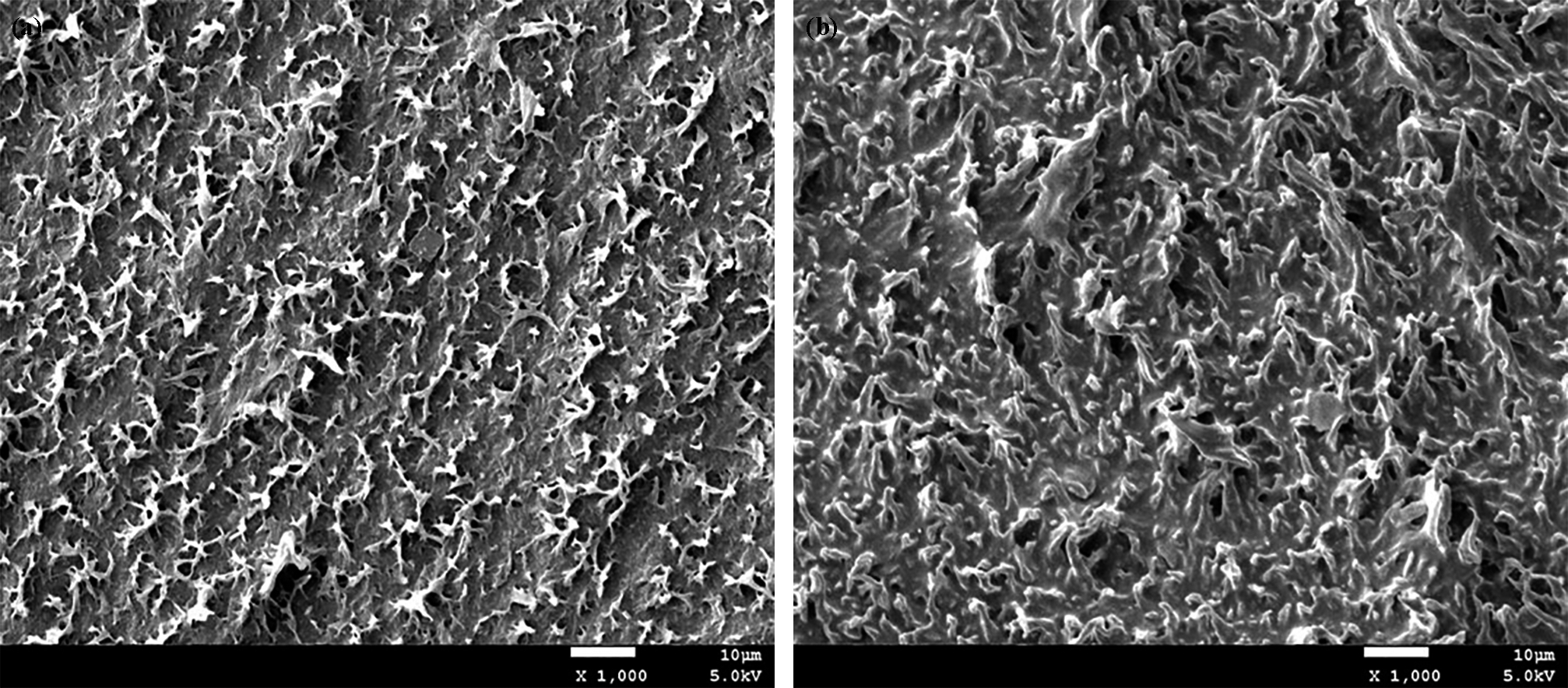
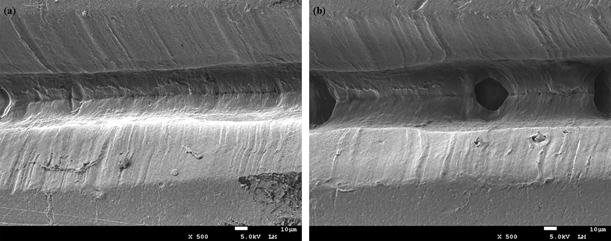
Figures 6a and b and 7a and b are high magnification pictures of the region parallel to the crack direction at different hours (10 and 1000 h) for samples LU40 and LE3 respectively. In the figures, voids are seen to have formed but the material has not been drawn enough to cause failure. In addition, the voids in LE3 are much smaller than those in LU40.
SEM photos of crack surfaces of failed samples: a LE0; b LE1
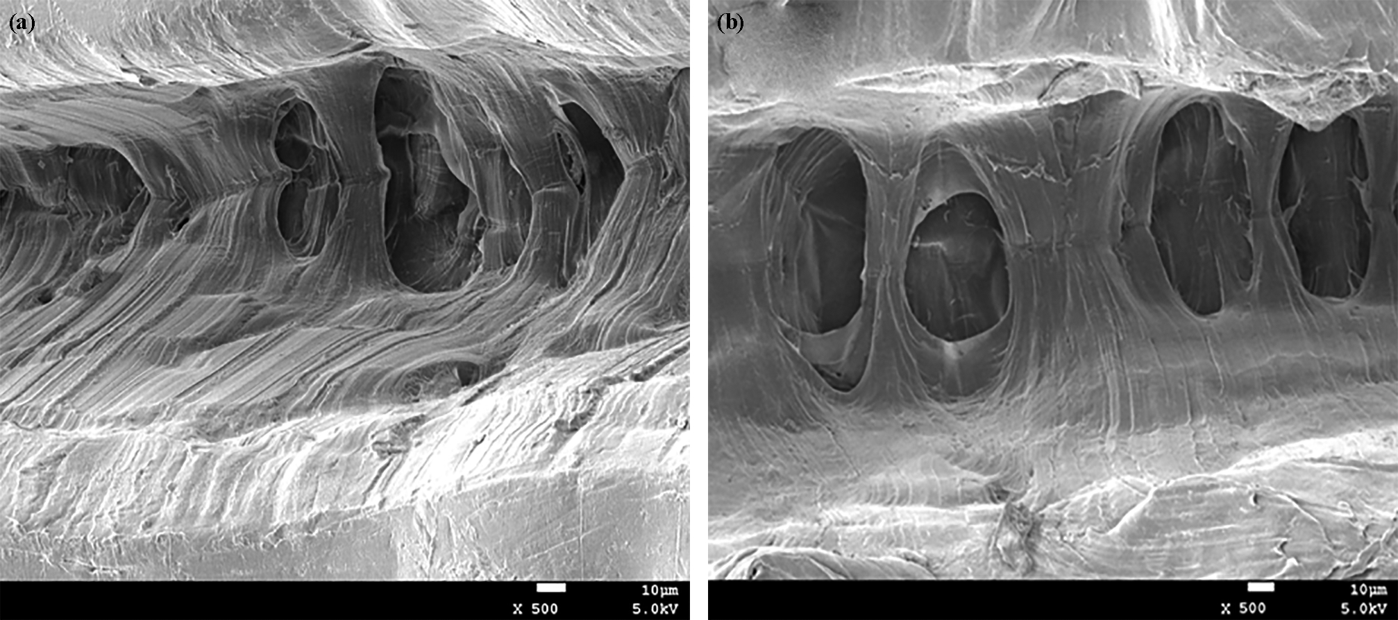
SEM photos of region parallel to crack direction at different hours for sample LU40: a 10 h; b 1000 h.
As discussed above, LU40 and all the LDPE/EVA samples surprisingly did not show failure during the ESCR test at 50°C. This detachment of the UHMWPE phase or EVA phase from the LDPE matrix is probably due to the influence of the ESCR. Under external stress, stress concentration and stress that is increased additionally by superposition of local stress fields are built up between the particles.9, 23 Owing to stress concentration and the formation of shear bands, higher hydrostatic stress is generated inside the particles, giving rise to cracking and formation of microvoids inside the blend. The result is a higher local stress concentration between the particles. There is an effect influencing crack propagation. Cracks, which enter the elongated microvoids, are rounded at their tips. These cracks are prevented from further propagation.
Mechanical properties analysis
The comparison of the mechanical properties of the two series blends was shown in Figs. 9–11. As was analysed above, the melt mixing LDPE/UHMWPE blend exhibited approximately equiaxed domains, which were formed by UHMWPE and were non-uniformly distributed throughout the whole system. Thus, with increasing UHMWPE content, the tensile strength decreased slightly, while the elongation at break decreased. For the LDPE/EVA blends, due to the small dispersed EVA phase and a high compatibility between LDPE and EVA, with increasing EVA content, the elongation at break slightly decreased, while the tensile strength increased. It was known that the UHMWPE showed a higher flexural modulus and yield stress than did LDPE. Thus, with increasing UHMWPE content, the yield stress and flexural modulus increased for the LDPE/UHMWPE blends. For the LDPE/EVA blends, with increasing UHMWPE content, the yield stress and flexural modulus decreased.
SEM photos of region parallel to crack direction at different hours for sample LE3: a 10 h; b 1000 h
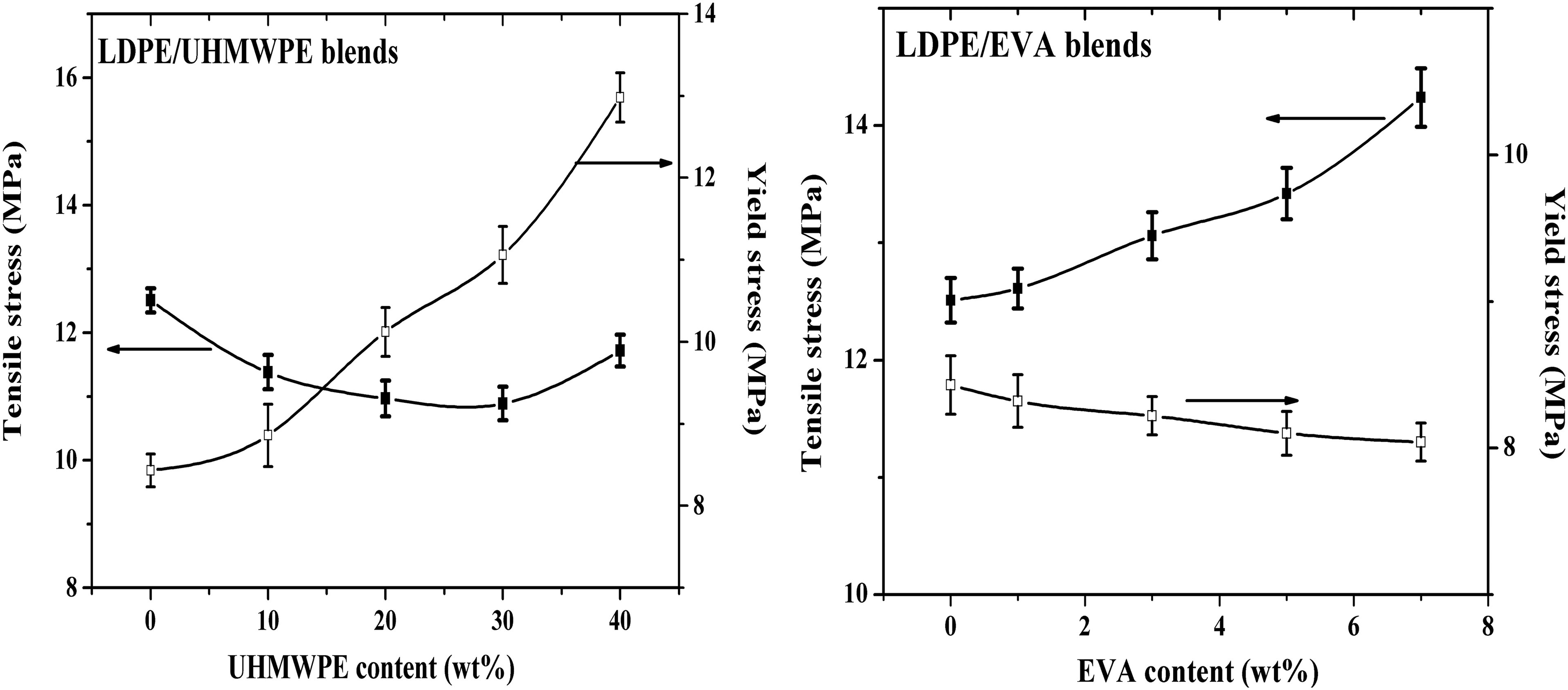
Comparison of yield stress and tensile stress of LDPE/UHMWPE and LDPE/EVA blends
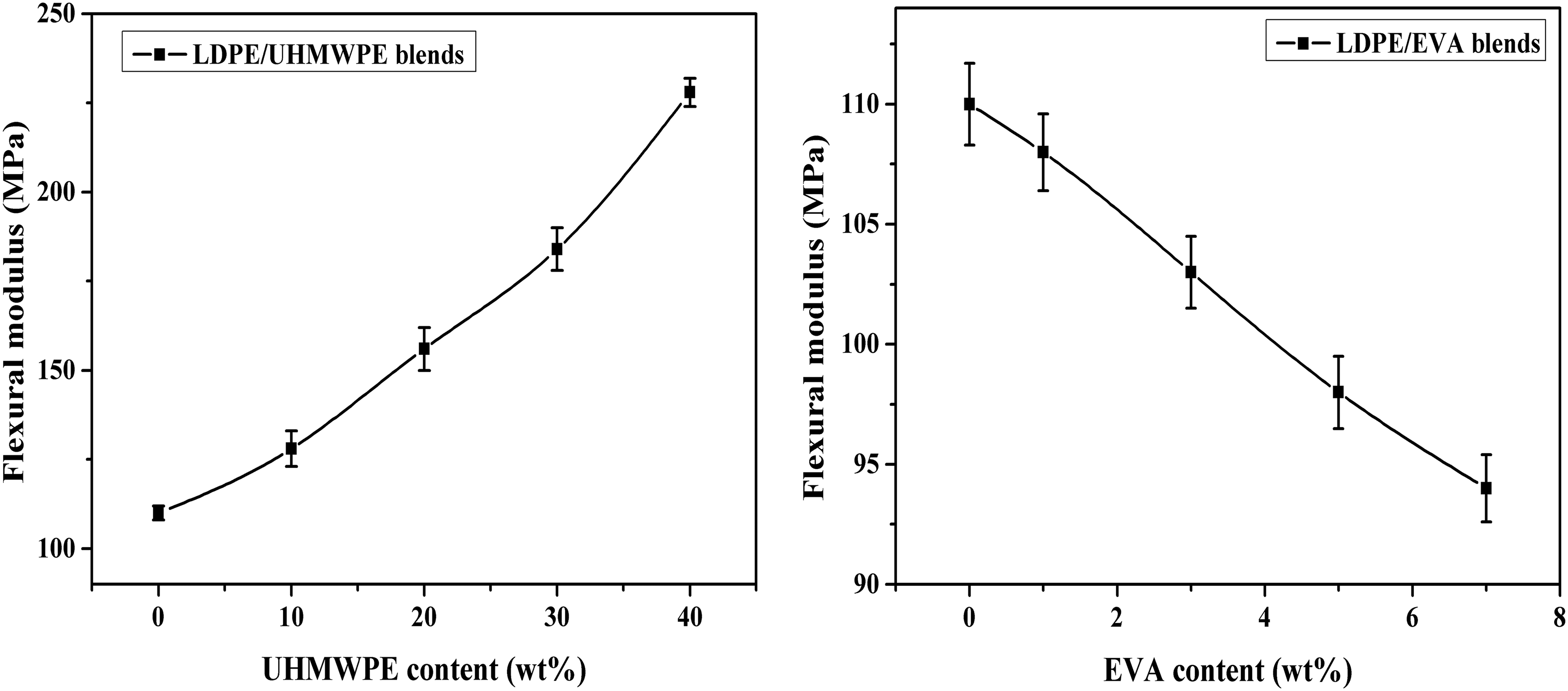
Comparison of flexural modulus of LDPE/UHMWPE and LDPE/EVA blends
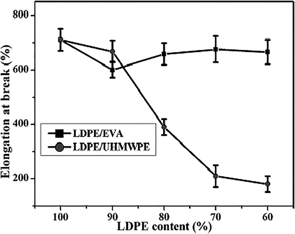
Comparison of elongation at break of LDPE/UHMWPE and LDPE/EVA blends
Conclusions
In this study, the ESCR performance of LDPE/UHMWPE and LDPE/EVA blends was determined. Although the LDPE/UHMWPE and LDPE/EVA blends both showed sea island structure, surprisingly, sample LU40 and LDPE/EVA blends did not show failure during the ESCR test. The morphology analysis showed that the sea island structures of LDPE/UHMWPE and LDPE/EVA blends, i.e. the UHMWPE or EVA particles, were capable of stopping crack propagation, which would improve ESCR values significantly. Since the dispersed EVA domains in LDPE/EVA blends were much smaller than UHMWPE domains in LDPE/UHMWPE blends, addition of EVA can form a similar structure with LU40. In addition, the LDPE/UHMWPE blends showed a higher yield stress and flexural modulus than did LDPE/EVA blends.
Acknowledgements
The authors would like to thank the National Natural Science Foundation of China (grant nos. 50903049 and 51273118), Provincial Science and Technology Pillar Program of Sichuan (China; grant no. 2013FZ0006) and Fundamental Research Funds for the Central Universities of China (Youth Foundation of Sichuan University; grant no. 2015SCU11008) for financial support and the Analytical and Testing Center of Sichuan University for providing measurements.