
Abstract
Extreme complexity in the range of polymer composition in waste printed circuit boards (WPCBs) will leave us to follow a series of steps to formulate an efficient recycling system. The current study deals with the recovery and utilisation of non-metallic fractions from WPCBs through dismantling, size reduction and sieve analysis. Density based techniques have been adopted in the current studies to separate the non-metallic fractions from metallic one due to its simplicity and cost effectiveness. The non-metallic fractions are quantified through sieve analysis and are utilised as reinforcing filler material in polypropylene matrix. Composite material with WPCBs has been prepared via melt blending techniques and is subjected to mechanical, thermal and morphological analysis to investigate its feasibility for automobile application.
Keywords
Introduction
The rapid growth in information and technology during the last few decades results in the generation of huge amount of obsolete electronic scraps. Recycling of these materials after end of life is essential to find out an effective solution to resolve the environmental pollution issue. Again, waste printed circuit boards (WPCBs) are considered as a hazardous waste material in the waste stream of waste electrical and electronic equipment (WEEE), which needs skilled technology to recycle. The literature survey suggests that printed circuit board (PCB) content in WEEE stream is ∼3% of the total waste, but their recovery and utilisation are difficult due to its complexity and presence of metallic element. 1 Although recovery of metal (Cu, 16%; Sn, 4%; Fe, 3%; Ni, 2%; Ag, Au, Pd and others in trace amounts) from WPCBs has already been taken care by various recyclers due to its high value, non-metallic fraction has been considered as an unwanted part. 2 Thus, to recover non-metallic fractions, WPCBs were being burnt in open air or sent to landfills, which causes removal of toxic gases and leaching of toxic elements to the environment.3, 4 Development of methodologies for the recovery of non-metallic fraction (thermoset resins, glass fibres, cellulose paper, etc.) from WPCBs is essential in the current scenario for a cleaner and safer environment.5, 7
Recovery and utilisation of WPCBs need a series of technical process to formulate an efficient recycling system. Figure 1 depicts the schematic representation of different steps followed in the present work. The recycling process starts from dismantling and pretreatment process followed by size reduction. During the dismantling step, the extraneous components attached to the PCBs are removed, and bare boards are crushed into smaller pieces, which were further divided into fine parts using mechanical shredders, granulators, cutting mills and centrifugal mills. 8
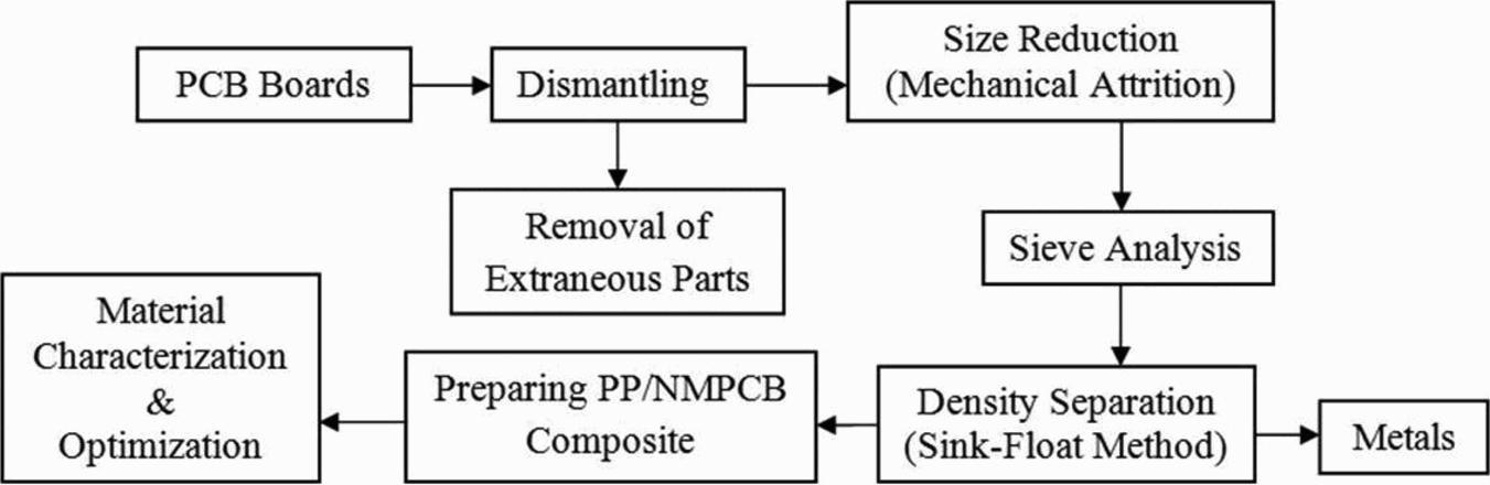
Printed circuit board recycling system
Physical method of separation has been taken into consideration in this study, which includes size reduction and density separation method depending upon the properties of the constituent materials. Organic solution of density of 1.8 g cc− 1 is prepared using zinc chloride (ZnCl2) solution, as it was found that density of WPCBs is much lesser than its metallic counterpart. The density of non-metals found to be in the range of 1–1.8 g cc− 1 and metal starts from 2.7 g cc− 1 (Al), thus allowing the material to separate in a better way.
Recovered non-metallic fractions can be used for building materials like modified asphalt, cement mortar and concrete members, main materials for making compound boards and filling materials in polymer composites. Utilisation of this material has also many advantages like abundance of raw materials, production simplicity and low cost with environment friendly approach.9–14
Materials and methods
Dismantling: preparing PCB powders and sieve analysis
In the first step, size reduction was performed through a cutting machine, followed by a Cryomil (Retsch, Germany) with a cycle time of 10 min and frequency of 20 Hz for better removal of metal and non-metal. After the end of each cycle, the powders were sieved in a sieve shaker (LYNX SS Gyratory Motorised LM-17-596) for separation and recovery of non-metallic fraction.
Sink float method for metal separation
The pulverised samples are then separated using density column using an organic solution of predetermined density. The list of various liquids available as a sink float media is represented in Table 1, which may be adjusted by adding a suitable solvent. The effectiveness of density separation process was also influenced by the size of particles present in the PCB powder. The experimental studies indicate that Cu particles are more effectively separated at 149 μm size. On the other hand, Si particles are more effectively separated at the size of 74 μm. Thus, the results obtained from density separation methods confirmed the relationship between the particle size and effectiveness of metal removal as represented in Table 2.
Densities of various heavy liquids
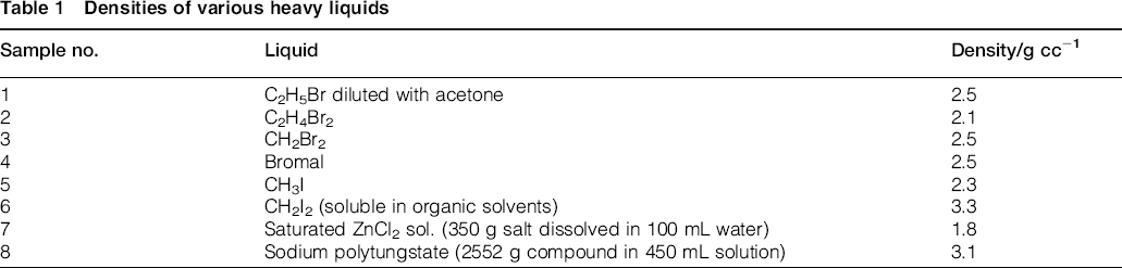
Sieve analysis and density separation
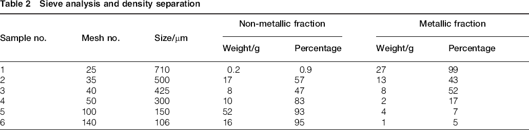
Zinc chloride solution was taken into consideration in the current study due to its low cost and recyclability. ZnCl2 is a colorless crystalline material with a density of 2.907 g cc− 1, which is highly soluble in water, alcohol and acetone. The experimental steps followed for the separation of non-metallic fraction from the metallic one is represented in Figs. 2 and 3; similar studies have also been carried out by Eswaraiah et al. 6
a crushed PCB; b extraneous parts; c sink float bath; d metals from magnetic separation; e ground PCB powder (425 μ); f non-metals (710 μ); g metals (710 μ); h metals (500 μ); i metals (425 μ)Sieve analysis and density separation
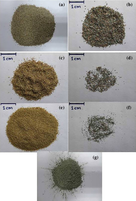
a non-metal (300 μ); b metals (300 μ); c non-metals (150 μ); d metals (150 μ); e non-metals (106 μ); f metals (106 μ); g PCB filler (>106 μ)Sieve analysis and density separation
The polypropylene (PP) material was procured from Haldia Petro Chem. Ltd (grade, M110). The fine powders below 100 μm were taken into consideration, as metal content at this level was found to be negligible as represented in Table 2. An optimised composition of PP/PCB composite was prepared by melt mixing technique using a twin screw microcompounder (XPlore, 15 mL, DSM, The Netherlands) followed by mechanical, thermal and morphological characterisation studies.
Testing and characterisation
Tensile and impact specimens were prepared as per ASTM D638 and ASTM D256 standard under processing temperature of 190°C, at 100 rev min− 1 and mixing time of 12 min to assure homogeneous dispersion. Tensile testing was performed with the help of a universal testing machine (UTM 3382, Instron, UK), and impact strength of notched specimens was measured using an impact tester (IT 504 Plastic Impact, 899 and Notch Cutter, Tinius Olsen, USA). All the mechanical tests were performed at room temperature, and the elongation at break was noted at a crosshead speed of 50 mm min− 1.
The thermal stabilities were studied through differential scanning calorimetry (DSC Q 20, TA Instruments, USA) and thermogravimetric analysis (TGA Q 50, TA Instruments, USA) respectively. Analysis by DSC was carried out using 5–10 mg of samples at a scanning rate of 10°C min− 1 with a temperature range of − 50 to 200°C under nitrogen atmosphere. Similarly, TGA of 5–10 mg samples were carried out from 50 to 800°C at a heating rate of 10°C under nitrogen atmosphere. Fourier transform infrared (FTIR) spectra were recorded using Nicolet 6700, USA. Each spectrum was obtained by adding 64 consecutive scans with a resolution of 4 cm− 1 within the range of 400–2500 cm− 1. Crystalline morphology of specimens in our work was studied using a well controlled hot stage polarised optical microscope (PLM DM 4500P, Leica, Germany). The thermal programme followed is represented in Fig. 4.
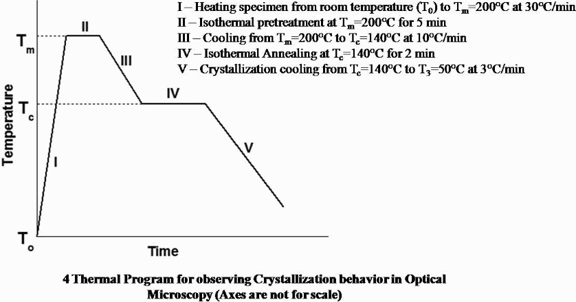
Thermal program for observing crystallisation behaviour in optical microscopy (axes are not for scale)
Results and discussion
Mechanical properties of PP/PCB composite
Mechanical properties of a particulate–polymer composite depend on the effectiveness of stress transfer between the matrix and filler. The strength of the composite material depends on two factors: one is weakening effect due to the stress concentration, and the other is reinforcing effect, where they serve as barriers to crack propagation. Further, the strength of the composite also depends on the interfacial adhesion among the filler and matrix and percentage of filler loading. Table 3 represents the mechanical properties of PP/PCB composite at different compositions. The results are in line with the results obtained by Ou et al. 15 A strong interfacial bonding between the matrix and fillers is required for effective stress transfer from the filler to matrix and vice versa to increase the strength of the composite. Thus, incorporation of 3 wt-% maleic anhydride grafted polypropylene (MAPP) to PP/10%PCB results increased mechanical properties as compared to the composite without any compatibiliser. This may be due to the improved adhesion between the filler and matrix in the presence of MAPP causing better stress transfer from the matrix to the particles.16–18
Mechanical properties of PP and PP/PCB composites
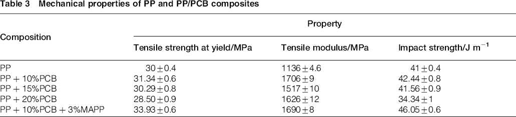
Further, the increase in stiffness (elastic modulus) with the addition of non-metallic PCB powder is attributed to higher rigidity of particles than that of the matrix.19, 20 This is due to the restriction of polymer mobility in the presence of fillers and deformation of matrix by introducing a mechanical restraint. A drastic increase of almost 50% in modulus has also been observed at 10 wt-% filler loading as compared to virgin PP. 16 However, incorporation of 3 wt-%MAPP in optimised PP/10%PCB sample results poor tensile modulus, which shows the indirect effect of matrix crystalline structure modified in the presence of compatibiliser. 21
Polypropylene/PCB composites have shown improved toughness as represented in Table 3. This improvement is attributed due to the crack deflection around the filler particles with higher dissipation energy at the damage zone. Further, toughening mechanisms are thought to be associated with the debonding of non-metallic particles, which prevents crazing of polymer matrix. Further, treatment of PCB filler with MAPP induced crack deflection towards the poles of the particles allowing propagation through the matrix material. This process consumes more energy, indicating higher impact strength due to increase in the crack length.
Fourier transformation infrared spectroscopy
The formation of interfacial bonds in the system was further studied using FTIR spectroscopy. Figure 5 depicts the FTIR curves for PP/10%PCB composite samples with untreated and treated filler. It is evident that the backbone molecule of polyolefin represents a strong peak of (–C–H) corresponds to 2950 and 1455 cm− 1 with a moderate peak of (–CH2–) at ∼720 cm− 1. Methyl groups (C–CH3) also represent a significant peak at 2850 cm− 1. The characteristic adsorption peak at 1710 cm− 1 observed in PP/PCB/MAPP composite is attributed to the stretching vibrations of C = O group of MAPP confirming the presence of ester linkage at the interface. This clearly supports the stronger interaction between filler and matrix, which is presumably responsible for the improved mechanical properties of the polymer composites.
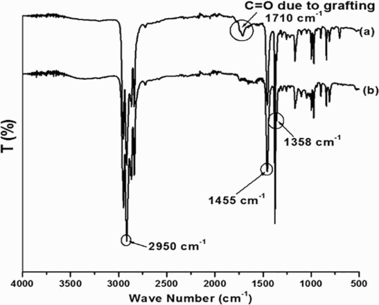
Fourier transform infrared spectra of a PP/PCB/MAPP and b PP/PCB composites
Thermal analysis
Differential scanning calorimetry
Figure 6 shows the heating and cooling curves of DSC analysis of PP and PP/PCB and PP/PCB composites in the presence of MAPP. The melting temperature Tm of PP and PP/PCB at 10 wt-% filler loading is taken as the maximum of the endothermic peak from the second heating, whereas the crystallisation temperature Tc is taken as the maximum of the exothermic peak from the cooling cycle. It is evident from the figure that there is no such deviation in melting transition of PP and PP/PCB composites. However, with respect to crystallisation temperature, PP indicates Tc at 109.7°C, whereas PP/PCB composite in the presence of 3 wt-%MAPP shows Tc at 125°C, which may be attributed due to the presence of PCB powder restricting the chain mobility of the matrix materials. This also suggests improved adhesion between the fillers and matrix contributing to a faster crystallisation during cooling.22, 23 Further, the nucleating effect of the filler improves fine crystalline structure of PP matrix, which in turn gives better mechanical properties. 24
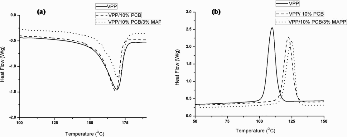
Differential scanning calorimetry of a heating and b cooling thermograms
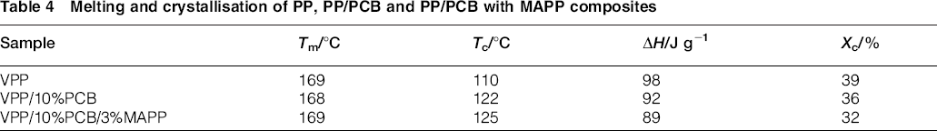
The same has been confirmed using optical microscopy displayed in Fig. 7. It is evident from Fig. 7 that incorporation of PCB powder within the polymer matrix acts as nucleation agents in the PP matrix during crystallisation of PP/PCB composites owing to strong interaction between fillers and matrix polymer. Further, the heterogeneous nucleation effect of the fillers reflects towards limited space leading to smaller size of crystals. In addition, these nuclei centres will also cause more crystalline defects and confine movements of polymer chains producing stress in the crystals. Every filler particle initiates more number of nucleation sites; thus, nucleation density is also significantly increased. This pursues the formation of enormous number of spherulites with restricted size due to the surrounded spherulites (Table 4).25–27
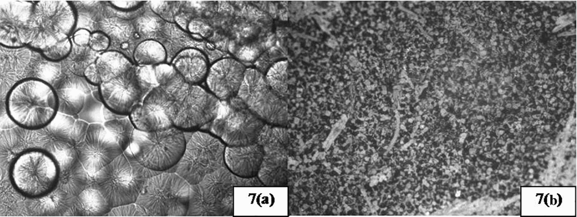
Optical micrographs of spherulite formation in a virgin PP and b PP/PCB/MAPP
Melting and crystallisation of PP, PP/PCB and PP/PCB with MAPP composites
Thermogravimetric analysis
Thermogravimetric analysis thermograms of virgin PP, PP/PCB and PP/PCB with MAPP are represented in Fig. 8. It is evident that the thermal degradation of virgin PP starts at 275°C and 100% degradation are noticed at 410°C. However, non-metallic PCB powder being a cross-linked polymer starts degradation at higher temperature. Thus, the combination of these types of filler with polymer matrix improves the thermal stability creating a protect layer to reduce the evaporation of polymer matrix. 28 This may also be explained due to strong interaction between the polymer and filler surface through chemical linkage in the presence of a compatibiliser. The PCB powder delays volatilisations of the composite material generated at the temperature of carbon–carbon bond scission of the polymer matrix.
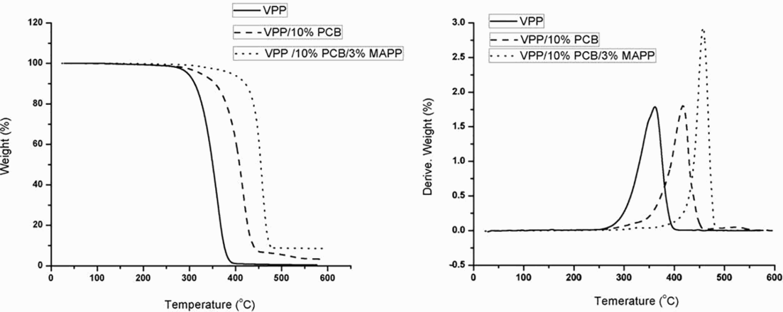
a weight loss (%); b derivative weight loss (%)Thermogravimetric analysis thermograms
Morphological studies (scanning electron microscopy)
The morphology of the impact fractured surfaces of PP and PP/PCB composites with and without MAPP is depicted in Fig. 9. Figure 9a reveals pullout surface with wide gaps between the filler and polymer matrix in the case of PP/PCB composites without MAPP, whereas in the presence of a MAPP compatibiliser, the fillers are well coated and embedded within the PP matrix. This indicates poor interfacial adhesion of PP/PCB composites without MAPP, which may be due to a large difference in the surface energies between the fillers and the matrix. Maleated polypropylene acts as a cohesive coupling agent between the filler and matrix introducing efficient filler–matrix adhesion. Figure 9 also reveals that the compatibiliser is adhered to the wall of the PCB powder, where the crack propagation has not been initiated because of filler–matrix adhesion. Further, it is also noticed that composites with compatibiliser exhibit smoother surface indicating better dispersion of filler within the polymer matrix.
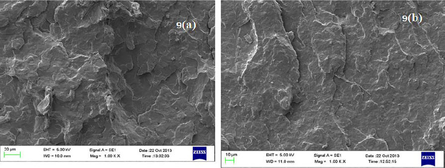
Images (SEM) of fracture surface of a VPP/10%PCB and b VP/10% PCB/3%MAPP
Dynamic mechanical properties
Storage modulus
Figure 10 represents the temperature dependencies of the dynamic storage moduli E’ of PP matrix in the presence of PCB and MAPP compatibiliser. The results indicate improved storage modulus for VPP/10%PCB composites as compared to the virgin matrix. The improvement in storage modulus of the composites with the pristine counterpart is more prominent in the rubbery region because, in this region, the material is soft and flexible. The enhancement in the storage modulus strongly depends on the aspect ratio of dispersed particles and intercalation of the polymer chains inside the polymer matrix. 29 Furthermore, restricted segmental motion at the interface may be the possible reason for a phenomenal increase in storage modulus.
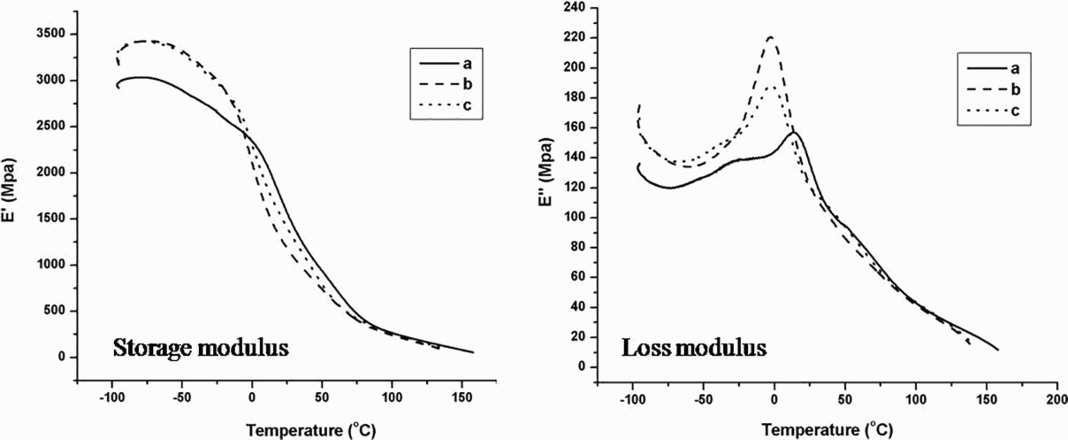
Storage and loss modulus of a VPP, b VPP/10%PCB and c VPP/10% PCB/3%MAPP
Loss modulus
Figure 10 indicates the dynamic loss modulus of virgin PP and its composites. The loss modulus E” of the composite materials displays a maximum peak at around − 18°C, related to the β transition, which corresponds to the glass transition temperature of PP. The glass transition is assigned to the energy dissipation possibilities across the free amorphous phase, and the lower Tg values would mean an easier mobility of the free amorphous phase in the composites. The comparison study of PP with PP/PCB composites indicates a shifting of peak value, which can be attributed to the immobilisation of polymer molecules near the surface of PCB powder. Conversely, the filled composites display an increase in peak height and broadening of the relaxation region. This behaviour is probably due to inhibition of the relaxation process, resulting in the decrease in the mobility of polymer chains in the crystallites.
Conclusions
The PP/PCB/MAPP composites were successfully prepared via melt intercalation technique. Non-metallic powder obtained from PCBs has better capability to act as a better reinforcing agent within polymer matrix. The finding also suggests an ecofriendly and cost effective approach to reuse the waste non-metallic PCBs within PP. Further, we find that, with the incorporation of 10 wt-% non-metallic PCBs and 3 wt-%MAPP in PP increases the tensile strength, tensile modulus and impact strength to 13, 50 and 12% respectively, as compared to virgin PP. The melting, crystallisation and degradation temperatures were significantly increased in both PP/PCB and PP/PCB/MAPP composites, indicating good nucleation of filler and excellent adhesion between the filler and matrix. The dynamic mechanical analysis results revealed a considerable increase in the storage modulus (stiffness) and change in the glass transition temperature as compared to polymer matrix, indicating as an alternate material to mineral filled composite for automobile application.