
Abstract
To provide an accurate prediction of mode II delamination properties of stitched composites, a single stitched laminate under pure shear load (interlaminar shear) is investigated. An interlaminar shear test (IST) is conducted, using a specially constructed fixture. A finite element model of the IST is developed, using a spring connector to represent the stitch thread. Furthermore, an end notch flexural test is simulated based on the IST model and with a cohesive zone element used to simulate crack propagation. The effects of the cohesive zone modelling parameters (interfacial strength, stiffness and viscosity coefficient) are also investigated. Close agreement is obtained between the simulated and experimental results. Finally, the verified model is extended to study the effect of the number of stitch rows in the crack region. The results confirm that the crack propagation starting point (peak load) depends on the number of stitch rows in the crack region.
Keywords
Introduction
In many applications of composite laminates, delamination is the main mode of failure because of the weakness of laminates in the thickness direction. To suppress the growth of delamination, three-dimensional reinforcement techniques have been developed, such as z-pinning, 1 stitching, 2 knitting, 3 braiding3, 4 and weaving.3, 5 Stitching involves the insertion of threads into the preforms in the thickness direction. The threads are inserted before resin infusion and consolidation. It has been reported that stitching significantly increases the delamination resistance under modes I6–8 and II.9–12
Prediction of the delamination behaviour of stitched composites using finite element simulation has attracted much attention. In particular, Chen et al. 13 predicted the effective energy release rate of stitched composites under mode II loading using a J integral contour. The interaction of a stitch with the surrounding laminates was idealised as an elastic–perfectly plastic relationship and represented by very short bar elements in a three-dimensional finite element model. It was concluded that the effective energy release rate depends strongly on the crack length and the number of stitches in the bridging zone. However, the predicted energy release rates were not compared with experimental data. Another numerical study was reported by Wood et al. 11 who used a method called the virtual crack closure technique (VCCT). A stitch was modelled as a spring–damper system composed of three connected rods. A numerical parametric study was conducted to obtain the force–displacement relationship for single stitched laminates under pure shear loading. The stitch thread and matrix properties were taken as input. This parametric study also considered stitch failure at the surface loop, so the frictional force of thread pullout was taken into account. The predicted energy release rates were close to those determined experimentally (with an error < 9%).
During the last two decades, the use of the cohesive zone model (CZM) to simulate damage in composite materials has expanded rapidly. Compared with VCCT, CZM can predict both damage initiation and propagation, whereas VCCT can only be used to simulate damage propagation. Therefore, CZM has become widely used to simulate not only all the modes of delamination testing14–16 but also composite structures (e.g. π and T joints17, 18), damage in open hole testing19, 20 and many other situations.
The aim of this paper is to develop a finite element model of mode II delamination testing of stitched composites based on the CZM. The work involves three steps. First, an experimental and numerical study of single stitched laminates under pure loading is conducted. Second, the end notch flexural (ENF) test simulation is modelled based on a single stitched laminate model in combination with CZM, and the results are validated by comparison with previous experimental results. 12 Because there is no consensus regarding the choice of CZM parameters for ENF modelling, parametric studies of cohesive zone properties are also conducted. Finally, the validated model is extended to investigate the limitations of previous experimental work, where there was only one stitch row in the crack region (before testing). The effect of additional stitch rows in the crack region is also addressed numerically.
Interlaminar shear test of single stitched specimens
Experimental method
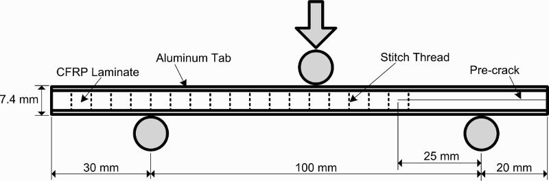
The specimens for the interlaminar shear test (IST) were cut according to the dimensions shown in Fig. 1a. The laminates contained 24 plies of quasi-isotropic (+45/0/ − 45/90)3S with Kapton film in the middle layers. The laminates were made with carbon fibres (T800SC-24K, Toray Industry) and epoxy (XNR/H6813, Nagase Chemtex Corp.) as the matrix. Vectran (Kuraray) was used as the stitch thread, with a fibre linear density of 500 denier (equivalent to 0.0394 mm2 cross-sectional area). The details of the manufacture of the laminates have been described previously. 12 It is worth noting that the single stitch was in the stitching environment (connected with other stitches). The other eight stitch threads where located at all of the edges had already been cut in the middle layer using a sharp, thin razor. Similar conditions have been used in interlaminar tension testing to avoid sudden pullout of the stitch thread during the test. 21 Because there is no standard testing fixture for this specific application, a special jig was designed to be fitted with a standard Iosipescu fixture as shown in Fig. 1b. The specimen was held by the special jig and placed in the Iosipescu fixture, before being tested using a tensile test machine (Instron 4505 series). A small load cell (10 kN) was used, with a crosshead speed of 0.025 mm min− 1. The tests were conducted until the stitch thread broke.
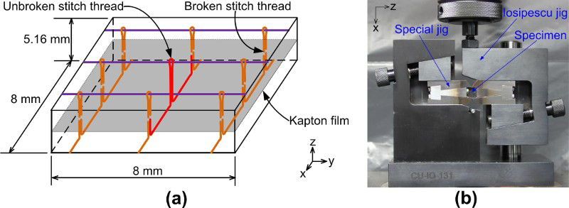
a specimen geometry; b experimental set-up
Simulation of IST of single stitched specimens
To simulate the ENF test, the IST of a single stitched specimen was first modelled and verified. Finite element modelling was conducted using ABAQUS commercial software. The stitch thread was modelled as a spring connector with a user defined force–displacement relationship. The spring was connected to the laminates through multiple point constraints (MPCs). The size and shape of the connection points (the MPC area) were based on the stitch cross-sectional area as shown in Fig. 2. The stitches resembled composite materials containing two stitch threads (Fig. 1a) with epoxy resin as the matrix. Generally, the cross-sectional areas of the stitches were close to elliptical as a result of the compaction and pretensioning of the two threads during fabrication. The major and minor axes of the ellipse were measured from seven specimens.
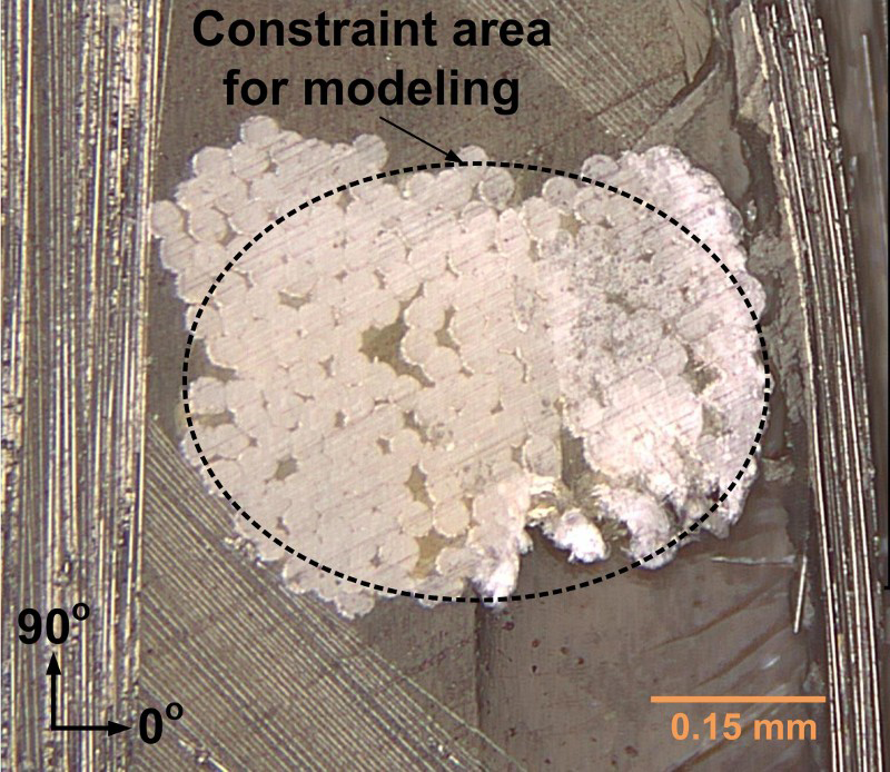
Cross-sectional of stitch thread composites at interface between 90° layers
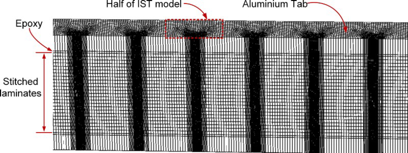
The geometry of the IST model is shown in Fig. 3. The area close to the interface with the MPC area was also modelled as an ellipse, with axis lengths and element sizes twice those in the MPC area. Taking account of the stress concentrations existing between the stitch thread and the surrounding laminates, the convergence of the element sizes was investigated. Several combinations of element sizes were simulated to check mesh convergence (Fig. 4).
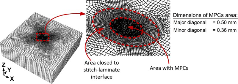
Half model (lower part) of IST specimen
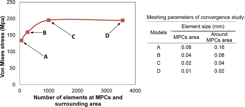
Convergence check of elements sizes
Each layer of laminates was modelled using continuum shell elements, with one element in each thickness of the layer. All of the layers were connected by sharing of nodes. Before computation, the element shape and compatibility errors were checked using the ABAQUS package. The laminae properties listed in Table 1 were used; they were calculated using in-house simulation codes based on the homogenisation method. 22 Input properties such as fibre and matrix properties were obtained from the manufacturers.
Mechanical properties of laminae

Simulation of tabbed end notch flexural (TENF) test
Mode II delamination tests of multidirectional stitched composites were conducted previously 12 . A TENF specimen was used to avoid matrix cracking in the loading area during the test (Fig. 5). Therefore, in this finite element simulation, the TENF test was modelled, rather than the ENF test. The modelling and meshing techniques for the laminates (including the stitched thread) from the IST simulation were adopted.
Tabbed end notch flexural experimental set-up (Herwan et al. 12 )
Additional aluminium tabs and adhesive bonding were connected to the laminates by node sharing. The crack propagation zone was modelled using cohesive zone elements with a traction separation response. The cohesive zone elements were inserted at positions where an actual crack occurred in previous experiments 12 (at the interface of the − 45/0 layers, on the compression side). To select appropriate parameters for the cohesive zone elements, a parametric study was conducted. These CZM parameters were the initial interface stiffness K0, the interface strength σi and the viscosity coefficient μ. Zhao et al. 14 have summarised typical values of K0 and σI,II obtained by many investigators through trial and error methods (in many types of application). It seems that most investigators have preferred to use an initial stiffness between 1012 and 1015 N m− 3. Values that are too large can create unexpected oscillations, while values that are too small can give unreasonable compliance of the models.
Unlike interface stiffness, there is no specific suggested value for interface strength. Some results indicated that lower values can help computational convergence, but extremely low values can affect accuracy.
23
Computational convergence has become a serious problem in simulation of mode II delamination tests. To overcome this, viscous damping techniques are commonly used.
24
The optimal viscosity coefficient should be determined, taking account of the computational costs and the effect on the accuracy of the results.
25
In the present work, various values of K0,
 and μ were tested, and an appropriate value of each parameter was then recommended.
Furthermore, a quadratic stress failure criterion was applied to evaluate the initial damage according to the following equation
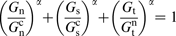
 (i = I, II, III) are respectively the stress components and the critical interfacial strength under pure modes I, II and III.
Delamination growth was controlled by an exponential softening fracture based method. A mixed mode fracture energy criterion with power law interaction was applied according to the following equation
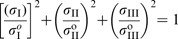
The normal critical strain energy release rates
 and shear critical strain energy release rates
 , and
, and
 were 450 and 880 J m− 2 respectively, which were obtained from previous experiments.8, 26 The value of α was assumed to be 1. To reduce the simulation time, a half slice model was used instead of the full model. Each half slice was equal to one-sixteenth of the full model and consisted of only half of the stitch thread in the width direction, as shown in Fig. 6. The symmetric boundary condition was applied at the side where the half stitch was placed.
Tabbed end notch flexural modelling geometry
Another issue that has to be addressed in modelling stitched multidirectional laminates is the interaction between the stitch and matrix for different layer orientations. The interlaminar shear tests of a single stitch in the previous section were conducted with the crack between the 90°/90° layers. In this case, during the test, the stitch penetrates the surrounding laminates in the x-direction (Fig. 1a, b), which is perpendicular to the 90° layer (Fig. 2). The force–displacement curve of a single stitch will be different if the stitch penetrates the laminates with another orientation. To deal with this issue, the elastic modulus E of the elements in the vicinity of the stitch threads (Fig. 3) was varied, depending on the orientation of each laminate (at the position where the spring connector was applied). It was assumed to be 4.6 GPa (equal to E2 of the laminate), 2.8 GPa (equal to Ematrix of the matrix) and 3.7 GPa (the average of E2 and Ematrix) for the cases in which the spring was connected to the laminate with orientations of 90, 0 and 45° respectively. These adjustments of properties were applied only at those layers where a crack plane existed because the penetration of the stitch through the laminate was negligible at other layers.
Using similar techniques, the effects of the number of stitch thread rows on mode II delamination properties were investigated. It should be noted that this issue could not be investigated in previous experimental work, 12 where the TENF testing for a crack length a of 25 mm was conducted with only one stitch thread in the crack region (Fig. 5). The experimental work showed that the GIIC of stitched composites (at a = 25 mm) were even lower than the values for unstitched composites because of the increasing local fibre volume fraction in the stitched laminates. Several models with different numbers of stitch rows in the crack region were analysed, and a model of unstitched laminates was also presented for comparison.
Results and discussion
Experimental and simulated results of interlaminar shear test
Load–displacement curves of the IST from both experiment and simulation are plotted in Fig. 7a. The load increased almost linearly with increasing displacement until the stitch thread broke. An insignificant non-linear region appears in the experimental results between displacements of 0.1 and 0.2 mm. It is most probably due to bridging by in-plane fibres (90° layer). It appears that there lease film does not work properly inside the stitched laminates because the crack was not confined to the film interface (Fig. 7b). It should be noted that the release film was inserted into the preform before stitching and resin infusing. The film was in contact with the fibres under pretension during stitching, so the film surface could have been damaged and cease to be perfectly flat.
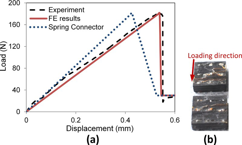
a load displacement curve of experimental and numerical results; b fracture surface of IST specimen
Furthermore, the fracture surface (Fig. 7b) also showed that the stitch broke at the midlayer where delamination occurred. It revealed that the frictional force between stitch thread and surrounding laminates could be neglected because of the absence of fibre pullout. The situation was different in the opening mode case, 27 where the stitch threads broke mostly at the upper side of the threads and the frictional force (after stitch breakage) played an important role in the energy release rate. In shear mode loading, the energy released by stitch bridging is mostly due to penetration of the stitch into the laminates, to plastic deformation of the stitches and to fractures.
The simulation result (Fig. 7a) was obtained from the model with element sizes 0.02 and 0.04 mm in the MPC area and the surrounding area respectively. These element sizes were selected for the single stitch model on the basis of the element convergence check (Fig. 4), where mesh independent results had already been obtained with these typical element sizes.
Figure7a also presents the relative displacement of the spring connectors. The relative displacement of the two endpoints of the spring connector was 0.11 mm shorter than the total laminate displacement. Physically, this could be considered as being due to the penetration of the stitch into the surrounding laminates by ∼0.06 mm on each side. It is also worth noting that the force–displacement curve of the spring connector (Fig. 7a) was the same as the input curve for the spring properties, which was adjusted to fit the results of the IST simulation.
Cohesive zone modelling parameters
The results of the parametric study of interfacial strength, viscosity coefficient and interfacial stiffness are plotted in Figs. 8–10 respectively. All of these figures show the load–displacement curves until the initial crack starts to propagate (indicated by the drop in load). Beyond this point, the simulation will run relatively slowly. Considering the computational time and the energy release rate calculation method, which were based on the peak load, 12 the simulations were stopped a few millimetres beyond the load drop point.
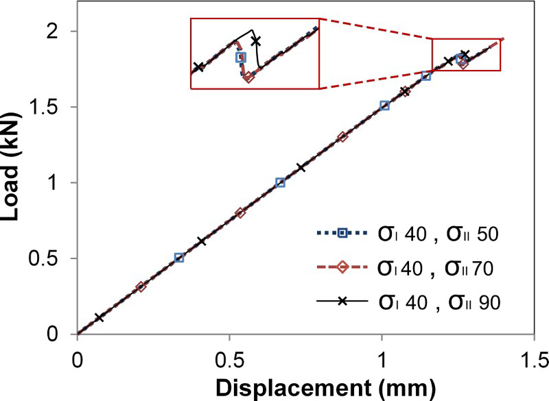
Effects of critical interfacial strength on results accuracy
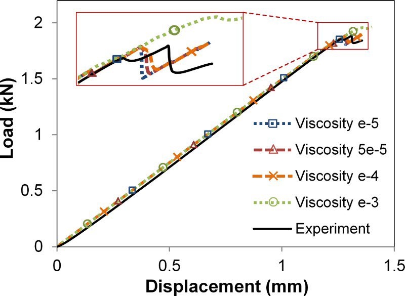
Effects of viscosity coefficient of cohesive element on change of peak load
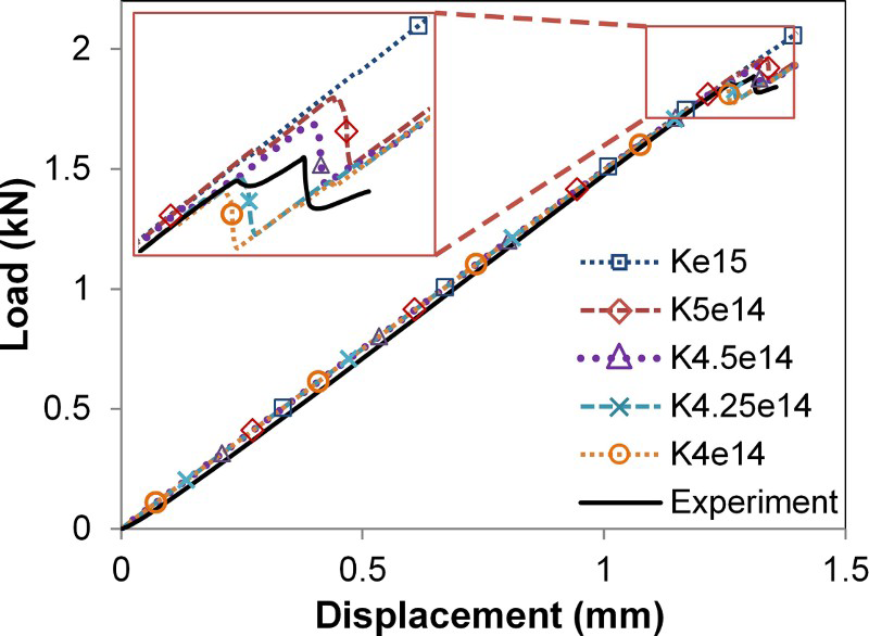
Effects of interfacial stiffness on results accuracy
Figure 8 shows that variation in interfacial strength did not affect the peak load significantly. For the sake of computational convergence, as already discussed, interfacial strengths of 40 and 70 MPa were selected for
 and
and
 , respectively. In this work,
 was assumed to be the same as
 .
.
Unlike the interfacial strength, the viscosity coefficient had a notable effect on the peak load (Fig. 9) and on computational convergence. When a viscosity coefficient was not applied, the simulation stopped before crack propagation. On the other hand, the use of a high value of the viscosity coefficient (μ = 10− 3) led to a lower computational cost, but the peak load was far above the experimental result. Taking account of the need for both accuracy and computational efficiency, a range of μ from 10− 5 to 10− 4 seems to be most appropriate for this particular simulation.
Finally, the interfacial stiffness has a remarkable influence on the simulation results (Fig. 10). It shows that the upper limit (1015 N m− 3) suggested by many investigators is not appropriate in this type of simulation because the peak load is far above the experimental value. A relatively low stiffness helps convergence but leads to inaccurate results. On the basis of the results in Fig. 10, an interfacial stiffness between 4.25 × 10¹⁴and 4.5 × 10¹⁴ N m− 3 should be selected.
Effects of number of stitch rows in crack region
As discussed previously, the TENF testing was carried out using an initial condition with only one stitch row in the crack region. Because of the limited specimen length, a test with more stitch rows in the crack region could not be conducted properly. The finite element analysis here investigates the effect of stitch rows in the crack region. The load–displacement curve (Fig. 11) reveals a significant effect of the number of stitch rows on the peak load. The more stitch rows there were in the crack region, the greater was the load needed to initiate propagation of delamination. However, an increasing load could not be considered as equivalent to an increasing energy release rate because the compliance of the laminates also changed owing to stitch bridging. To address this issue, further work is needed to understand the energy dissipated by the stitch during loading. The energy dissipation due to stitch penetration of the laminate, to plastic deformation of the stitch thread and to fracture should be quantified clearly. However, these aspects could not be considered in the present work.
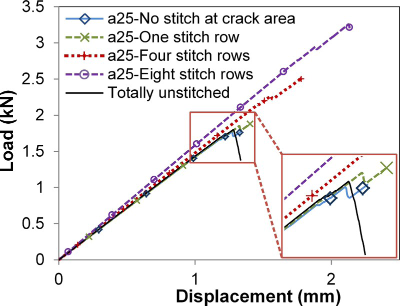
Effects of number of stitch rows at crack region on delamination behaviour
Furthermore, all of the stitched laminate models showed semistable crack propagation, even with no stitch row in the crack region. It should be noted that the absence of a stitch row in the crack region means that the model has stitch rows in the non-cracked region (and is not equivalent to a totally unstitched laminate model). The delamination behaviour is called semistable because propagation occurred when a step (a small drop in load) appeared in the load–displacement curve. Conversely, in the case of a totally unstitched laminate model, the load dropped drastically once delamination started to propagate. This showed that stitched laminates could suppress propagation of delamination.
Conclusions
A finite element model of the mode II delamination test has been successfully developed. A single stitched laminate was modelled under pure shear loading and the results verified by experimental data. Tabbed end notch flexural models were developed using a cohesive zone element to represent the crack propagation plane and adopting the techniques of single stitched laminate modelling. A study of the cohesive zone modelling parameters revealed that the interfacial stiffness K0 and viscosity coefficient μ have significant effects on accuracy and computational time, while the interfacial strength seems to have a negligible effect. The appropriate ranges for K0 and μ are 4.25 × 10¹⁴–4.5 × 10¹⁴ N m− 3 and 10− 5–10− 4 respectively. The finite element results also showed that the number of stitch rows in the crack region has a strong effect on the peak load before crack propagation. Finally, it can be concluded in general that the stitching technique can suppress propagation of delamination. Even though there is no stitch row in the crack region, the existing stitch threads ahead of the crack tip will immediately suppress the crack propagation once delamination starts to propagate.
Acknowledgements
The authors gratefully acknowledge the Tokyo Metropolitan Government for its financial support from the Asian Human Resources Fund and the Asian Network of Major Cities 21 (ANMC-21) Project. Special gratitude is extended to Dr B. Cox (Teledyne Scientific) for helpful discussion on the interlaminar shear test of single stitched laminates and to Dr H. Hoshi (Japan Aerospace Exploration Agency) for valuable input on this work.