
Abstract
High temperature behaviour of glass-vinyl ester stack liner at the operation temperature (20–121°C) was experimentally investigated by measurements on the small specimens and full scale specimens in this paper. Based on the stacking sequences of a typical glass-vinyl ester stack liner, three groups of small specimens were produced to evaluate the degradation of their tensile and compressive strength, the tensile modulus, and the flexural strength and modulus with increasing temperature, and one group of full scale specimens was prepared to measure their properties at room temperature. Furthermore, the ultimate axial tensile stress of a suspended glass-vinyl ester stack liner at various temperatures was derived according to the experimental results from the small specimens and full scale specimens. The high temperature behaviour of composites stack liner from the tests can be used as reference for determining the extreme operation temperature in coal-fired power plants.
Introduction
Many coal-fired power plants have not yet taken any effective measure to reduce the content of pollutants from the flue gas in China, which results in severe fog and haze in many cities over the past few years. Therefore, all the coal-fired power plants are required to instal the flue gas desulphurisation system to reduce the sulphur dioxide (SO2) content. Owing to strong liquid corrosion over the stack liner surface induced by the deposition and thermal shock of the flue gas after desulphurisation, the composites in many coal-fired power plants, as an alternative for traditional steel, are becoming an effective solution to improve the corrosion resistance and the temperature durability. However, composites generally have the low resistance at elevated temperature because of the low glass transition temperature of their resin. The temperature above the glass transition temperature can be induced at some operating or accident conditions, it is necessary to understand the high temperature behaviour of composites.
The changes in composites performance at different temperatures have been reported in terms of their tensile strength and modulus in previous study. The results indicate that composites present linear stress–strain relationship at room and elevated temperature, and the high temperature has significant effects on the fracture strength.1–3 The measurement on the compressive performance of GFRP laminate shows that the resin-dominated bending stiffness decreases more rapidly than the fibre-dominated compressive stiffness. 4 Furthermore, a large amount of published literature related to the high temperature performance of GFRP-reinforced concretes reveals that the decreases in load carrying capacity of concretes mainly depend on the reinforcement geometry, and presents the relationship between composites strength and temperature.5–11 The high temperature behaviour of the concrete element reinforced with CFRP has gained increasing attention recently.12–18
The high temperature behaviour of composites stack liner plays an important role in the design of the composites stack liner. However, limited data are available on composites manufactured with epoxy vinyl ester in coal-fired power plants. Most composites stack liner properties data used in design and analysis are obtained at room temperature, and a conservative value which represents the properties degradation value of the composites stack liner at operation temperature is adopted. It is imperative to investigate the strength and modulus degradation of the composites stack liner manufactured with epoxy vinyl ester at elevated temperature level to optimise the design of the composites stack liner, and to understand the required ultimate axial stress of the composites stack liner to balance the mechanical performance and corrosion performance of the layups of the composites stack liners. In this paper, a series of high temperature tests were performed in laboratory for small specimens and the room temperature tests were conducted for full scale specimens close to the power plant. Based on the results from the tests of small and full scale specimens, the properties degradation of the composites stack liner at various temperatures was derived. Furthermore, the ultimate axial tensile stress of a typical suspended composites stack liner manufactured with epoxy vinyl ester and ECR glass fibres was obtained at different temperatures according to the experimental results from the measurement on small specimens and full scale specimens.
Materials and Model
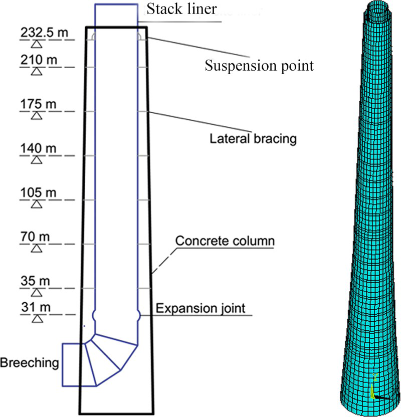
Composites are generally selected as anticorrosive materials in a chimney, which consists of the external concrete column with a gradually changeable diameter from bottom to top and the internal composites stack liner suspended in a platform. There are many platforms in the concrete column, including the lateral bracing interval and the support platform. The support platform is located at the top position close to 1/4 height of the stack. The suspended composites stack liners are typically 12–22 mm thick and the stiffeners should also be distant no < 8 m among each other. The use of stiffeners leads to reasonable composites stack liner thicknesses and reduces the requirement of the hoop strength. In fact, the changes and requirements in axial properties of the composites stack liner at various temperatures should be cared.
Figure 1 illustrates a schematic of the typical chimney consisting of a suspended composites stack liner and a concrete column with seven platforms. The composites stack liner contains an upper stack liner suspended in the top platform (232.5 m) and a lower stack liner in connection with the upper stack liner through an expansion joint at 31 m. The upper stack liner is 209 m long and 16.43 mm thick with a diameter of 8.5 m, and its structural layer is a 12.4 cross-ply laminate consisting of multiple plies of hoop-wound rovings and axially unidirectional fabrics. The lower stack liner is shorter and the requirement of its bearing capacity is thus lower than that of the upper stack liner. Table 1 gives the stacking sequences of the upper stack liner. Various loads are considered, such as the dead loads, wind loads, earthquake loads, pressure loads and thermal loads, including the normal-temperature load and the abnormal high temperature load in ASTM D5364. 19 The normal (50–80°C) and the abnormal (80–121°C) flue gas temperatures are considered here.
The illustration and theoretical model of a suspended composite stack liner
The stacking sequence of the composites stack liner
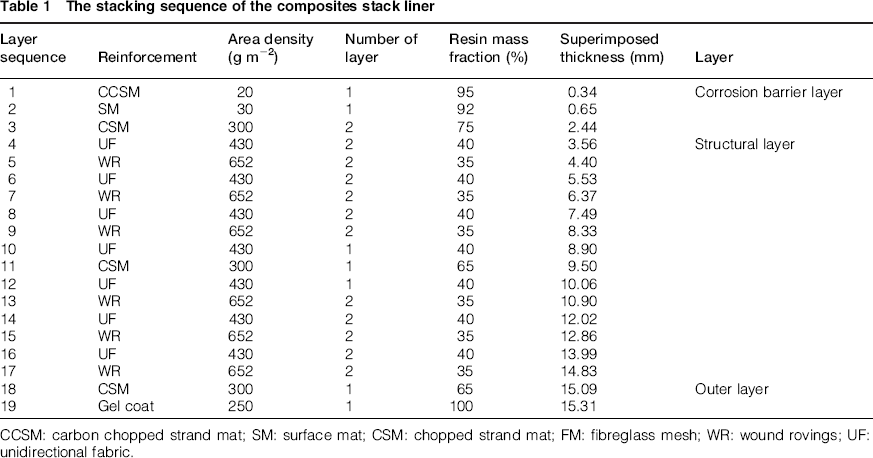
CCCM: carbon chopped strand mat; SM: surface mat; CSM: chopped strand mat; FM: fibreglass mesh; WR: wound rovings; UF: unidirectional fabric.
Experiments
Small test specimens
The experiments aimed at understanding the mechanical behaviour of the glass-vinyl ester stack liner exposed at elevated temperature. In the most power plants, the extreme temperatures are defined as 50, 63 or 80°C for normal operation temperature and 100 or 121°C for abnormal operation temperature. In order to accurately evaluate the composites stack liner performance at the high temperature, the specimens are tested at five temperature points (20, 50, 63, 80, 100 and 121°C). It should be noted that the composites stack liner is made of repeating alternating two unidirectional fabrics and two roving-wound layers in Table 1. However, it is difficult to directly evaluate the composites stack liner performance at evaluate temperature with full scale specimens because of the limited size of temperature regulating chamber. Thus, one group of small specimens (CP) is manufactured by less repeating cross-ply units up to the design thickness of small specimens (see Fig. 2). In order to present the reinforcement material effects on the high temperature behaviour of the composites stack liner, other two groups of specimens (UD (WR) and UD (UF)) reinforced, respectively, with wound rovings and unidirectional fabrics, are also produced. In this paper, considerable experimental efforts are paid for the characterisation of small specimens in terms of high temperature behaviour. The sizes of all small specimens are in agreement with the requirement in ASTM standards.20–22 Each group of specimens includes three types of small specimens, which are tensile, compressive and flexure specimens, respectively. Figure 2 shows the types of the specimens and their sizes.
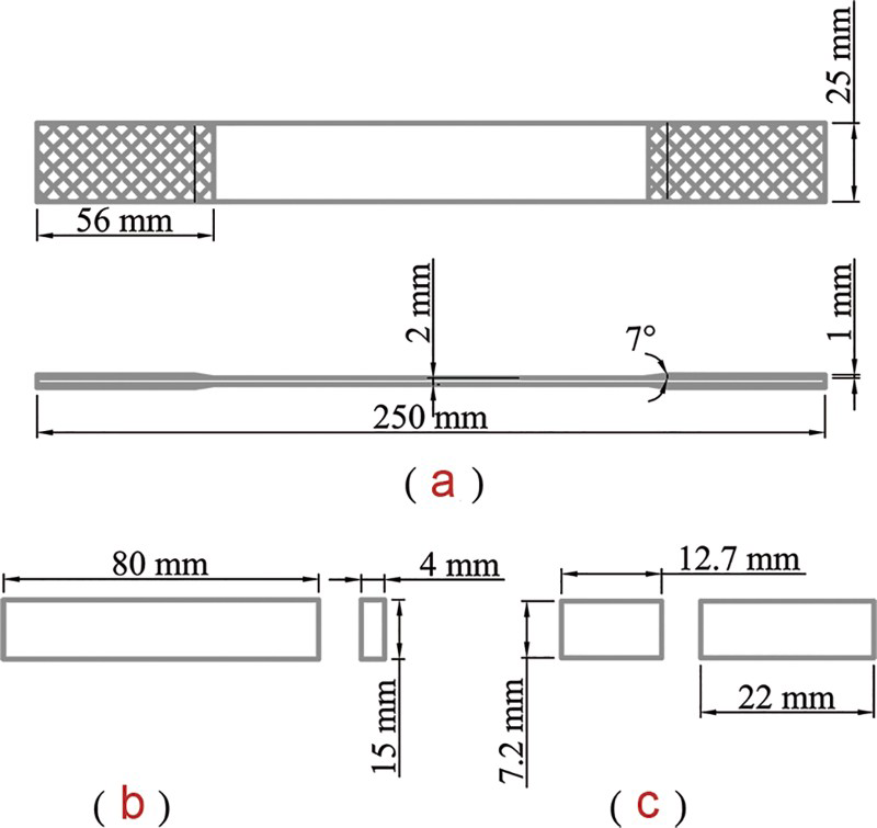
The types of small specimens: a tensile specimens, b flexural specimens and c compressive specimens at various temperatures
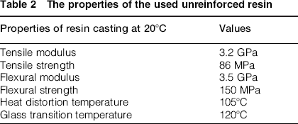
The used resin is Derakane 510c-350 from the Ashland with an improved temperature resistance and good corrosion resistance. Its performance is summarised in Table 2. Note that the tensile flexural strength is greater than tensile strength for resin casting because of the fact that the resin casting exhibits limited ductility in local region of high tensile stress under flexural state. The results can be supported by technical data sheets of various resin supplied by Ashland Inc. 23 The ECR glass fibres are in the form of rovings of more than 0.35 N tex 1 (2400 tex) yield (manufactured by CPIC industries) with typical performance attributes at the fibre level of 70 GPa, 1.5 GPa for tensile modulus and tensile strength, respectively. All small specimens are fabricated by filament winding process and the resin mass fraction of each ply should be the same as data presented in Table 1. For UD (WR) or UD (UF), 15 standard specimens (5 standard compressive specimens, tensile specimens and flexural specimens according to ASTM D695, ASTM D3039/D 3039M, and ASTM D790, respectively) are manufactured to measure the performance parallel to the fibre direction.20–22 For CP, 30 standard specimens are made to measure the performance in the axial direction (parallel to the fibre direction of the unidirectional fabrics) and the hoop direction (parallel to the fibre direction of wound rovings). The specimens of CP for measuring axial performance are referred to as CP (UF) and the others of CP are named as CP (WR) to obtain the hoop performance of specimens.
The properties of the used unreinforced resin
The specimens are measured at each target temperature after they are exposed for 2 h in the temperature regulating chamber at each target temperature. Figure 3a–c depicts the compression, tension and flexure test in the temperature regulating chamber, respectively. We can observe the failure process of specimens through the transparent observation port in the temperature regulating chamber. The tests are statistically insignificant because of their limited number; however, they provide a clear understanding of the high temperature behaviour of the composite stack liner under extreme conditions.
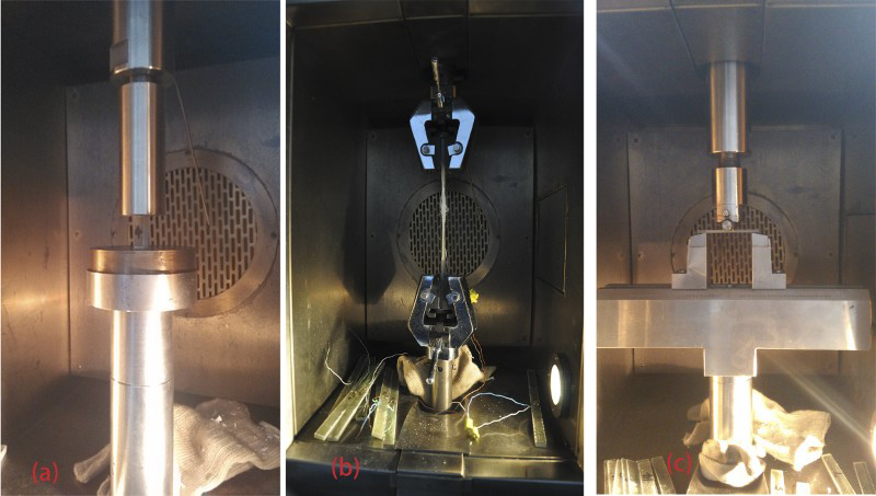
The tests in the temperature regulating chamber at various temperatures: a compression test, b tension test and c flexure test
Full scale specimens
The full scale specimens can truly describe the performance of the glass-vinyl ester stack liner. It is quite difficult to directly obtain high temperature behaviour of the composites stack liner by experimental measurement. However, we can measure the room temperature properties of full scale specimens and compare these properties with the properties of small specimens at room temperature to derive the relationship between the small specimens and full scale specimens. In order to adequately obtain the properties of the composites stack liner at room temperature, a full scale test section with 1 m long and 8.5 m diameter, is produced at the fabrication site according to the stacking sequences shown in Table 1. Figure 4 illustrates the test section fabricated by filament winding process on the mandrel. The resin mass fraction, assessed through the burn-off procedure, is approximately 35–40% for test section. The sizes of compressive, tensile and flexural specimens of the full scale specimens are in accord with the dimensions shown in Fig. 5. Note that the tensile specimens are fabricated based on the ASTM D638, which permits the specimens with thickness more than 7 mm to be measured. Prior to initiation of the test programme, the corrosion barrier and the outer surface layer should be excluded. The full scale specimens contain only the structural layer thickness (12.4 mm).
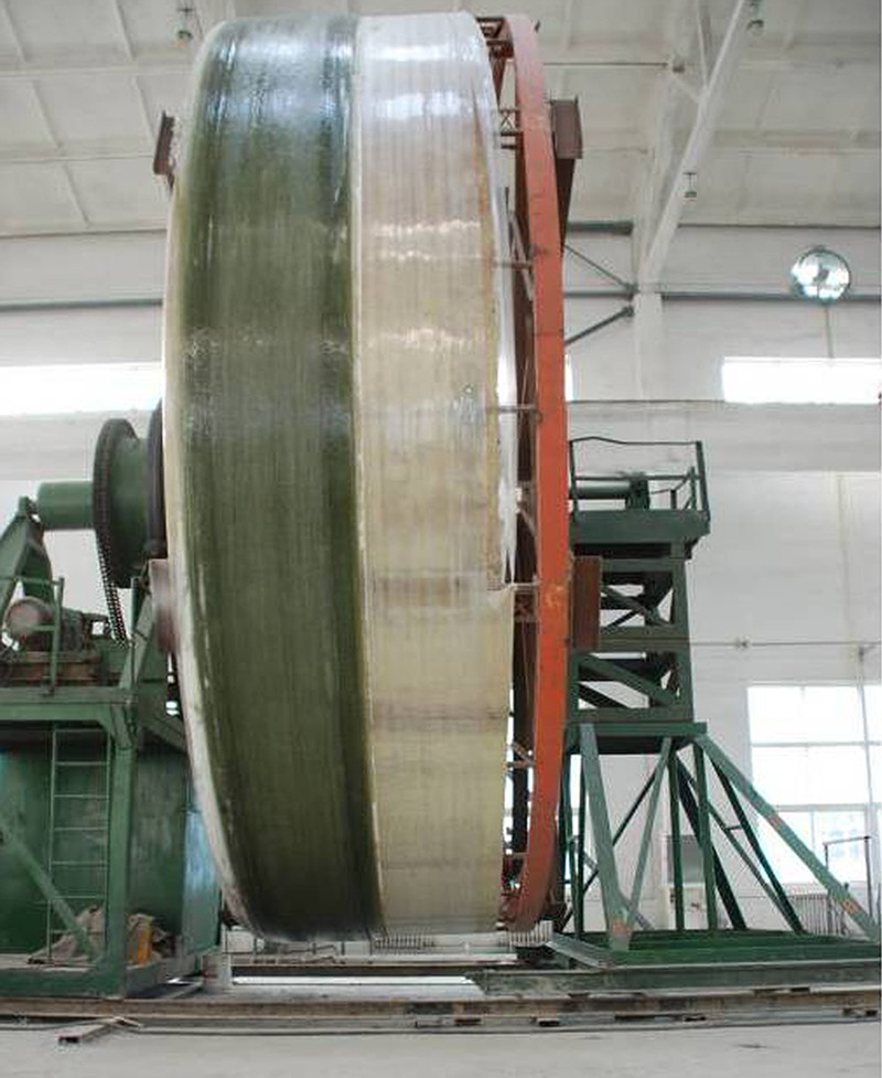
Test section on the mould
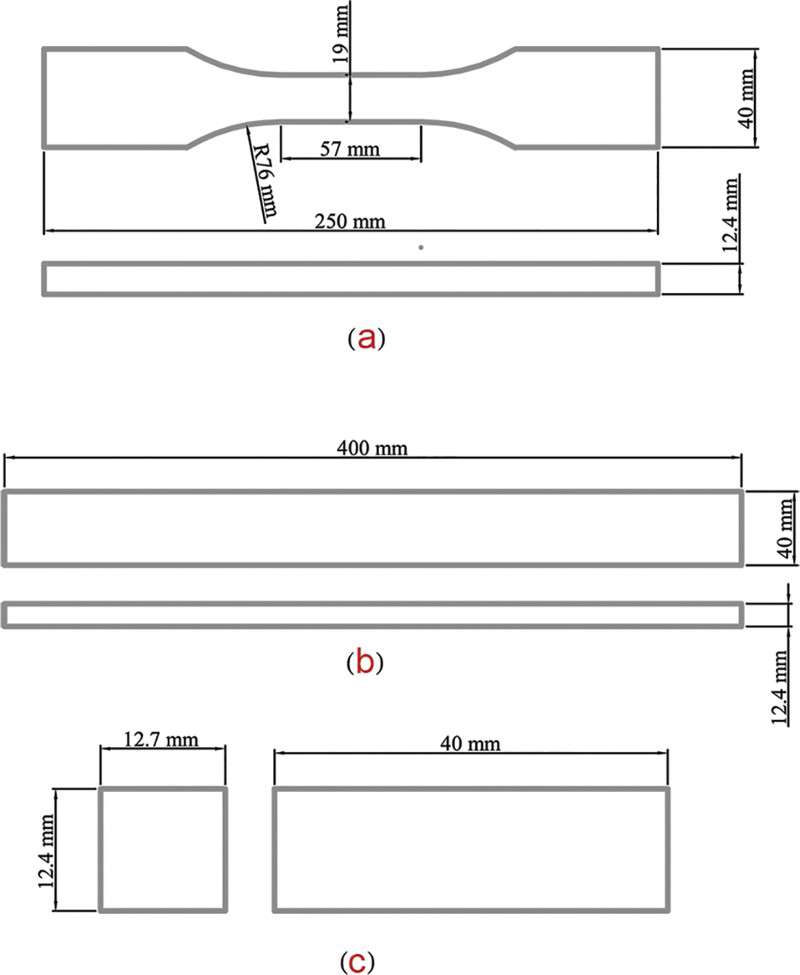
The schematics of full scale specimens: a tensile specimens, b flexural specimens and c compressive specimens
Results and discussion
Data recorded in all the tests are utilised to evaluate the strength and modulus of specimens reinforced with different reinforcements at various temperatures. At each target temperature, five tests are, respectively, conducted for each group of specimens in terms of compression, tension and flexure tests, and the average of five is taken as strength or modulus of specimens. Results from these tests are tabulated in Tables 3–8 (only the maximum and minimum values of five test values are listed).
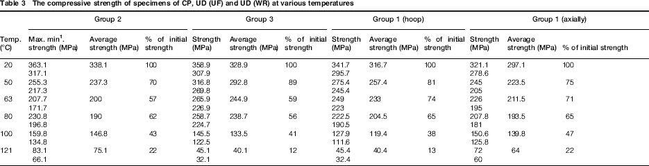
The compressive strength of specimens of CP, UD (UF) and UD (WR) at various temperatures
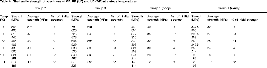
The tensile strength of specimens of CP, UD (UF) and UD (WR) at various temperatures
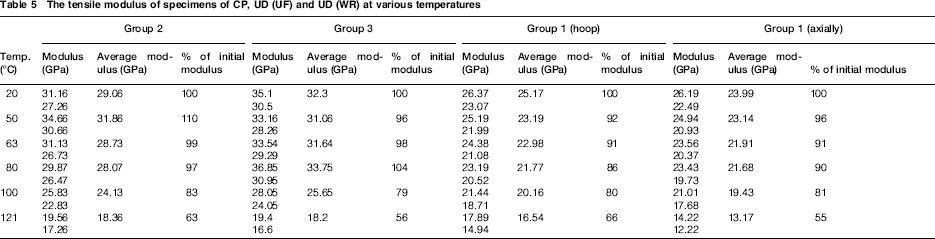
The tensile modulus of specimens of CP, UD (UF) and UD (WR) at various temperatures
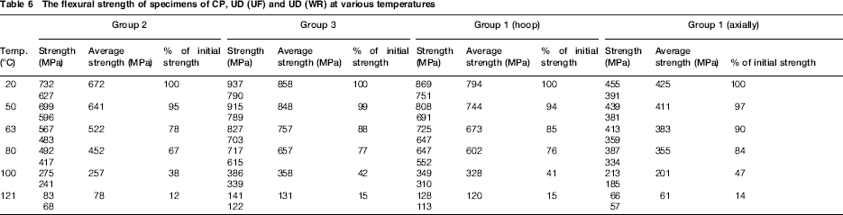
The flexural strength of specimens of CP, UD (UF) and UD (WR) at various temperatures
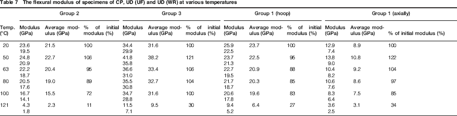
The flexural modulus of specimens of CP, UD (UF) and UD (WR) at various temperatures
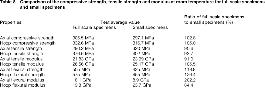
Comparison of the compressive strength, tensile strength and modulus at room temperature for full scale specimens and small specimens
The high temperature effects on the compressive strength
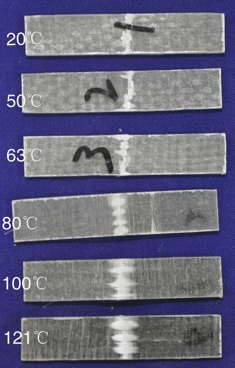
It can be found that the reduction of the compressive strength for all groups of specimens rapidly increases with the increasing temperature (see Table 3). All the compressive specimens lose at least 78% of their initial compressive strength at 121°C. The variation of average compressive strength for all groups of specimens is plotted in Fig. 6. The results show that the degradation of the compression strength for different groups of specimens follows the similar trend and appears to be proportional to temperature at 20–121°C. In addition, the failure modes of all compressive specimens at various temperatures are quite similar, wherein a sudden shattering occurs within the gauge section or close to the gauge length end of the end-tab and propagates into the gauge length. Figure 7 shows the failure modes of compressive specimens of CP (UF) at target temperature points. It should be noted that the compressive specimens are loaded in direct compression at specimen end and unsupported according to ASTM D695, as shown in Fig. 3a, thus multiple failure modes of compressive specimens, including the mixing of buckling failure and shattering, the mixing of shattering and longitudinal splitting. The actual compressive strength may be higher when other compressive test methods are performed.
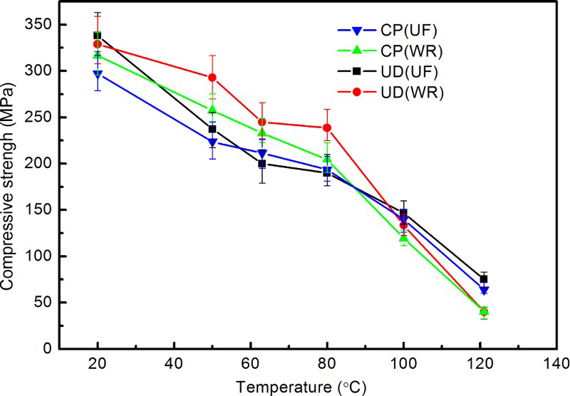
Variation in the compressive strength of specimens of CP, UD (UF) and UD (WR) with temperature
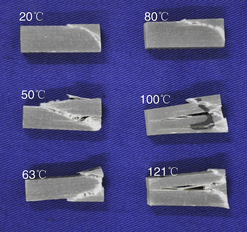
Compressive failure mode of specimens of CP (UF) at different temperatures
Considering that the temperature where the retained strength is 50% of the initial strength is treated as the critical temperature of specimens, referring to the data listed in Table 3 and following by linear interpolation, we obtain that the compressive strength of specimen of CP (UF), CP (WR), UD (UF), and UD (WR) drops to 50% of the room temperature strength at 97, 91, 90, and 94°C, respectively.
The high temperature effects on the tensile strength and modulus
Results from the tensile tests are tabulated in Tables 4–5. We can find that the reduction of the tensile strength and modulus for all groups of specimens still increases with the increasing temperature. Compared to the data in Table 3, the retained percentage of the initial tensile strength is higher than that of the initial compressive strength at all target temperature points. The degradation of the average tensile strength for all tensile specimens can be categorised into two stages (see Fig. 8a). At 20–80°C, the tensile strength gradually decreases at a slow pace, and the tensile specimens still retain at least 75% of the initial strength at 80°C. At 80–121°C, the tensile specimens experience a faster reduction in their strength, and the tensile specimens only retain no more than 38% of the initial strength at 121°C. Similarly, the degradation of the average tensile modulus follows the similar trend with the tensile strength for all tensile specimens (see Fig. 8b). At 20–80°C, the tensile modulus gradually decreases at a negligibly slow pace, even increases at some target temperature points for specimens of UD (UF) and UD (WR). At 80–121°C, the tensile specimens exhibits a faster reduction in their modulus with increasing temperature, especially at the temperature beyond heat distortion temperature of resin (close to 100°C). However, the degradation of the tensile strength loses more rapidly than that of the tensile modulus for each group of specimens at all target temperature points as shown in Fig. 8a, b. In addition, the failure modes of tensile specimens at 20–121°C are also quite similar and the failures are mainly in the central region, wherein the specimens split into bunch of fibres as cracks. These fibres are gradually stretched or pull out and the tensile specimens lose their integrity and strength eventually. Figure 9 shows failure modes of tensile specimens of CP (UF).
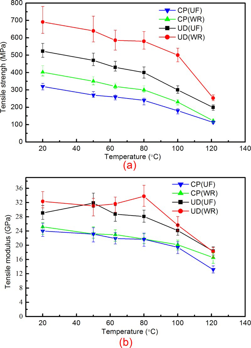
Variation in the tensile properties of specimens of CP, UD (UF) and UD (WR) with temperatures: a tensile strength, b tensile modulus
Tensile failure mode of specimens of CP (UF) at different temperatures
The results presented here indicate that the high temperature has greater effects on the compressive strength than on the tensile strength. The composites stack liner is thus suitable to be suspended as the result of the lower values and the faster degradation of the compressive strength at high temperature. Similarly, considering that the temperature where the retained strength is 50% of the initial strength is treated as the critical temperature of specimens, referring to the results obtained from Table 4 and following by linear interpolation, we obtain that the tensile strength of specimen of CP (UF), CP (WR), UD (UF), and UD (WR) drops to 50% of room temperature strength at 106, 106, 108, and 113°C, respectively.
The high temperature effects on the flexural strength and modulus
The drops in the flexural strength and the modulus at six temperature points are tabulated in Tables 6–7 for all groups of specimens, respectively. We can find that the reduction of the flexural strength and the modulus for all groups of specimens still increases with the increasing temperature. The degradation of the average flexural strength follows similar trend with the tensile strength (see Fig. 10a). However, a relatively lower percentage of the flexural strength is retained as compared to the tensile strength beyond 80°C. The decrease in the flexural modulus follows different trends with the average tensile modulus, as shown in Fig. 10b. Beyond 100°C, the decrease in the flexural modulus is at a faster pace and all flexural specimens lose at least 70% of the initial modulus at 121°C. A wide range of failure modes, with the tensile fracture of the outer surface to be accompanied by the break of fibres, the tensile fracture of the outer surface and the compressive fracture of outer surface, occur under three point flexure tests at various temperatures. However, the dominated failure types to be observed in the tests are the compressive fracture of the outer surface at 20–121°C for the flexural specimens. This is mainly attributed to the lower compressive strength than the tensile strength, resulting in that the stress in the outer face for flexural specimens first reaches the compressive facture strength during bending tests. The conclusion is in good agreement with the experimental result that the tensile strength is higher than the compressive strength from the data shown in Tables 3–4. Figure 11 shows the primary failure modes of flexural specimens of CP (UF). Similarly, the flexural strength of specimens of CP (UF), CP (WR), UD (UF), and UD (WR) drops to 50% of the room temperature strength at 98, 93, 91, and 93°C, respectively.
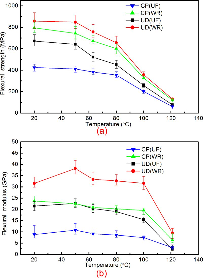
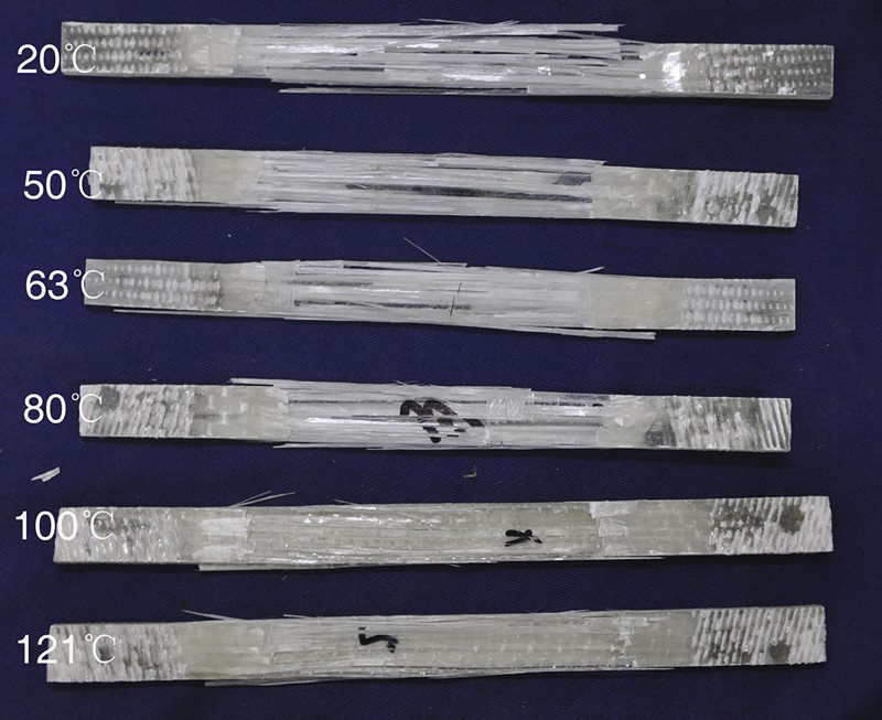
Variation in the flexural properties of specimens of CP, UD (UF) and UD (WR) with temperatures: a flexural strength, b flexural modulus
The flexural failure mode of specimens of CP (UF) at different temperatures
The results of full specimens
Figure 12 gives the strength and modulus of the full scale specimens cut from the test section at room temperature. The results reveal that the tensile strength and compressive strength are significantly less than the flexural strength in the axial and hoop direction at room temperature. The results are in good agreement with the conclusion obtained from the small specimen. Table 8 presents the difference in the compressive strength, tensile strength and modulus of full scale specimens and small specimens of CP at room temperature. The experimental results for the full scale specimens and the small specimens are very close, with a maximum difference of 9.4%, except for the flexural results. The performance of small specimens can accurately represent the compressive strength, tensile strength and modulus of the composites stack liner. Furthermore, a large difference in flexural properties of full specimens and small specimens occurs because of high dependence of flexural properties on the function of ply stacking sequences. Thus, the performance of the small specimens cannot reflect the actual properties of the composites stack liner.
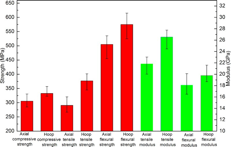
The axial, tensile and flexural properties of the glass-vinyl ester stack liner in the axial direction and hoop direction
As mentioned in Small test specimens section, it is quite difficult to directly measure the properties of full scale specimens of the composites stack liner at elevated temperature because of the limited size of temperature regulating chamber. However, it has been demonstrated that the performance of small specimens can accurately represent the compressive strength, tensile strength and modulus of the composites stack liner. Thus, the performance of the composites stack liner at elevated temperature can be derived based on the properties degradation trend of the small size specimens and the properties of full scale specimens at room temperature, for instance, the tensile strength of the composites stack liner at 121°C can be considered as 101.6 (290.2 × 35% = 101.6) MPa. For the suspended composites stack liner in Fig. 1, its axial tensile strength is mainly concerned. Considering that the temperature where the retained strength is 50% of the initial strength is treated as the critical temperature of the composites stack liner, 97 and 106°C thus can be regarded as the conservative critical axial compressive and tensile strength temperature of the composites stack liner based on the conclusions in The high temperature effects on the compressive strength and The high temperature effects on the tensile strength and modulus sections.
The ultimate axial tensile stress for the suspended composites stack liner
The composites stack liner in Fig. 1 is mainly subjected to the axial membrane stress and the shear stress can be insignificant under various loads. Thus, ultimate axial tensile stress for the suspended composites stack liner with stacking sequences shown in Table 1 is investigated here. It can be seen that the average tensile strength of the composites stack liner in the axial direction is 290.2 MPa in Table 8. Referring to the degradation trend of the tensile strength of CP (UF) in Table 4, the axial tensile strength for the suspended stack liner can be derived as 145.1 Mpa (145.1 = 290.2 × 0.5) and 101.5 Mpa (101.5 = 290.2 × 0.35) at the critical temperature of tensile strength (106°C) and the maximally abnormal temperature, respectively. Assuming 10 as a conservative design safety factor stipulated by the ASTM D 5364 and ASME RTP-1, the ultimate axial tensile stress for composites stack liner under various loads should be 14.51 and 10.15 MPa below the critical temperature of tensile strength (106°C) and the maximally abnormal temperature, respectively.
Conclusions
The main goal of this study is to provide the high temperature behaviour of the glass-vinyl ester stack liners for coal-fired power plants, and to understand the ultimate axial tensile stress of a typically suspended composites stack liner under various loads. In conclusion, we can state the following:
At the operation temperature 20–121°C for coal-fired power plants, the compressive strength of the glass-vinyl ester stack liner decreases at a faster pace than tensile strength, and nearly presents a linear degradation with increasing temperature. The reduction in the tensile modulus follows similar trend with the tensile strength for the glass-vinyl ester stack liner, and the degradation ratio of tensile strength is bigger than that of the tension modulus. Below the normal operation temperature (80°C), the glass-vinyl ester stack liner retains most of the tensile strength and modules, while it rapidly loses the tensile strength and modules beyond 80°C. The primary failure mode of the flexural specimens is the compressive fracture of the outer surface as a result of the fact that the compressive strength is lower than the tensile strength. Considering that the temperature where the retained strength is 50% of the initial strength is treated as the critical temperature of the glass-vinyl ester stack liner, 97 and 106°C are considered as the critical temperature for axial compressive strength and tensile strength of the glass-vinyl ester stack liner, respectively. The ultimate axial tensile stress for the suspended glass-vinyl ester stack liner using the stacking sequences in Table 1 under various loads is 14.51 and 10.15 MPa below the critical temperatures of tensile strength (106°C) and the maximally abnormal temperature, respectively.
Footnotes
Acknowledgements
This work is supported by the National Natural Science Foundation of China (Grant No. 11302168) and the Natural Science Foundation of Hubei Province (Grant No. 2014CFB140).