
Abstract
This study aims at understanding the physicochemical phenomena which take place during pressureless cosintering of Hadfield steel (X120Mn12) and cemented carbide (WC cemented by an Fe rich binder). The experimental approach consists in studying the sintering behaviour of single materials (dimensional changes and weight losses during sintering, microstructure and hardness after sintering) before studying cosintering. Two bimaterial architectures are investigated: one consists of a two layer bimaterial and the other consists of cemented carbide inclusions in steel matrix. For both architectures, when the contact between materials is achieved, a multiphase intermediate layer appears between the two materials. This intermediate layer consists of a M6C continuous matrix with remaining WC grains at the cemented carbide side and with Fe rich islands at the steel side. M6C formation is the result of WC dissolution and asymmetric diffusion of W and C in the steel layer.
Keywords
Introduction
The manufacture of multilayered materials by powder metallurgy has numerous advantages. The production cycle is reduced to two major steps: co-compaction or co-powder injection moulding, and cosintering. The post-sintering machining is minimised as near net shapes are achieved. The powder metallurgy technique has been applied to a wide range of material combinations: metal–metal [e.g. M2/17-4PH,1 316L/17-4PH,2 316L/M2,3 and Ti/Al3Ti (Ref. 4)], ceramic–ceramic [e.g. PZT/PZT,5 Al2O3/Ti3SiC2,6 and Al2O3/ZrO2 (Ref. 7)] and metal–ceramic [e.g. W/Al2O3,8 Ti/TiB2/B,9 NiCr/ZrO2,10 430L/3Y-TZP,11 and 316L/WC–Co.12
This study aims at understanding the physicochemical phenomena which take place during cosintering of a steel/cemented carbide bilayered component. Such materials combining tough and hard properties can be applied in industrial and domestic sectors where the common needs are the impact and wear resistances (drilling and cutting tools, rolls for cold rolling mills, armour plate, etc.).
The authors’ experimental approach first consists in studying a model bimaterial. In previous papers,13,14 a model bimaterial, steel (Fe–WC–C)/cemented carbide (WC–Fe–C), has been investigated and a three step methodology has been defined to study the bimaterial:
materials selection, on the basis of thermodynamic considerations and cosintering criteria
study of single materials sintering, in order to define the range of a priori suitable sintering conditions
study of bimaterials cosintering, with emphasis on interface phenomena.
For the model bimaterial, coupled formation of M6C carbides and liquid in the interfacial area during sintering was evidenced and understood.13
In this paper, Hadfield steel, X120Mn12, is used instead of the Fe–WC–C steel (steel of the model bimaterial) to get higher the mechanical properties of steel part. The aim of this study is then to achieve the direct processing of a Hadfield steel/cemented carbide bilayered component by powder metallurgy.
The three step methodology is applied for this new bimaterial. The knowledge of the liquid and M6C formation mechanisms are used to understand the results obtained with the Hadfield steel.
Experimental procedure
The Hadfield austenitic manganese steel, X120Mn12, is characterised by a high work hardening capacity upon impact and good abrasion resistance in comparison with Fe–WC–C steel of the model bimaterial. The water atomised prealloyed powder (provided by Höganäs) used in these investigations has the metallic composition but no carbon. This carbideless powder was expected to be softer and more compressible. Carbon (1·2 wt-%) was added as graphite powder (UF4, Höganäs) to achieve the full nominal composition of X120Mn12 (Table 1). The irregular shape of powder produced by water atomisation was expected to facilitate powder grains interlocking during compaction (Fig. 1). An organic lubricant (0·8 wt-% Kenolube) was mixed with powders in a biconic mixer to improve green strength and compressibility.15
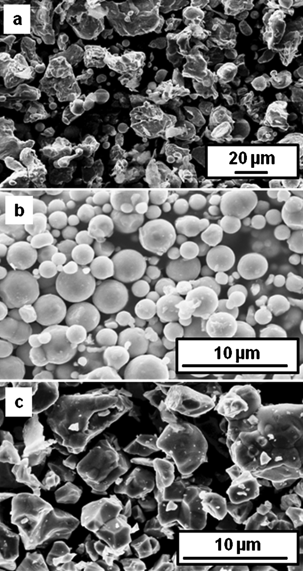
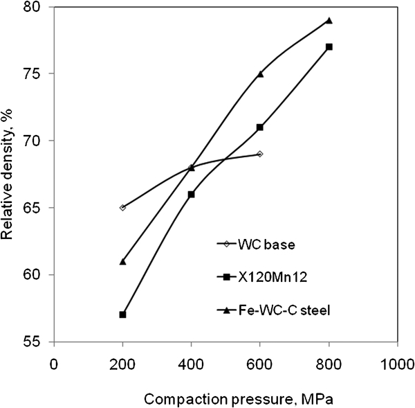
Images (SEM) of a water atomised prealloyed X120Mn12+graphite (d50 = 56 μm), b Fe (d50 = 6·8 μm) and c WC (d50 = 6·1 μm) powders
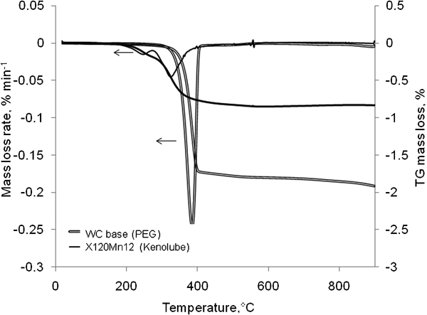
Nominal composition and laser granulometry d50 of X120Mn12 steel and graphite powders
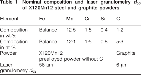
The cemented carbide powder mixture, named WC base mixture, was prepared from Fe, WC and graphite (Cg) powders (Fig. 1) according to the attrition procedure previously described.14 Attrition was carried out to achieve homogeneous powder mixture of WC–6·6Fe–0·14C (wt-%) and to add organic binder, 2 wt-% polyethylene glycol (flakes of PEG 3400). The composition of the powder mixture, particularly the carbon content, is adjusted to enable the liquid phase sintering of the WC base material and prevent M6C formation.16 Indeed, the WC+L domain of the Fe–W–C isopleth section for the sintering temperature window is very narrow and a depletion of carbon in the mixture produces M6C in the final material.
The uniaxial compaction (single action mode) was used to produce cylindrical 8 mm diameter compacts. To determine the suitable co-compaction pressure, the relative green density, determined from the ratio between experimental density and theoretical density, was estimated for compaction pressure values up to 800 MPa (800 MPa is a technical limit value). Experimental green densities were determined from weight and size measurements. The theoretical density of WC base materials (14·6 g cm−3) was calculated from the initial constitutive material densities and the bulk steel density was used for X120Mn12 (7·88 g cm−3).
The debinding and sintering steps of compacts were first investigated for each single material. The PEG and Kenolube removal characteristics were achieved by thermogravimetric analysis (TGA; Setaram Setsys 16/18) up to 900°C in He – 4 mol.-%H2 flow with a heating rate of 5 K min−1. After debinding, the samples were heated at 5 K min−1 in argon atmosphere up to the sintering temperature. The linear dimensional changes during sintering were measured by vertical dilatometry (Setaram TMA92·16/18).
The density of sintered samples was determined by the Archimedes method. Microstructures were examined on cross-sections by SEM (LEO Stereoscan 440) and phase identification was performed using X-ray diffractometry (PANalytical X'Pert PRO MPD). Mechanical properties were estimated through Vickers hardness measurements (Wolpert DIA Testor N2).
Single materials: Hadfield steel and cemented carbide
Compaction and debinding
The effect of compaction pressure on green density, as shown in Fig. 2, is higher for steels (Fe–WC–C steel of the model bimaterial or X120Mn12) than for WC base material because of the poor compressibility of the hard WC particles. The compressibility of X120Mn12 is lower than that of the Fe–WC–C steel but its curve exhibits the same trend. Therefore, the compaction pressure chosen for the model bimaterial,14 600 MPa, is also suitable for this bimaterial. After compaction at 600 MPa, the average values of green densities are 10·0 g cm−3 (69%) for WC base compact and 5·6 g cm−3 (71%) for X120Mn12 compact. Such close values are favourable to cosintering because they are expected to prevent differential shrinkage stresses. Indeed, close green densities are expected to result in close shrinkages during sintering if complete densification is achieved. Numerical simulation was then used by Thomazic et al. to optimise pressing conditions of the model bimaterial in order to ensure a homogenous distribution of relative density in each layer.17 These simulation results can be extended to the present bimaterial since the compaction behaviour of model steel and X120Mn12 are similar. They showed that density gradients depend on the order of die filling, i.e. whether the WC base layer is below or above the steel layer. When the WC base material is above the steel one, the density is more homogeneous and better results are expected for sintering. The resulting mean density is between the experimental values of the two single materials.17
Evolution of relative green density of WC base, X120Mn12 and Fe–WC–C steel compacts versus compaction pressure
For WC base compact containing 2 wt-%PEG, TGA measurements shows that the rapid removal occurs in one step between 300 and 405°C (Fig. 3). The main decomposition products are CO2, CO and small fragments of hydrocarbon.18
Mass loss and mass loss rate of WC base (organic lubricant: 2 wt-%PEG) and X120Mn12 (organic lubricant: 0·8 wt-% Kenolube) compacts during TGA experiments (He–4 mol.-%H2, 5 K min−1 up to 900°C)
For X120Mn12 compact containing 0·8 wt-% Kenolube, the organic lubricant is removed in two steps between 145 and 580°C as in investigations by Bergkvist and Andersson15 on 409Nb steel. The starting temperature is above the melting point of Kenolube (100–140°C).19 As Kenolube contains 20 wt-% zinc stearate and 80 wt-% N,N′-ethylenebisstearamide (EBS),19 the two step weight loss observed in Fig. 3 can be related to the two components. The first mass loss (0·17%) from 145 to 265°C corresponds to 20% of the total mass loss and the second one (0·68%) from 265 to 580°C corresponds to 80% of the total mass loss (0·85%). Therefore, the first mass loss could correspond to the zinc stearate removal and the second one to the EBS removal. Ward20 has investigated the zinc stearate removal and Baum et al. 21 the EBS removal in iron compacts. Ward has indicated that the decomposition products of zinc stearate up to 500°C were alkane long chains (CnH2n+2 with n = 16 or 17).20 During EBS removal, Baum et al. have shown that large molecule products were emitted in significant amounts with CO2, CO, CH4 and C2H4 in lower amounts.21 Above 580°C, as for zinc stearate, only residues of zinc oxide are still present in samples lubricated with Kenolube.19
During Kenolube removal, decomposition products condense in the cool part of the furnace, particularly in the gas outlet, resulting in contamination and sometimes obstruction. Consequently, the sintering process is performed in two steps: debinding is carried out in tube furnace equipped with a condenser, and then cooled samples are transferred to the dilatometer to be sintered.
For both compacts, the ranges of debinding temperature are different due to different organic binders: 300–405°C for the WC base compact and 145–580°C for X120Mn12 compact. Moreover for X120Mn12 compact, the mass loss rate is five times lower than for WC base compact. Consequently, the higher debinding temperature must be selected to perform the isothermal co-debinding stage of the bimaterial compact. A debinding temperature of 550°C is sufficient because more than 99 wt-% of kenolube are already removed (Fig. 3) and this temperature is held during 60 min. After co-debinding and cooling to room temperature, cohesion between the two layers is bad and lead to crack formation or sample break. A presintering stage is therefore added to the thermal cycle. The 60 min co-debinding stage at 550°C is followed by a presintering 10 min plateau at 1000°C.
Sintering of single materials
In the previous article,13 the sintering temperature range for WC base sample, 1280–1300°C, was defined from thermodynamic equilibria in Fe–W–C system (calculated with Thermo-Calc software22 using the TCFE5 database).23
For X120Mn12, the calculated isopleth section for 12·5Mn–1·5Cr–0·4Si (wt-%) is presented in Fig. 4a. The authors’ results are compared with a recent assessment on the Fe–Mn–C ternary system.24 The vertical line corresponds to the carbon content in X120Mn12. The calculated evolution of the γ and liquid volume fractions with temperature is presented in Fig. 4b. From these curves, the temperature of the first liquid formation is 1208°C and liquidus temperature is 1390°C. In order to prevent material collapse during supersolidus sintering of X120Mn12 at a temperature above 1208°C, it is necessary to keep the volume fraction below typically 35%, and therefore temperature below 1300°C.
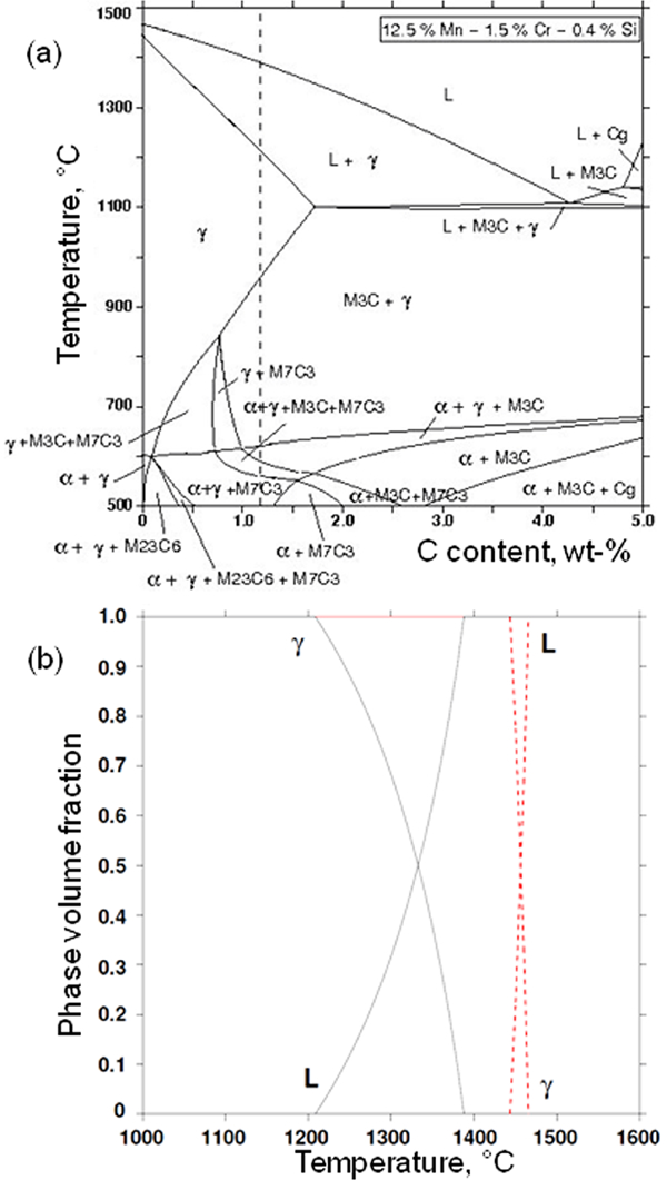
a calculated isopleth section for 12·5Mn–1·5Cr–0·4Si (wt-%, dotted line indicates composition of X120Mn12) and b calculated evolution of volume fractions of γ and liquid versus temperature (dotted curves are plotted from composition of X120Mn12 without C)
This interval of sintering temperatures, defined from X120Mn12 criteria, is compatible with the WC base one. The maximum sintering temperature, 1300°C, was first chosen to promote densification of both materials.
The height changes (ΔH/H) of the single material compact during sintering is measured in a vertical dilatometer. The thermal treatment of WC base compact is performed in two stages in the dilatometer: a debinding stage (1 h at 360°C in He–4H2 flow) followed by a sintering stage. As explained above, the X120Mn12 samples are first debound in a specific furnace to remove Kenolube before the sintering stage carried out in the dilatometer.
Figure 5 shows dilatometric curves for WC base and X120Mn12 compacts (H = D = 8 mm) heated under argon flow at 5 K min−1 and isothermally held at 1300°C during 60 min. The main features of the WC base material behaviour during sintering, described in detail in a previous article,14 are reported in Table 2.
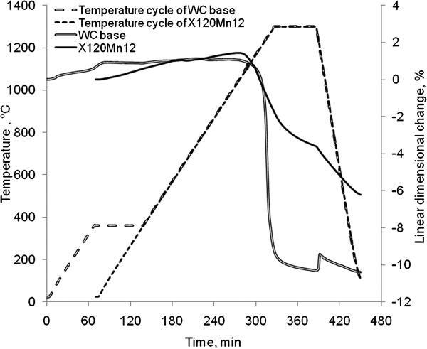
Dilatometric curves and thermal cycle for WC base and X120Mn12 compacts (H = D = 8 mm) heated under argon flow at 5 K min−1 and isothermally held at 1300°C during 60 min
Cosintering criteria from single materials behaviour and Vickers hardness
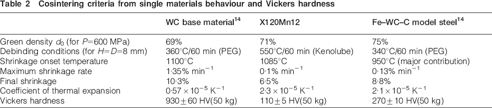
For X120Mn12, up to 600°C, only thermal expansion is observed. From 600°C, the α phase shrinkage begins. From 700 to 1085°C, after the α–γ transition, shrinkage is stopped in γ phase. From 1085°C, corresponding to the transition from expansion to shrinkage, shrinkage restarts and continues during the isothermal stage. At the end of the plateau, the shrinkage rate is still nonzero, so that a longer dwell time is expected to enable higher densification. During cooling down to room temperature, the additional decrease in ΔH/H is mainly due to thermal shrinkage. The slope is about 2·3×10−5 K−1 which is consistent with the typical thermal expansion coefficient of austenitic steel. The final shrinkage measured at room temperature is isotropic and ∼6·5%. The density is 6·65 g cm−3. The main features of the X120Mn12 behaviour during sintering are also reported in Table 2.
The hardness of WC base is acceptable regarding the required mechanical properties. Hardness value of X120Mn12 is too low but X120Mn12 needs to be annealed, quenched and tempered after sintering to obtain its specific properties.
The other features reported in Table 2 are examined to estimate the ability of X120Mn12 to be cosintered with WC base material in comparison with the Fe–WC–C steel of the model bimaterial. Like for Fe–WC–C steel, the shrinkage rate of X120Mn12 is ∼10 times lower than the WC base material one. Moreover, the thermal expansion coefficient, determined from dilatometric curve on cooling, is four times higher than the WC base one. The small difference of shrinkage onset temperature between WC base material and X120Mn12, lower than the difference observed between WC base material and Fe–WC–C model steel, is a priori favourable to cosintering. Nevertheless, the mismatch between the final shrinkages of WC base material and steel is higher when WC base material is combined with X120Mn12 than with the model steel. This shrinkage mismatch may cause distortions in the interfacial area and possibly the formation of cracks at the interface between the two materials. A sintering experiment with reducing atmosphere (He–4H2 flow) has been achieved to improve the densification of X120Mn12. But, no increase in shrinkage was observed and a mass loss of ∼3·2% was observed like in experiments under argon flow. A TGA/differential thermal analysis (DTA) experiment was performed to identify the origin of these mass losses. X120Mn12 powder was heated up to 1565°C at 5 K min−1 under He–4H2. After 30 min at 1565°C, the sample was cooled down at 5 K min−1. The TGA curve exhibits two successive mass losses (Fig. 6). The first one occurs between 1000 and 1300°C and reaches ∼2·5%. This loss is probably due to carbon loss (major contribution), reduction of internal and surface oxides, reduction of zinc oxide and zinc volatilisation (organic lubricant residues). Above 1300°C, the second mass loss takes place (about −7·5%) and could be due to Mn volatilisation. At all temperatures, the vapour pressure of Mn (e.g. 19·15 Pa at 1100°C) is significantly higher than that of Fe and Cr (e.g. 8·8×10−8 and 3·25×10−3 Pa at 1100°C respectively).25 Moreover, vapour pressure of Mn, which is 0·4 Pa at 900°C, increases sharply at higher temperatures (e.g. 3·28 Pa at 1000°C, 19·15 Pa at 1100°C and 318 Pa at 1300°C).25 For sintering experiments, 1300°C appears to be the maximum temperature, but needs carbon losses to be accurately controlled or balanced.
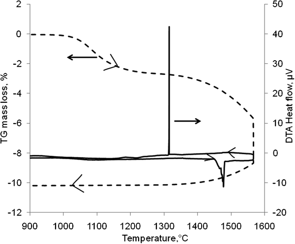
Analysis of X120Mn12 powder using TGA/DTA (vheating = vcooling = 5 K min−1, 30 min at 1565°C, He–4H2)
The nature of the X120Mn12 powder used in these investigations promotes carbon losses, because oxides such as Fe, Cr and Mn oxides are formed during powder processing by water atomisation. These oxides have been reduced by the graphite added after atomisation. Carbon loss is confirmed by DTA curve (Fig. 6) which reveals that the liquid appears around 1450°C instead of 1208°C. This higher value, 1450°C, is related to the temperature of the first liquid formation for the X120Mn12 composition without carbon, i.e. Fe–12·5Mn (dotted curves in Fig. 4b). According to the calculated isopleths in Fig. 4a, M7C3 and M3C carbides are expected to be present in the final microstructure. These carbides are not detected by XRD and SEM. X-ray diffraction only evidenced the bcc α phase, the fcc γ phase and the metastable hcp ϵ phase which were also detected in the starting powder.
Two layer component: X120Mn12/WC base material
To limit carbon losses above 1000°C, the two layer compacts were sintered in a graphite resistor furnace using the atmosphere (dry argon flow then static atmosphere) defined to control the C potential. As explained above, the sintering temperature must be <1300°C to prevent large Mn volatilisation. The two layer compacts were heated at 5 K min−1 up to 1290°C. After 60 min at 1290°C, the samples were rapidly cooled. After sintering, the mass loss of X120Mn12, ∼2%, is lower than the value obtained for the monomaterial (3·2%) previously sintered at 1300°C during 60 min in Ar flow.
After cooling to room temperature, the total axial shrinkage is 6·4%. The radial shrinkage difference between layers (steel radial shrinkage–WC radial shrinkage = 1·2%) induces a small plastic deformation of the ductile layer (steel) and cracks formation in the WC base layer (Fig. 7). The crack starts from the external surface of the sample, close to the interface between layers, and propagates inwards, with a small angle with respect to the interface between layers. In Simchi and Petzoldt investigations on 316L/WC–Co cosintering, a detachment of the contact area is observed.12 Indeed, the mismatch strain is higher for 316L/WC–Co bimaterial since the difference of onset shrinkage temperature is higher (respectively 1192 and 1253°C).12
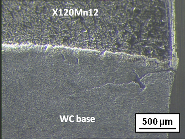
Cracks in WC base layer of X120Mn12/WC base bimaterial
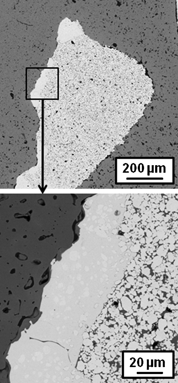
Observation of cross-sections by SEM revealed that an intermediate layer, ∼90 μm thick, was formed between the two layers (Fig. 8). The cracks observed in the intermediate layer show that the differential shrinkage stresses are significant (Fig. 8b). These cracks seem to be initiated at the interface with steel and propagate perpendicularly to the interface through the intermediate layer until reaching the WC base layer. Observations by SEM coupled with EDX analysis reveal that the intermediate layer is not homogeneous and mainly consists of an Fe,W rich phase with small amounts of Mn and Cr (grey in Fig. 8b). The Fe/W ratio (from 1·07 to 1·14) is consistent with Fe3W3C (i.e. M6C). X-ray diffraction pattern confirmed this conclusion (Fig. 9): the same phases as the monomaterials are observed, i.e. hcp WC carbide and bcc Fe rich binder of WC base material (α phase) and bcc and fcc Fe rich phases in X120Mn12 monomaterial (α and γ phases), but with an additional phase Fe3W3C. A similar intermediate layer formation has been already mentioned during the cosintering of 316L/WC–Co bimaterial.12 The small rounded objects close to the WC base material are remaining WC particles (in light grey in Fig. 8b). The dark phase is the Fe rich binder in which Mn, Cr and W are detected.
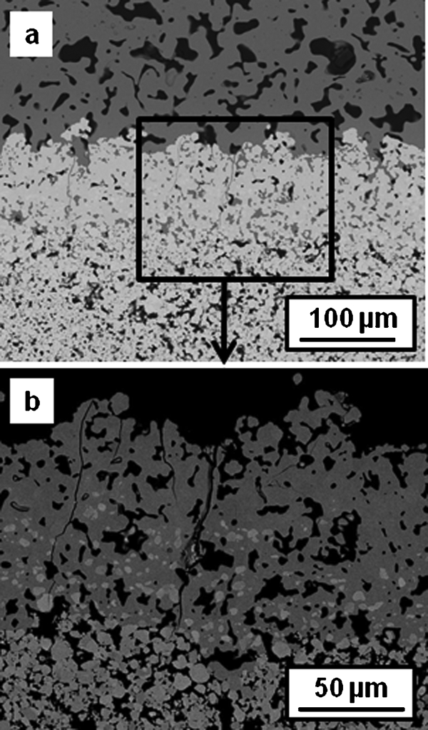
Images (SEM) of X120Mn12/WC base bimaterial after sintering at 1290°C during 60 min in graphite resistor furnace
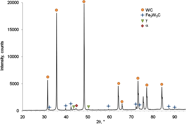
X-ray diffraction pattern of X120Mn12/WC base bimaterial sintered at 1290°C during 60 min
The microstructure of the intermediate layer composed of a M6C network with embedded remaining WC grains and an Fe rich binder with small amounts of Cr and Mn is consistent with the mechanism proposed in the previous article13 for the formation of M6C in model bimaterial, steel (Fe–WC–C)/cemented carbide (WC–Fe–C).
During sintering, the binder of WC base layer is liquid (>1085°C in Fe–W–C system).26 The contact of this C rich liquid with the steel layer induces C diffusion towards the X120Mn12 layer (Fig. 10a). The C enrichment of the X120Mn12 layer near the interface results in the local formation of liquid according to the isopleth section (Fig. 4a). The formed liquid then tends to mix with the WC grains surrounding liquid and move into the WC base layer, by a capillary mechanism. The resulting interfacial mixed liquid with lower C and W contents than the liquid required for local equilibrium with WC particles locally induces the dissolution of WC (Fig. 10b). The newly dissolved C and W tend to diffuse inside the liquid and into the steel layer. The diffusion rate determined in the W–C–Co system is lower for W than for C.27 This leads to the formation of liquid in steel layer and to a W enrichment in the interfacial mixed liquid. Near the interface, the composition of the WC base layer chosen to be located in the WC+L domain during sintering is then shift to the WC+L+M6C domain according to the Fe–W–C ternary system and M6C is formed (Fig. 10c). As temperature and duration increase, the liquid amount increases and enhances WC dissolution and M6C growth. The final microstructure of the interfacial area then consists in remaining mixed liquid and WC grains in M6C matrix consistent with SEM observations. The authors’ observations are consistent with the work of Simchi and Petzoldt on 316L/WC–Co bimaterial who evidenced the formation of an interfacial liquid and M6C carbides during cosintering.12 The use of the same steel for the binder of the cemented carbide and the steel layer may appear as a solution to prevent M6C formation, but in this case the non-equilibrium takes place within the cermet, leading to the transformation of carbides and other effects on the phases distribution difficult to control, as has been observed in the case of cermets (TiC–NbC– 465 stainless steel)/465 stainless steel bimaterial.28
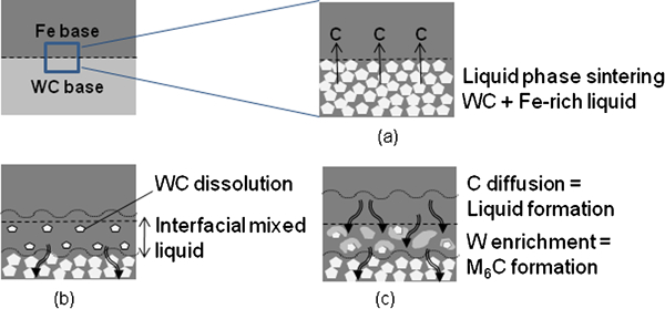
Schematic representation of M6C formation in interfacial area
A different bimaterial architecture was also studied, in which millimetric WC base inclusions were dispersed in a steel matrix. The inclusions were prepared from a thin WC base compact, crushed into millimetric pieces. These inclusions were then debound and presintered at 1050°C in a He–4H2 flow, and then introduced into the compaction die with the X120Mn12 powder.
The interfaces between WC base and X120Mn12 in the sintered samples present two situations (Fig. 11):
M6C phase formation at interface between steel matrix and WC base inclusions after sintering at 1290°C during 60 min in graphite resistor
regions with sparse contacts between the materials. These low cohesion regions may have different origins: the simple consequence of bad contact between inclusion and matrix during compaction (mechanical and geometrical effects), or bad wetting due to the oxidised metallic powder surface (chemical effect)
regions with large formation of M6C phase. M6C appears in the WC base inclusions in the form of continuous blocks embedding some remaining WC grains. In this case, the mechanism described for the model bimaterial, steel (Fe–WC–C)/cemented carbide (WC–Fe–C), can also be applied. The driving force due to thermodynamic disequilibrium between the two materials is enhanced by the lack of W in X120Mn12. Planar limits between ‘not transformed’ and ‘transformed’ areas suggest propagation fronts. M6C formation starts from interfacial regions where the contacts are high between the initial materials, and propagates inwards to the WC base inclusions. In this case, the formation of M6C phase might have harmful consequences, but also results in the formation of strong metallurgical bonding between materials.
Conclusions
This investigation illustrates the case in which the two materials are only compatible in terms on sintering conditions, without considerations of interface equilibrium. In this case, the interface reactivity is high, as the two materials have major common elements but strong composition differences, so that the high driving force promotes large scale transformations.
The three step methodology defined on the model bimaterial proved to be efficient for finding suitable sintering conditions on the studied materials, and for evidencing phenomena which may occur from the interaction between layers at their interface. The mechanism of cooperative liquid and M6C formations in the interfacial region proposed for the model bimaterial is also observed for this two layer component. The results obtained with the Hadfield steel show that results can be extrapolated to new materials. Nevertheless, the C and Mn losses during sintering must be controlled or balanced. An alternative route to cosinter WC base material and X120Mn12 could be the spark plasma sintering. Spark plasma sintering allows a rapid sintering at lower temperatures than pressureless sintering. The use of graphite die during spark plasma sintering experiments is expected to reduce the decarburisation of the samples. The rapid sintering combined with the decrease in sintering temperature is expected to reduce the Mn losses and the applied pressure is expected to improve the densification, particularly of X120Mn12. First attempts of SPS experiments have been performed and must be continued.
Footnotes
Acknowledgements
The authors wish to express their thanks to Eurotungstene Poudres (Grenoble) for raw materials. The authors acknowledge Direction Générale des Entreprises, Conseil Général de la Loire and Saint Etienne Métropole for their financial support of the ‘MULTIMAT’ Project, within the Competitiveness Cluster ViaMéca and CETIM Foundation for its financial support of the ‘Multimaterial and Multifunctional Products’ Project.