
Abstract
In some powder metallurgy part forming, when high compacting loads would require a too large single shrink fitted die, or the inner die diameter is very large but the compaction area is modest, twice shrink fitted dies, which are relatively expensive and complex to build, should be used. In both cases, at any given compacting load, the design should minimise dimensions and stresses. The design targets are minimum die size, optimum intermediate diameter and optimum interference, with maximum stresses on each die item lower than those allowable for the selected materials. In dual mode, for fixed overall dimension, intermediate diameters and shrink fitting interference should enable to maximise the compacting load without exceeding the allowable maximum stresses. In the first part of this work, for cylindrical shapes (circular profile dies) and axisymmetric plane stress problems, dimensions, interferences and stress–strain states have been analytically calculated to optimise doubly shrink fitted dies in the abovementioned sense. In the second part, the same evaluations for axisymmetric generic problems have been carried out by finite element method (FEM) approach integrated in an optimisation procedure. The minimum overall dimensions of the die are presented as a function of the ratio between applied load and maximum allowable stress. Corresponding interferences and optimum diameters have been calculated. Some approximate equations for a quick and handy optimisation are presented. The differences between analytical and numerical results obviously depend on the consideration of the actually stressed length, or compact height, and total die height. The comparison indicates that FEM analyses are needed since analytical calculations generally give low approximations, especially for some die geometries.
Introduction
Usually, the design of a tool for metal powder compaction is based on engineering experience, company know-how, company data (or powder supplier data) on dimensional changes, approximated analytical calculations of overall die dimensions and cost evaluations.
The required initial data include the following:
compact shape, dimensions and tolerances
compaction density
powder mix composition and apparent density
compaction (and radial) pressure
dimensional changes on sintering of the selected powder mix
part number
materials of the different tool items
type and features of the available compaction press.
Independently of dimensional changes, the design targets are diameters of insert and shrink fitting ring, sometimes even number of ring and corresponding diameters and interference (or interferences). Design constraints are: no tensile stresses on the insert, no risk of relative motion of tool items at part ejection, no unwanted alteration of material microstructure caused by heating for assembling and maximum stresses always below the allowable limits.
Powder metallurgy engineers involved in tooling and compaction know that
the inner die diameter d is established on the basis of:
dimension to be achieved after sintering
powder mix formulation
compaction pressure and corresponding spring back on ejection
die rigidity (depending on thickness of both items and constituting materials as well)
sintering conditions and corresponding dimensional changes
the outer die diameter D is established on the basis of:
features of the press and tool holder to be used
internal standards
strength calculations (if and when possible)
cost evaluations
the common diameter between insert and ring (or rings) d1 is established on the basis of:
tool design criteria
required compaction pressure
ratio between radial and axial pressure
stress level evaluations
cost comparisons
the part height h is established on the basis of:
dimension to be achieved after sintering
the die height H is established on the basis of:
compression (or filling) ratio
filling effectiveness
guiding length of the lower punch (or punches).
The optimisation of only once shrink fitted circular dies has been investigated in other papers.1– 4
As a rule, for a correct design, some binding conditions must be fulfilled:
the stresses on the insert should be compressive, even at maximum compaction pressure
the mutual pressure between insert and ring must be high enough to avoid any relative sliding at compact ejection
the temperature to reach, to widen the ring and to introduce in it the insert must be compatible with the required microstructure and properties of the ring material
the required prestressing stresses on the insert and the stresses during compaction on insert and ring (or rings) must always be lower (in absolute value) than the strength properties of the used materials.
The first and second conditions are lower bound for interference determination, while the third and four ones are upper bound.
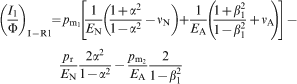
In order to fulfil the first condition, Lamé solution leads to the following formula,1 which is valid also for warm compaction
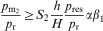
The formula corresponding to the second condition, also valid for once shrink fitted dies, which establishes the minimum interference suitable to avoid any unwanted relative sliding at compact ejection,1 is
The third condition is expressed by the following formulae, which must be satisfied in both cases
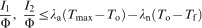
Considering that steels for rings are quenched and tempered before assembling, the highest allowed heating temperature Tmax, at which it is possible to place the insert inside the ring, is ∼550°C. As a matter of fact, a priori, if the calculated interference is very high, we cannot exclude that it could be necessary to cool the insert before assembling. As a rule, due to the physical properties of steels used for rings, without any cooling of the insert, the interference corresponding to the maximum allowable temperature should be1– 4 I/Φ<0·00685.
The fourth condition is an evident structural constraint.
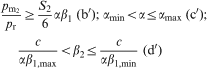
Sometimes, PM part makers are obliged to face an unpleasant situation: the die to be used to compact a given part should be bigger than the corresponding housing on the press. Thin walled ring shaped parts represent typical examples of such possible situation. Ring nuts, the old rotating bands or antilock brake system toothed sensor rings belong to this family of part shapes. From a general standpoint, the critical parameter is the value of the ratio between compaction area of the compact and projected area of the die cavity. If d is the outer diameter of the part and di is its inner diameter, the ratio is given by the formula
 . In the first approximation, the problem of a relatively too large outside part diameter arises when the above ratio is <0·5 and may become serious when it decreases below 0·25. To be complete, it should be added that the outer diameter of the die D in most cases is ⩾4d.
When this problem happens, various solutions are viable:
the use of a larger press, with superabundant tonnage and unwanted additional costs
the use of a ‘slim’ die, with possible intrinsic limitations on the compaction pressure and some risks of premature die failure
the building of a ‘stronger’ die, where the containing radial pressure on the insert is exerted by a couple of relatively ‘slim’ rings.
The latter case, rather infrequent for the complex and time consuming calculations involved, may be the optimum solution to the prospected problem. From a more general standpoint, a single or doubly shrink fitted die could be optimised with different objectives:
to manufacture a die with the minimum outside diameter, with acting stresses always lower than those allowable on the used materials
to manufacture a die with a given outer diameter, always with acting stresses that are the lowest possible, at any given compaction pressure.
The present paper faces the problem of a double shrink fitted die optimisation by means of both analytical and finite element method (FEM) calculations. For simplicity but without loss of generality, it has been assumed that the allowable stress is the same, in absolute value, for both insert and ring materials. In this study, one constraint is supposed to prevail: the stresses on the inner surface of the insert should always be compressive. As in previous studies, this constraint resulted to be more restrictive than that which considers the mutual pressure between insert and ring, generated by shrink fitting, high enough to avoid any relative sliding (between insert and ring) at the compact ejection.
Analytical evaluations
As already stated, once the inner and outer diameters of the die are fixed, i.e. d and D, or, more generally, their ratio d/D, the objective is to find the lowest stress state on the die set. The intermediate diameters d1 and d2 can be selected in order to get a minimum value of the equivalent stress. The calculations should enable to find the diameters and interferences corresponding to the objective. Feodoseev5 demonstrated that in case of single shrink fitting, the condition of lowest and equal Tresca stresses on the inner surfaces of rings, when an inner pressure acts on the insert, is fulfilled if it is d2 = (d1×D)1/2, where d2 is the outer diameter of the inner ring and the inner diameter of the outer ring.
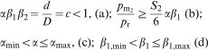
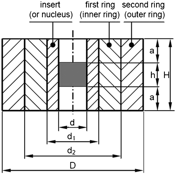
In powder metallurgy part forming, the interferences must ensure the proper functionality of the die, i.e. no tensile stress on the inner surface of the ring, no sliding between tool items at part ejection and maximum interference compatible with the requested microstructure on the materials of both rings. Figure 1 shows a sketch of a twice shrink fitted die. In order to utilise Lamé formulae, the radial pressure is supposed to act on the whole die height, and the friction between rings is neglected. To avoid the presence of tensile stresses at the inner surface of the insert and unacceptable sliding between the insert and the first ring, the following inequality must be fulfilled1,2

 is the mutual pressure between the insert and the first ring,
 is the mutual pressure between the first and second rings, pr is the radial pressure on the inner surface of the insert at compaction end (acting along all length) and β1 is the ratio between the inner and outer diameters of the first ring.
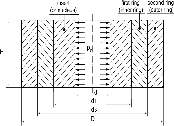
Draft of twice shrink fitted die for analytical calculations
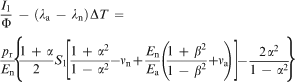
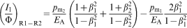
For every reasonable value of dimensions and safety coefficients, the constraint that keeps negative the stress in the insert drives the optimisation analysis. Then, we can impose, in all the subsequent evaluations, the equality symbol in formula (4); in this way,
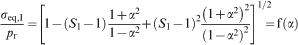
 is no longer an unknown of the problem. For this reason, and taking into account that the maximum equivalent stress always appears on the inner diameter of each item, the ratio between the maximum equivalent stress on the insert σeq,I and the radial pressure on the die pr at compaction end is given by the relation
 , the mutual pressure between the first and second rings
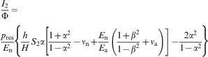
 and the ratio between the inner and outer diameters of the first ring β1 (β1 = d1/d2). The corresponding value of this stress is
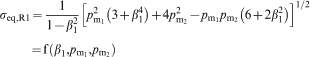
 can be calculated by expression (4) with the equality symbol.
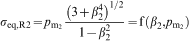
For the second ring (or outer ring), still using Lamé formulae, we get
The optimisation problem can be expressed as
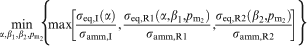
In this work, the allowable values of stress for the different items are supposed to be equal; then, expression (9-1) becomes


 }
}
min {σeq,I}
min {σeq,R1}
min {σeq,R2}
min {σeq,I} with the constraint σeq,I = σeq,R1
min {σeq,R2}with the constraint σeq,I = σeq,R1
min {σeq,I}with the constraint σeq,I = σeq,R2
min {σeq,R1}with the constraint σeq,I = σeq,R2
min {σeq,I} with the constraint σeq,R1 = σeq,R2
min {σeq,R1} with the constraint σeq,R1 = σeq,R2
min {σeq,I} with the constraint σeq,I = σeq,R1 = σeq,R2
Owing to the particular expressions of the equivalent stresses on the items, in order to make the optimisation procedure suitable also to a numerical solution, it has been simplified as follows:
initialise the ratio α to α = αmin
calculate σeq,I(α)
solve the subproblems
min {σ
eq,R1
}→{β
2
,
min {σ
eq,R2
}→{β
2
,
min {σ
eq,R1
}with the constraint σ
eq,R1
= σ
eq,R2
→{β
2
,
 }(1)
}(1) }(2)
}(2) }(3)
}(3)
check the subsolutions in order to have the current minimum M(α)
M(α) = min(M
1
, M
2
, M
3
) M
1
= max{σ
eq,I
, σ
eq,R1
({β
2
,
M
2
= max{σ
eq,I
, σ
eq,R1
({β
2
,
M
3
= max{σ
eq,I
, σ
eq,R1
({β
2
,
 }
(1)
eq,R2
({β2,
}
(1)
eq,R2
({β2,
 }
(1)
)}
}
(1)
)} }
(2)
eq,R2
({β2,
}
(2)
eq,R2
({β2,
 }
(2)
)}
}
(2)
)} }
(3)
eq,R2
({β2,
}
(3)
eq,R2
({β2,
 }
(3)
)}
}
(3)
)}
increase α and go to point 2 until αmax is reached.
The solution is given by choosing the minimum value of M(α) calculated during procedures (i)–(v). At this point, the interferences are calculated by the following formulae, based on previous studies,1–
4 but valid for twice shrink fitting of dies
Results of analytical calculations
When evaluating the interferences corresponding to defined stress levels, the elastic properties of the involved materials must be taken into account. Then, the calculations have been made considering the elastic parameters of Table 1;6– 8 for interferences evaluations, an applied internal radial pressure pr = 200 MPa has been used.
Elastic parameters used in analytical calculations (at room temperature)
Like in previous works,1– 4 the adopted safety coefficient S1 has been posed equal to 2, while the safety coefficients, to account for the impulsive action of the ejection load, are S21 = 10 (like for once shrink fitted dies) between the insert and the first ring and S22 = 6 between the first and second rings. Furthermore, the limits αmax = β1,max = 0·9 have been established to avoid the risk of elastic instability when assembling the items (first ring inside the second one or insert inside assembled rings).3
The results of the analytical calculations are presented in Figs. 2–5.
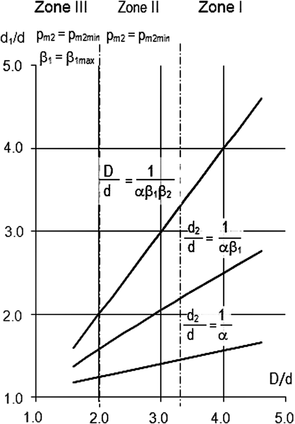
Optimised die diameters and stress level from analytical calculations
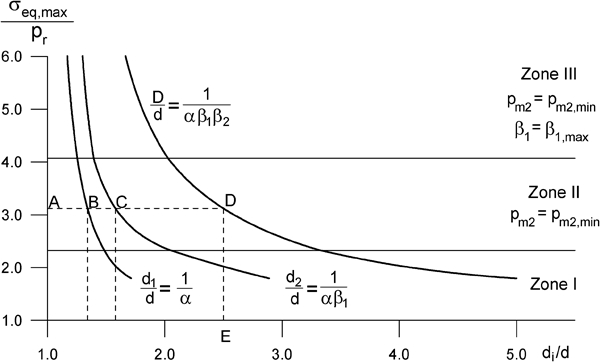
Comparison between single and twice shrink fitted optimised dies
Optimised die diameters from analytical calculations
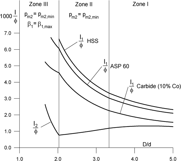
Interferences for different insert materials versus ratio D/d from analytical calculations
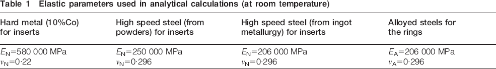
Figure 2 shows three curves, corresponding to the outer diameters of all the items, which define the optimal solutions, calculated as above explained. The diagram can be used considering two optimisation problems: minimisation of the overall dimension D (or, better, D/d ratio) or minimisation of the maximum stresses. In the first case, once established, the allowable stress (point A in Fig. 2), the unknown optimal diameters follow (abscissas corresponding to points B–D). In the second case, fixed the overall diameter (point E), the values of the intermediate diameter can be early evaluated (abscissas corresponding to points B and C).
The optimisation procedure enables to distinguish three zones, depending on the range of D/d ratios:
normal or nearly normal dies, indicated as zone I in the figures, with D/d⩾3·31
lean, or slender, or thin dies, indicated as zone II in the figures, with 2·03<D/d⩽3·31
meagre or very thin dies, indicated as zone III in the figures, with D/d<2·03.
Inside the first zone, namely, for ‘normal’ dies, the optimum diameter ratios are reached when the condition σeq,R1 = σeq,R2 is kept, and it results in σeq,I<σeq,R1. The solutions belonging to the second zone, namely, ‘slender’ dies, stay on the boundary of domain (102); in particular, constraint (10-2) (b′) acts, which establishes a minimum for the mutual pressure
 to avoid sliding between the rings. In this case, it results in σeq,I = σeq,R1 = σeq,R2. Finally, in the third zone, namely, for ‘meagre’ dies, the solutions lie in the subspace characterised by the conditions
 and β1 = β1,max (constraint (10-2), (b′) and (d′)). It results, in this case, in σeq,I = σeq,R2>σeq,R1.
Figure 3 points out a comparison between single and double shrink fitted dies. It can be noted that the maximum stress difference decreases for small values of D/d ratio and tends to become constant for D/d>3·5. Figure 4 shows straight the intermediate diameter values as a function of outer diameter in the optimal condition. The straight line to 45° can be divided into three segments, corresponding to the three ranges of nucleus thickness and ring thickness (normal, lean or meagre dies). Finally, Fig. 5 shows the curves of the interferences versus the die ratio D/d. The ordinate value is limited to I/Φ (%) = 0·685 since, as stated before, this is the maximum interference compatible with the retention of proper metallurgical microstructure of ring materials.1– 4 Figure 5 indicates that the optimum interferences increase dramatically as the D/d ratio decreases below ∼2·5, and that D/d = 2 is the thinnest die that could be produced in safety conditions if high speed steel (HSS) is used for the insert. It can also be noted that the interference between the first and second ring is independent from the insert material because the rings are made of the same material.
Main indications obtainable from analytical calculations
Considering the stepwise increase in stress states, the correct sequence of operations to observe to get a doubly shrink fitted die must be the following:
coupling of the rings with the optimum interference by heating the outer ring to a temperature high enough to permit the free insertion of the first ring
after assembling of rings and cooling to room temperature, machining of the inner surface of the ring set to the diameter corresponding to the required interference with the nucleus
inserting the nucleus inside with the already coupled rings by heating them to a temperature high enough to permit the free penetration of the insert.
As to stress levels on the assembled die, the sequence of steps could be different. However, only the above listed sequence ensures that the stresses on each die item do not exceed, even temporarily, the allowed values. The analytical calculations carried out to find the optimum conditions for twice shrink fitted dies do not allow the proper consideration of:
die height
portion of die height where the radial pressure really acts
constraints among corresponding points on the contacting surfaces.
However, in spite of these limitations, some useful conclusions can be drawn from the results summarised in Figs. 2–5. The insert material may be critical in borderline cases, for instance, when the compact size and the die housing of the available compaction press correspond to D/d<2 (for an inner radial pressure pr = 200 MPa). Within this range, allowable interferences can be achieved only using inserts made of high stiffness materials, such as hard metal. All analytical calculations have been limited to room temperature. However, previous studies3,4 demonstrated that the use of carbide inserts for warm compaction dies requires special attention due to interference ‘fading’ originated by a temperature increase. This special attention, of course, is required also in case of twice shrink fitted dies. Under this aspect, the coupled rings may be considered as a single ring, with the corresponding diameters, and the formulae reported in Refs. 3 and 4 may be used. For completeness, it should be pointed out that double shrink fitting may be helpful to reduce the cost of materials, since a lower hardenability may be enough in case of rather thin rings. This means that less alloyed and less expensive grades of steel could be used for the rings, in comparison with the grade required for a thicker, single ring. As repeatedly stated, the proper consideration of the actual die length and stressed portion of the insert requires the FEM approach. Figure 4 shows that the results of analytical calculations agree with Feodoseev's5 indications.
Finite element method analysis
Following the procedure already applied in previous studies on the stress states of shrink fitted dies,1– 4 a simple shape, with circular cavity, has been investigated. Figure 6 shows a scheme of such a simple die, where the used symbols are also indicated. For simplicity, in the calculations, it has been assumed that the position of the compact at compaction end, and before starting its ejection from the die, is exactly in the middle of the total die height H. The design data are the following:
Draft of twice shrink fitted die for FEM analysis where radial pressure acts on one-third of total length
inner diameter of the insert: d = 50 mm
radial pressure at compaction end: pr = 200 MPa
radial pressure at the beginning of compact ejection: 100 MPa
material of the ring: high hardenability, medium carbon steel, quenched and tempered (for instance, 4340 AISI steel)
material of the insert (or nucleus): HSS, HSS from high alloy powder (Uddeholm ASP 60, now Vanadis 60), hard metal with 10%Co.
The numerical analysis, when compared to the analytical solution, permits to model the problem in a manner more faithfully corresponding to the real situation. The finite element method approach enables to account for the influence of die length on stress distributions inside any die element and that of the portion of total length where the radial pressure acts at the compaction end. Owing to the axial and transversal symmetries, the FEM analysis has been carried out on a quarter of the transversal section of the die, as shown in Fig. 7. The type of finite element here used has been a plane quadrilateral, with eight nodes.
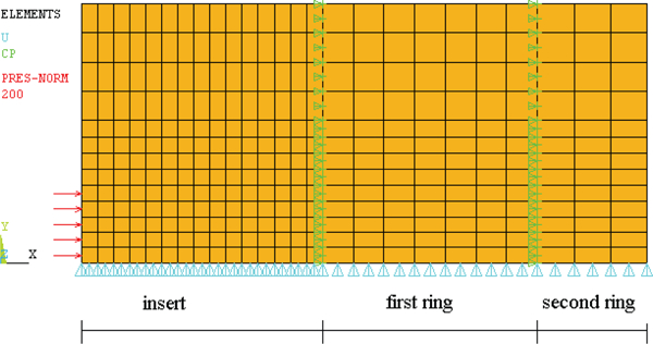
Example of mesh used for FEM analyses
For different values of D, H and h, always defined through their ratios with the inner diameter of the nucleus, a singular value of the diameter d1 has been calculated. This diameter, common to insert and ring, identifies a minimum value of the equivalent von Mises stresses, acting on both die items. The different conditions investigated are listed in Table 2, which displays the corresponding ratios between dimensions.
Values of ratios introduced into FEM calculations
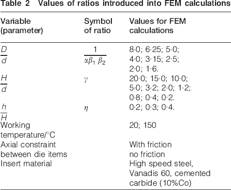
If γ denotes the ratio H/d, the dies can be classified by their aspect ratios as follows:2
As to any possible interaction between insert and rings, two extreme conditions have been hypothesised:
‘presence of friction’ between nucleus and shrink fitting ring, without possibility of relative axial sliding after shrink fitting; this condition has been simulated by binding the degree of freedom related to the axial translation among the coincident nodes of nucleus and ring
‘absence of friction’ between shrink fitting ring and insert, with possibility of relative axial sliding after shrink fitting; this condition has been simulated by removing the preceding constraint.
The optimisation strategy may be outlined through three steps:
initialisation of the design variables α, β1, β2 and
 and definition of lower and upper limits for each variable
run of the one of the optimisation routines implemented into the used FEM code ANSYS
reading the optimal combination of the design variables and minimum and maximum values of von Mises equivalent stresses.
As previously, it has been assumed that the safety coefficient to account for the impulsive action of the ejection load S21 is equal to 10, between the insert and the first ring, but to avoid any sliding between the first and second rings, it has been reduced to 6.
For a given D/d ratio (D/d = 1/αβ1β2), it is possible to find, by FEM, a numerical process apt to determine the optimum common diameter d1, which minimises the highest von Mises equivalent stress. To find the minimum value of the interference, the procedure described in Refs. 3, 4 and 9 has been followed. The selected design variables are the ratios α, β2, β1 = 1/[(D/d) α β2] and
 , while the selected objective function is the von Mises maximum equivalent stress acting on any die item, which must be a minimum. For any condition, that is for any possible combination of parameters listed in Table 2, arbitrary values of α, β2 and
 have been fixed, and then, by the cited methods, the corresponding values of minimum interference and von Mises stress have been found. Thereafter, to find the minimum von Mises’ stress, different values of α, β2 and
 have been analysed. The ANSYS code allows for this process, which requires a parametrical structure of the geometrical model. The right choice of the solution algorithm is fundamental in any optimisation process. This algorithm, used to establish the values of the design variables, should make the solution converge, as quickly as possible, towards the minimum value of the objective function. The ANSYS code includes various optimisation methods, as well as the possibility of using an outer routine, prepared by the user. In the investigated case, the optimisation problem is not so simple because three design variables are assumed, but the objective function is known. Table 2 shows that the total number of cases to be processed is 8×10×3×2×2×3 = 2880. For any combination, in order to determine the minimum interference and the corresponding stresses, two FEM analyses were needed. Considering that to find the optimum values of α, β2 and
 , on the average, at least 30/40 runs were required, it is easy to imagine the very high number of FEM analyses that have been carried out.
Comparison between analytical and FEM results
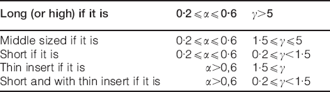
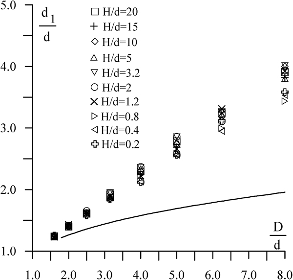
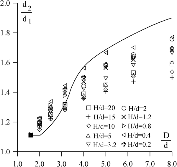
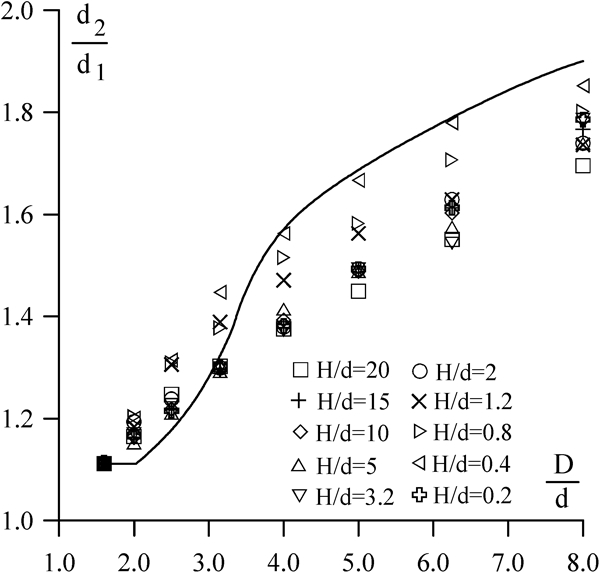
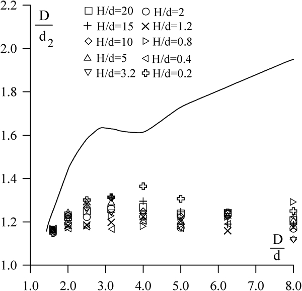
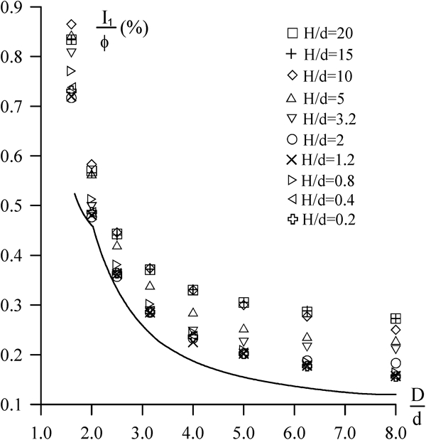
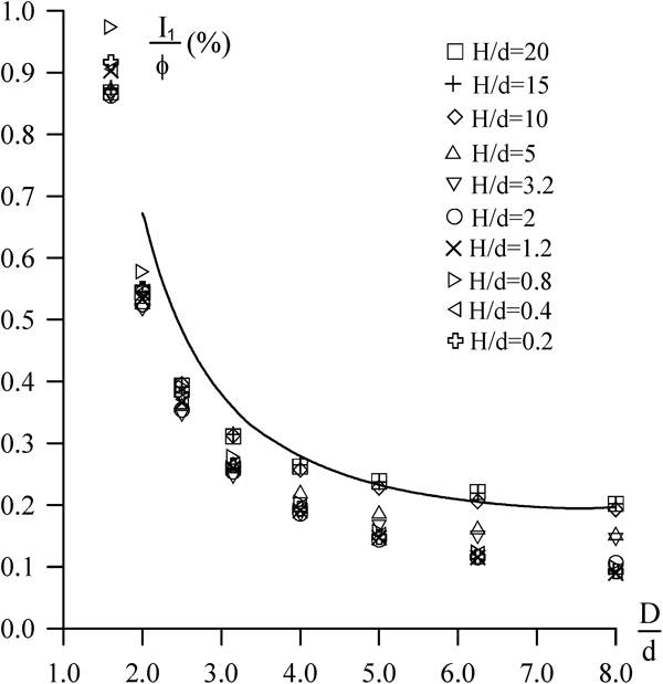
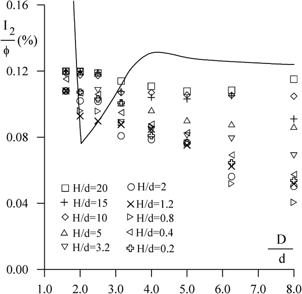
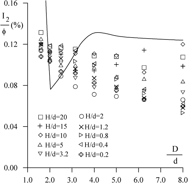
The here presented results refer to room temperature compaction, no mutual sliding at the contact surface between the ring and the insert, namely, presence of friction, die length under radial pressure at compaction end equal to one-third of the total height (h/H = 0·3). The D/d ratio is the quantity always used as the independent variable. Figures 8–19 show the results of numerical optimisation by FEM in case of 10%Co hard metal inserts (even figures) and in case of HSS inserts (odd figures). The results for both materials are very close. For comparison, on each diagram, the continuous lines represent the optimum conditions drawn from analytical calculations. In Figs. 8 and 9, the results of analytical calculations of the ratio between the maximum equivalent stress on the die items σeq.max and the radial pressure on the insert, at compaction end pr, seem to be an ‘average’ value of the different results achieved by the FEM approach. The same figures show that the analytical approach underestimates the stresses for long dies and, on the contrary, overestimates the stresses for short dies. In addition, by FEM, the ratio σeq. max/pi exceeds 5 when it is D<2d.

Ratio between maximum equivalent stress (von Mises) and radial pressure at compaction end; room temperature compaction (carbide inserts)
Ratio between maximum equivalent stress (von Mises) and radial pressure at compaction end; room temperature compaction (HSS insert)
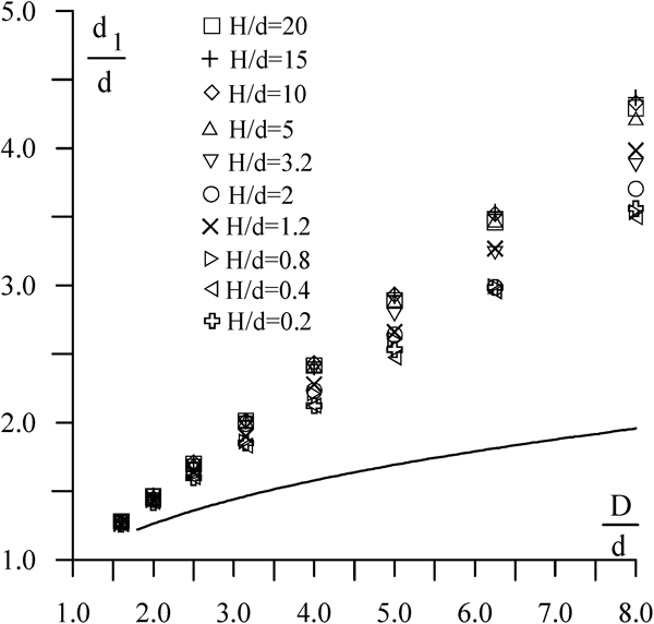
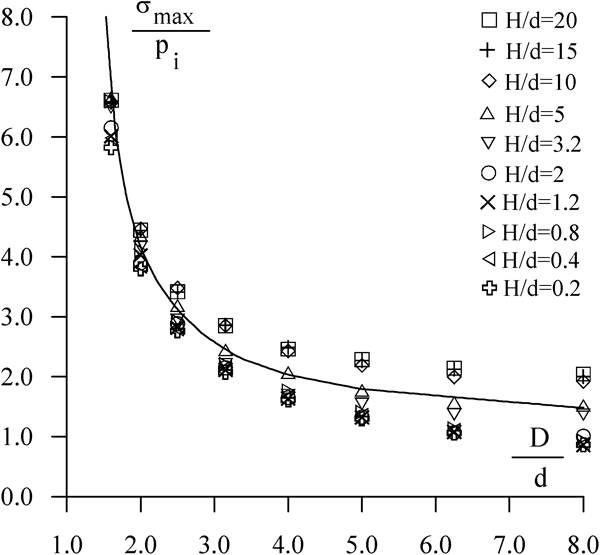
Optimum ratios between diameters of insert (cemented carbide) versus ‘die ratio’ D/d: room temperature compaction
Optimum ratios between diameters of insert (high speed steel) versus ‘die ratio’ D/d: room temperature compaction
Optimum ratios between diameters of first ring versus ‘dies ratio’ D/d: room temperature compaction (carbide inserts)
Optimum ratios between diameters of first ring versus ‘dies ratio’ D/d: room temperature compaction (HSS inserts)
Optimum ratios between diameters of second ring versus ‘dies ratio’ D/d: room temperature compaction (carbide inserts)
Optimum ratios between diameters of second ring versus ‘dies ratio’ D/d: room temperature compaction (HSS inserts)
Optimum interference between first ring and carbide insert versus ‘die ratio’ D/d: room temperature compaction
Optimum interference between first ring and HSS insert versus ‘die ratio’ D/d: room temperature compaction
Optimum interference between first and second rings versus ‘die ratio’ D/d: room temperature compaction (carbide inserts)
Optimum interference between first and second rings versus ‘die ratio’ D/d: room temperature compaction (HSS inserts)
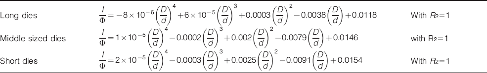
The approximate equations corresponding to the results from FEM analysis, for 2⩽D/d⩽6, are:
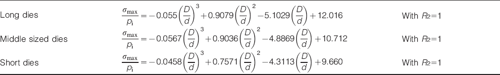
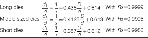
Figure 10 Figures 10 and 11 show a very large difference between the results of analytical calculations and FEM analyses: the relative thickness of the nucleus must be from 20 to 80% bigger than the indications based on Lamé's formulae. In addition, in this case, long dies differ from the short ones: the longer the die, the larger the difference between FEM results and analytical indications. Furthermore, the correspondence between d1/d and D/d may be approximated by linear laws. The equations of the straight lines approximately corresponding to FEM results, for 2⩽D/d⩽6, are:
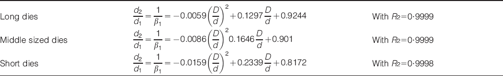
Even Figs. 12 and 13 show a noticeable difference between the results of analytical calculations and FEM analyses: the relative thickness of the first ring must be smaller than the indications based on Lamé formulae for long dies, whereas it must be greater for the short ones. The correspondence between d2/d1 and D/d may be approximated by polynomial equations, such as:
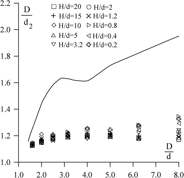
Figures 14 and 15 show the results obtained for the outer ring. The differences between long or short dies are modest, but the FEM results strongly differ from the analytical ones. As a matter of fact, a slope change seems to happen for D/d nearly equal to 3·5. However, remembering that it should be D⩾2d, only one equation may be enough to express the relationship between D/d2 (D/d2 = 1/β2) and D/d, namely, as a first approximation
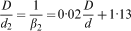 with R2 = 1.
Figures 16 and 17 show the optimum interferences between the first ring and the insert (carbide and HSS respectively) versus the ‘die ratio’ D/d. They indicate that the analytical approach underestimates the interferences between the insert and the first ring in the case of the carbide insert; the differences increase as the D/d ratio and die length increase and can exceed 100%. The polynomial equations approximately corresponding to FEM results are:
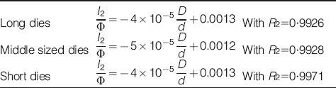
Figures 18 and 19 show the optimum interferences between the first and second rings. It indicates that the analytical approach tends to overestimate the interferences between the first and second rings for long dies, whereas it tends to underestimate I/Φ for the short ones. The optimal interferences should decrease versus the D/d ratio following nearly linear laws. The equations approximately corresponding to FEM results are
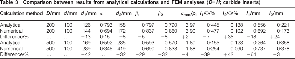
A recapitulatory comparison between results achievable from analytical calculations and FEM analyses, for two die geometries (D = 2d; D = 5d) and D = H, with carbide insert, is presented in Table 3. It shows that at any die geometry, defined by the D/d ratio, all intermediate diameters must be larger than the values drawn from analytical calculations. The largest differences, in absolute value, are shown by the relative interferences between the first and second rings. From a practical standpoint, the significant differences between the outer diameters of the insert should be underlined. Even if the value d1/d = 1·25, from analytical calculations, must be seen as dangerous, due to some risk of elastic instability after shrink fitting, the needed increases of insert thickness imply non-negligible cost increases, especially when using carbide dies. At least partially, the observed differences are attributable to friction on the contacting surfaces. The current experience puts in evidence that no mutual sliding occurs on correctly shrink fitted dies. This fact should remove any doubt about the presence of friction, implicitly considered in the second condition listed in the introduction to FEM approach. For carbide inserts, the presence of friction causes a significant decrease in the minimum interference. The ratio between the minimum interference without friction or with friction respectively is ∼1·5. The minimum value of the maximum equivalent stress, calculated by von Mises hypothesis, notably increases when friction is present. When it is D⩾2d, the presence of friction does not affect the minimum interference, which is always lower than the maximum value allowable in practice. On the contrary, the presence of friction has a strong influence on the lowest value of the maximum equivalent stress: as a first approximation, it appears that through friction the von Mises equivalent stress increases by ∼50% with respect to the value corresponding to the absence of friction on the common surface insert/ring.
Comparison between results from analytical calculations and FEM analyses (D = H; carbide inserts)
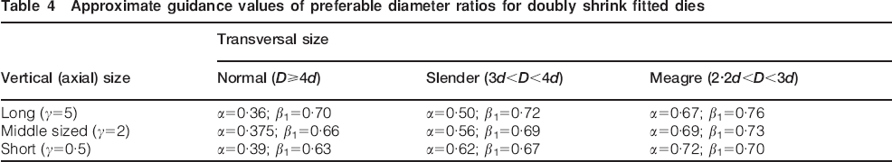
Approximate guidance values of preferable diameter ratios for doubly shrink fitted dies
Conclusions
Finite element method analyses, carried out to find the optimum conditions for twice shrink fitted dies, took into account the die height, the portion of die height where the radial pressure acts and the constraint among corresponding points on the contacting surfaces. The proper consideration of these basic points is not allowed by analytical calculations. Among these parameters, the h/H ratio (always <1 and typically <0·3) is the main factor of remarkable differences between FEM analyses and Lamé formulations. The consideration of this ratio induces local stress increasing on the die insert, so that in order to have a levelling of von Mises’ equivalent stress in the whole die, the insert thickness must be increased. In case of fixed D/d ratio, the thickness of the rings must be reduced. The differences are bigger for larger dies. Furthermore, there is a difference in curves trend for thinner dies. This is because in the analytical results the optimal solutions lie on space variables domain boundary (pm2 = pm2,min and/or b1 = b1,max), whereas in the FEM calculations these conditions never happen (pm2 > pm2,min and b1 < b1,max). The whole of results confirms that die calculation by analytical methods, neglecting actual heights, gives incorrect and dangerous indications, with the risk of dramatically overstressing some die items. Therefore, FEM approaches become necessary and are reliable. At least partially, the cost increase depending on the larger thickness of insert may be compensated by a suitable choice of cheaper material for rings, since the required hardenability is lower. The corresponding costs also decrease. By and large, it appears that the D/d ratio must always be >2. Finite element method analysis indicates that the optimum interferences increase dramatically as the D/d ratio decreases below 2·5 and that D/d = 2 is the thinnest die that can be produced in safety conditions if HSS is used for the insert. It is also interesting to note that the interference between the first and second rings is independent from the insert material. On the other side, D>4d means waste of valuable alloyed steel.
The numerical method supports the distinction among shape classes (long, average or short dies) based on the aspect ratio. When the presence of friction on the insert/ring contact surfaces is considered, the effects are different for different geometries. For long or very long dies, friction causes a strong increase in stresses but a modest decrease in interference. For short or very short dies, the decrease in interference depending on friction becomes trifling. In principle, there may be perplexity about the presence, or not, of friction on the ring/insert contact surface. However, the current experience demonstrates that no mutual sliding occurs on correctly shrink fitted dies. This fact should remove any doubt about the presence of friction. The presence of friction makes unreliable any evaluation of stress states based on Lamé formulae. The results confirm that the design of dies, carried out by analytical calculations, which do not consent to include the heights, leads to incorrect indications that may be dangerous as to die safety, since they impose excessive stresses on die items, not justified by actual functional needs. Again, especially in the case of high pressure compaction, or when specific geometrical constraints are present, the FEM approach becomes inevitable, being the only one reliable. Independently on any difference between analytical calculations and FEM results, the investigation demonstrated that optimum shrink fitting strongly depends on die geometry. Remembering the possible cases, a 3×3 matrix can be used as an example for a quick evaluation of optimum compromise solutions for diameter ratios of various die items. Table 4 shows this approach.
Footnotes
Acknowledgements
The authors warmly thank Professor R. Esposito, former director of the Department of Materials and Production Engineering, ‘Federico II’ Naples University, for his incomparable support in planning and developing the present study.