
Abstract
Sintered steel specimens with density levels of up to 7·6 g cm−3 have been prepared from Cr–Mo and Mo prealloyed powders. The fatigue response has been studied using an ultrasonic resonance testing device that enabled testing up to 109 cycles. It showed that the fatigue endurance strength can be drastically increased by raising the density and that the sintering conditions are effective, though less than the density. The existence of a true fatigue limit was disproved up to 109 cycles for all materials tested, with sintered steels thus being similar to wrought ones. Cr–Mo steels was shown to be superior to Mo alloyed grades due to the markedly finer as sintered microstructure and higher sintering activity. Fatigue crack initiation was found to originate from pores at first at multiple sites, with microstructural orientation being dominant compared to the direction of stress; with progressive loading, some cracks join to form a propagating macrocrack from which the final failure then starts.
Keywords
Introduction
Powder metallurgy (PM) manufacturing is increasingly being used also for precision parts subjected to high mechanical loads in service.1,2 This holds true especially for automotive and transmission components that are fatigue loaded to high cycle numbers, e.g. a connecting rod easily encounters >400 million cycles during service lifetime. Therefore, the fatigue response of sintered steels up to the gigacycle range is of high relevance for such applications, and for both sintered and wrought steels, it has been shown that the behaviour differs considerably from that at lower N, in particular regarding the influence of singular defects.3– 8
Not surprisingly, numerous studies have been carried out to investigate the fatigue behaviour of sintered steels. In part, designers have been keen to obtain reliable data about standard PM steel grades, and in the early 1980s, Sonsino et al. 9– 11 carried out extensive studies on the fatigue of sintered steels with standard density and standard composition; the influence of manufacturing parameters, surface treatments and others was studied. However, fatigue testing was typically limited to 2×10⁶ cycles, i.e. to markedly lower N that is encountered by the parts in service, and the question of the existence of a ‘true fatigue limit’ was not tackled at that time, in contrast to current notions.12 With increasing amount of data, the relationship between fatigue endurance strength and manufacturing parameters became increasingly well established, and Beiss13 showed that, for the designer, determining one very well established S–N curve is usually sufficient since the S–N curves, e.g. for similar materials with different densities, can be derived using the relationships mentioned above with reasonably good reliability, thus overcoming the problem inherent with PM steels that much more parameters affect the mechanical properties than in wrought steels. The same can be stated for the effect of loading conditions such as the mean stress; also, predictability is quite advanced here.14 Some time ago, a public domain database has been established globally,15 which also contains fatigue data that have been screened in order to ensure that only reliable data are included.
In addition to the approach of the designer, who regards the sintered steel more or less as a continuum, investigations on the relationship between fatigue behaviour and microstructure have also been carried out, which is definitely different in PM steels compared to wrought steels, regarding both the porosity and the microstructural homogeneity. This work has been in part summarised by Hadrboletz and Weiss16 and from the fractographic aspects by Dudrova and Kabatova.17 One focus of these investigations has been the microstructural homogeneity or heterogeneity, which is a specialty of PM. It has been reported earlier that Ni–Cu–Mo alloyed sintered steels prepared from diffusion bonded powders, with resulting chemically heterogeneous microstructure,18– 20 exhibit better fatigue properties than similar materials with homogeneous structure,21 which has been claimed to be a consequence of slower crack propagation in the heterogeneous material.
It has been stated unanimously that the single most relevant parameter affecting not only the fatigue endurance but also all the other mechanical properties is the total porosity.8,13,22 Generally, the porosity lowers the strength more than would be attributable to its volume fraction.23 This can be attributed to the specific microstructure of sintered steels: up to relative density levels of ∼6%, the porosity is mostly or completely open and interconnected,24 which means that there is not a ‘Swiss cheese’ structure, with isolated and more or less rounded pores in a continuous matrix, but rather a ‘sponge’ structure with a continuous pore network,25 which means that the sintering contacts are isolated,26 and the area of the real metallic contacts, the ‘load bearing cross-section’ Ac, is markedly smaller than the volume fraction of the metallic phase, which explains the overproportional loss of strength with increasing porosity, as shown e.g. in Salak et al.23 For Mo alloyed steels, a direct correlation between Ac and the normalised fatigue strength has been shown, i.e. empirical parameters are not necessary to predict the fatigue behaviour from the microstructure; however, measuring the load bearing cross-section has been shown to be, and still is, a difficult job.26,27
To improve the fatigue properties of sintered steels, increasing the density combined with high temperature sintering is the most promising approach since the switch from the ‘sponge’ to the ‘Swiss-cheese’ microstructure yields higher Ac and thus better properties for a given density level.25 In the present work, two types of sintered steels, a Mo prealloyed grade and a Cr–Mo type,28 were compacted to various density levels, from the standard density of 7·1 g cm−3 right up to >7·5 g cm−3, using in part high velocity compaction (HVC) techniques,29 differently sintered8,30 and then fatigue tested to the gigacycle range, in order to estimate the effect of the manufacturing parameters on the endurance strength and also to check the slope of the S–N curve at a very high N. The existence of a true fatigue ‘limit’, as indicated by a horizontal S–N curve above a certain N, must be regarded as highly improbable now also for steels, at least with technical materials.12,31 Furthermore, fatigue crack initiation and short crack propagation were studied in detail since the early stages of the fatigue process, i.e. fatigue crack initiation and short crack propagation, are also of high interest.32– 36 It can be assumed that, at very high loading cycle numbers, any propagating crack will, sooner or later, result in the final fracture of the component. Here, the high density variant of the Cr–Mo sintered steel was used, this material being particularly attractive for high performance PM precision parts.
Experimental
The starting powders used were the prealloyed steel powders Astaloy Mo [Fe–1·5Mo (mass-%)] and Astaloy CrL [Fe–1·5Cr–0·2Mo (mass-%)] from Höganäs AB. Natural graphite (0·6 mass-%) as well as a proprietary lubricant was added. The powder mixes were then compacted to different density levels by standard uniaxial compaction (designated ‘NC’), HVC and high velocity double compaction (DHVC),28 with the resulting fatigue test bars being shaped as given in ISO 3928; in parallel, impact test bars ISO 5754 were prepared. The green compacts were sintered following two regimens: the first was for 30 min at 1120°C to follow the pattern of industrial mesh belt furnaces, and the second was for 60 min at 1250°C to simulate high temperature sintering in a walking beam furnace. The atmosphere was N2–10H2 (vol.-%) in both cases with some CH4 added, and standard cooling was afforded, with the cooling rate (linearised from 900 to 300°C) at ∼0·8 K s−1. Despite the very high green density of the compacts, there were no indications of blistering, etc., i.e. the degassing and reduction processes occurred without problems, which is in agreement with the findings given by Danninger and Xu.37
On the sintered specimens, the density was measured by water displacement, with impregnation being afforded using a commercial water stop spray. Standard impact tests were performed on unnotched specimens according to ISO 5754, and metallographic sections were prepared following common procedures by embedding, grinding and diamond polishing using 7 and 3 μm diamond paste; subsequently, nital etching was performed. The hardness value at a 30 kg load was measured in the cross-sections as well as on the punch and die surfaces. The differences observed were marginal, and therefore, the core hardness is given in the following.
Fatigue testing was performed on smooth (unnotched) specimens using a resonance system operating at 20 kHz31,38 in fully reversed push–pull mode (R = −1); the system is schematically shown in Fig. 1a and depicted in Fig. 1b. Since it had been found that the damping effects result in considerable heating of the specimens, with such damping effects being particularly pronounced with porous sintered steels, cooling was afforded using distilled water with a corrosion inhibitor.
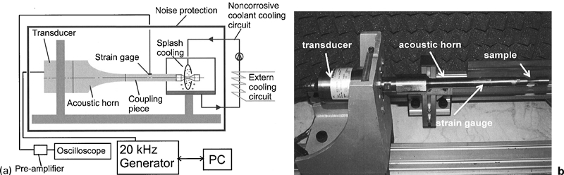
Ultrasonic resonance fatigue testing system
A peculiarity of the resonance testing system used is that the dimensions, in particular the length, of the test specimens, have to be carefully adjusted to ensure perfect resonating, and they depend on the other components of the system and on the Young's modulus of the material to be tested. Furthermore, because of the peculiarities of a resonance system, only the strain amplitude is amenable to direct measurement by means of a strain gauge. For virtually elastic strain amplitudes, as holds here, the stress amplitudes can be calculated using the experimentally determined values of the dynamic Young's modulus.38,39
Therefore, for each material, specimens were machined to 88×5×3 mm parallelepipeds, and the dynamic Young's modulus was measured according to ASTM E1876-99 using a GrindoSonic tester.40 From the results, the optimum length of the fatigue test bars was calculated, and a thread M10×1 was machined at one end of the bar at such a distance from the gauge section of the bar as to ensure the optimum resonating length of the bar.41
In particular, for sintered steels, the state of the surface has been a matter of discussion for a long time. Testing without any machining, in the ‘as sintered skin’, is frequently recommended and is definitely mandatory in the case of uniaxial bending since any change in the surface porosity would strongly shift the fatigue strength level. However, for specimens with a rectangular cross-section, there is always the risk that crack initiation will occur at the edges, and what is really tested then is not the microstructure of the sintered steel but the state of the edges (possibly with burrs). Therefore, special chamfered edge geometries have been developed to avoid cracking at the edges34; the compacts used in the present study had this geometry.
In the case of push–pull loading, the surface state is not quite as critical, but also in this case, surface densification should be avoided. Previous studies with turned specimens that have subsequently been diamond polished to ensure a smooth surface and to eliminate compressive residual stresses have been carried out.8,42 In the present work, a mixed variant was chosen: the die faces of the sintered compacts were milled with a sharp tool to remove the densified areas at the chamfered edges, and then the specimens were polished longitudinally using a rapidly rotating polishing wheel with diamond paste while the bar itself rotated slowly around its axis. Thus, mirror finish surfaces as well as rounded edges were obtained; while by using diamond grit for polishing, both densification of the surfaces and introduction of significant residual stresses were avoided.42
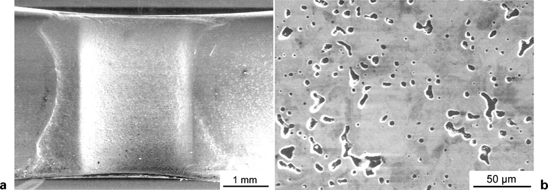
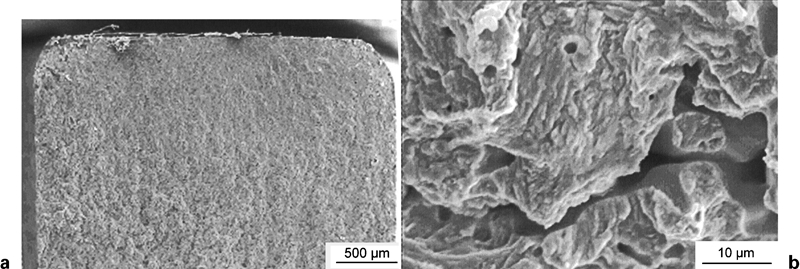
Crack growth specimens were prepared from Cr–Mo prealloy steel compacted by HVC to a green density of ∼7·35 g cm−3 and then sintered for 1 h at 1250°C in N2–H2 atmosphere. A semicircular notch with a 1 mm radius was machined into the centre of the gauge length in order to provoke crack initiation (Fig. 2a; detail in Fig. 2b); thus, the area on the specimen's surface to be analysed using scanning electron microscopy (SEM) under high magnification could be reduced significantly. The surface in the root of the notch was electropolished to eliminate any residual surface damage from the machining operation and to provide a metallographic surface finish that was of sufficient high quality for SEM observation (Fig. 3a and b). The stress in the notch root was measured with miniature strain gauges, as indicated in Fig. 2b.
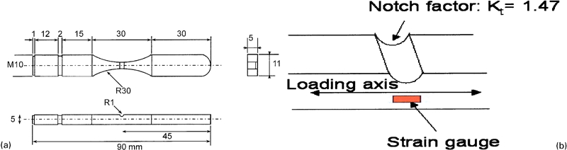
Specimen for crack growth experiments (all dimensions in millimetres)
Notch area after machining and polishing: Astaloy CrL (Fe–1·5Cr–0·2Mo)–0·6C (mass-%) under HVC and sintered for 1 h at 1250°C at density of 7·43 g cm−3
The fatigue crack initiation and the growth of microscopically small fatigue cracks were studied as follows. The notched test specimen was screwed into the tester on one end and cyclically loaded at the stress amplitude of 50% of the fatigue endurance strength of the respective smooth specimen, which had been determined previously as 270 MPa at 109 cycles (see above). The load was then increased stepwise in small increments, with regular inspection in the SEM, until crack initiation or growth occurred and could be identified in the SEM. After consecutive short growth intervals, cycling was repeated. Crack initiation and propagation were observed by SEM, and also the number of visible cracks was counted in regular intervals as precisely as possible. This proved to be a labour intensive and exhausting procedure, but on the other hand, the formation and growth of fatigue cracks could be followed in detail in the low stress–high N range.
Microstructures
In Fig. 4, the as polished microstructures of the Cr–Mo alloyed materials are shown. The significant decrease in porosity in the case of HVC compared to standard uniaxial pressing is clearly evident, as is also the lower size and more rounded morphology of the individual pores, which is also affected by the sintering parameters; detailed qualitative and quantitative metallographic studies on this type of high density materials are described, for example, by Blanco et al. 44 and Stoyanova.45 As described by Dlapka et al.,24 pore closing occurs at density levels of >7·3 g cm−3, at slightly lower density levels for the Cr–Mo prealloyed steels than for the Mo alloyed ones, and therefore, it can be assumed that, for HVC and DHVC specimens, closed porosity prevails, while for the standard compaction, open porosity dominates. For the former materials, this should result in a pronounced increase of the load bearing cross section Ac 24,25,43 and in accordingly improved mechanical properties.
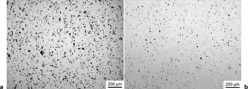
Metallographic sections (as polished) of sintered steels compacted to different density levels, sintered for 60 min at 1250°C in N2–10H2 (vol.-%)
There are, however, also considerable differences in the matrix microstructures, as visible from Fig. 5: regardless of density and sintering parameters, the Mo alloyed steel exhibits the typical coarse upper bainite microstructure, which is characteristic for Mo alloy steels in the as sintered state and is not too beneficial for the mechanical properties, resulting in considerable tendency to large cleavage areas.27,46
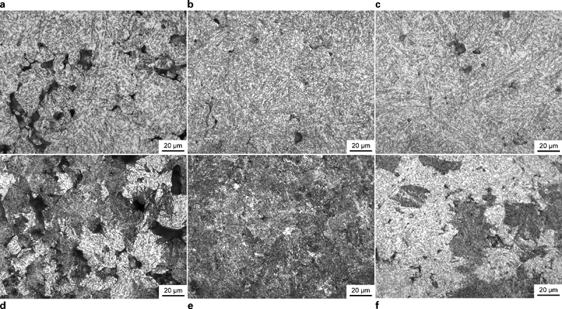
Metallographic sections (nital etched) of sintered steels, compacted to different density levels, sintered for 30 min at 1120°C or for 60 min at 1250°C in N2–10H2 (vol.-%)
For the Cr–Mo alloyed variant, in contrast, a mix of coarse upper and fine lower bainite is typical, which also results in higher hardness of the latter material. Here, it is also evident that the density and, in particular, the sintering temperature play a major role by influencing the carbon loss during sintering, which is, to some extent, affected by the density and early pore closure resulting in less complete carbothermic reduction of the oxides and thus in lower carbon loss,37 the effect of which, however, was not confirmed by C analysis in the present study (Table 1). It can rather be assumed that the methane added to the atmosphere causes slight carburization, which, not surprisingly, is more pronounced at lower density. At higher sintering temperatures, a more complete reduction of internal oxides also occurs, consuming more carbon47– 49; furthermore, in the same furnace at standard conditions, cooling from high temperature furnace tends to be slightly slower than from 1120°C. The pronounced effect of carbon content and cooling rate on the microstructural formation in Cr–Mo prealloyed steels has been shown, for example, by Stetina et al. 50 and Dlapka.51 In any case, however, the formation of a fine lower bainite in Cr–Mo steels should be preferable compared to the coarse upper bainite in the Mo prealloyed grades, and better mechanical properties can be expected from the former materials.
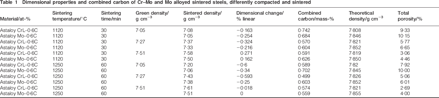
Dimensional properties and combined carbon of Cr–Mo and Mo alloyed sintered steels, differently compacted and sintered
Dimensional and monotonic mechanical properties
In Table 1, the dimensional properties of the specimens are given. The theoretical (pore free) density was calculated assuming that carbon was contained as cementite and that, for the metallic alloy elements, the rule of mixture was applicable, which holds well for Mo but is not quite correct for Cr, as described by Wever.52 Nevertheless, the resulting error was regarded negligible.
From the results, it stands out clearly that the HVC techniques are well suited for obtaining density levels exceeding those commonly encountered by standard or also warm compaction. When comparing the materials, it is evident that the Cr–Mo steels were pressed to slightly lower green density levels compared to the respective Mo prealloy grades, as a consequence of the higher alloy element content, in atomic per cent Astaloy CrL containing about double as much metallic alloy elements Cr+Mo as Astaloy Mo (1·73 at-% versus 0·89 at-%). However, after sintering, the density trend is reversed; for all manufacturing parameters, Cr–Mo steel offering higher density and lower porosity than the respective plain Mo alloy grade, up to 7·6 g cm−3, is attained. This underlines the high sintering activity of Cr–Mo prealloyed steel grades in particular at higher temperatures, as also described, for example, by Kremel et al.53
Not surprisingly, the higher density attained by HVC strongly affects the mechanical properties (Table 2). While the hardness increases markedly but not dramatically (for Astaloy CrL from ∼230 HV30 at 7·1 g cm−3 to ∼300 HV30 at 7·6 g cm−3), the increase in the impact energy must really be regarded spectacular: between the values for 7·1 and 7·6 g cm−3, typically a factor of 3 is found, which underlines that not only the reduction of the total porosity but also the transformation from interconnected to isolated pores strongly promotes interparticle bonding, indicated by a drastic increase in the load bearing cross-section Ac.25,43
Monotonic mechanical properties of Cr–Mo and Mo alloyed sintered steels, differently compacted and sintered
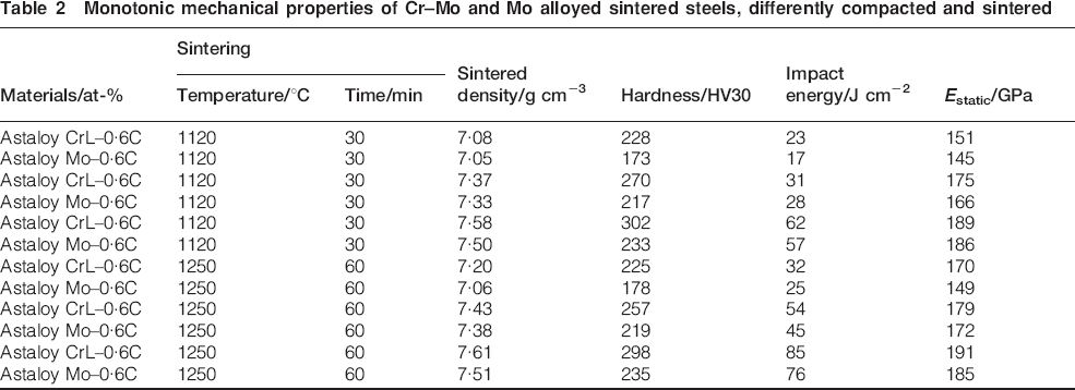
When comparing the hardness and impact energy values of the two steel grades, the superior quality of the Cr–Mo prealloy steel is evident in all cases. The higher hardness can be attributed to the matrix microstructure, as visible from Fig. 5: not surprisingly, the finer structure of Cr–Mo steels results in higher hardness for a given density level than the coarse upper bainite in Mo alloy steels. However, it should be noted that, in the present case, the higher hardness of Cr–Mo steels does not result in lower impact energy, as would be expected from wrought steels, but that higher hardness and higher impact energy are recorded. This can be attributed in part to the matrix microstructure but is also an indicator for the higher sintering activity of Cr–Mo prealloy powders; similar effects have been observed with warm compacted 3Cr–0·5Mo (mass-%) prealloy steels.53 The higher sintering activity can also be deduced from the values for Young's modulus; for both the static modulus and the dynamic one, Cr–Mo steel exhibits slightly higher values than the Mo alloyed one, and the difference is larger than would be expected from the density difference.40
Fatigue properties
In Fig. 6, S–N plots (Wöhler diagrams) are shown for the different materials. It stands out clearly that, at up to Nmax = 109, there is nothing like a true ‘fatigue limit’, i.e. a horizontal section of the S–N graph at higher N; all S–N curves consistently drop with increasing N. This holds irrespective of the density level, i.e. even for very high density sintered steels, there is no fatigue limit, which supports the statement given by Sonsino12 that, also for wrought steels, ‘the existence of a fatigue limit is an illusion’. In all cases, the fracture in specimens occurred also in the loading cycle range of N = 107–109, which clearly shows that testing up to Nmax = 107, as commonly performed for wrought steel as well as for PM steel and even given in standards, is insufficient for obtaining reliable data if the respective components are loaded up to significantly higher cycle numbers; in this respect, there is virtually no difference between sintered and wrought steels.
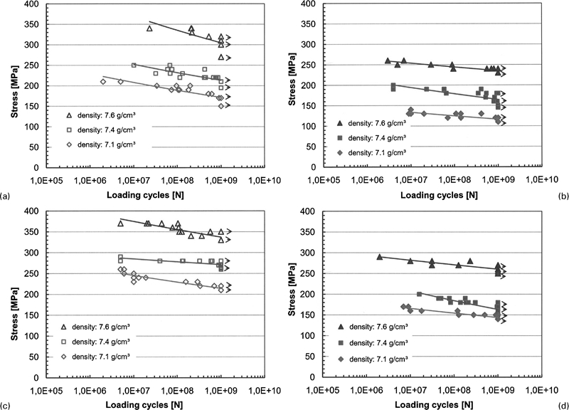
S–N plots (Wöhler diagrams) of Cr–Mo and Mo prealloyed sintered steels: smooth specimens at 20 kHz and push–pull loading, R = −1
The fatigue endurance strength data at Nmax = 109 are given for the as sintered materials in Table 3, together with sintered density and the dynamic Young's modulus, as measured by the GrindoSonic technique (it should be noted that there is a very satisfactory agreement between the static and the dynamic moduli when considering, in principle, the slightly lower values of the former, as a consequence of the isothermal measurement versus adiabatic for the dynamic modulus40). Here, it stands out clearly that the higher density obtained by the HVC compaction techniques is definitely beneficial for the fatigue endurance strength, with significantly higher values being recorded especially at the highest density level. Moreover, the sintering temperature is of considerable importance; 1 h sintering at 1250°C results in generally higher fatigue endurance strength levels. Finally, the matrix material also plays a major role: at least in the as sintered state, the Cr–Mo steels yield markedly better endurance strength levels that cannot be attributed to the slightly higher sintered density but are related to their finer, more favourable microstructure (Fig. 5).
Fatigue endurance strength (50% survival probability at 109 cycles) and dynamic Young's modulus of Cr–Mo and Mo alloyed sintered steels, differently compacted and sintered
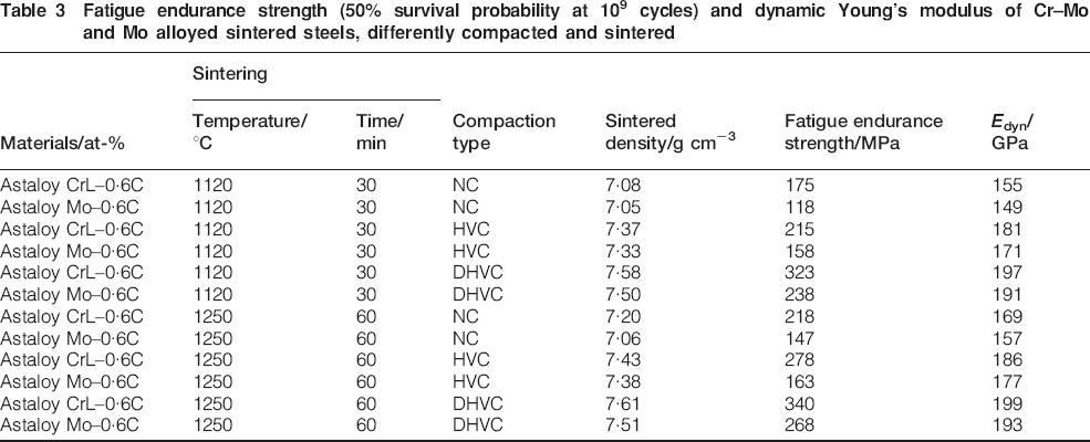
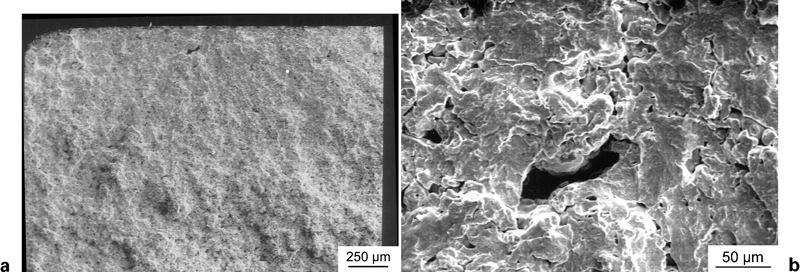
Fractographic investigations (Figs. 7 and 8) showed that crack initiation occurred mostly in the near surface/subsurface regions, single larger pores or pore clusters being discernible as initiation sites, which is in agreement with observations on standard density sintered steels.7,54 It also confirms that the effects of singular defects such as inclusions,55 which were hardly ever found here, or, in the case of sintered steels, porosity heterogeneities, are more effective the higher the loading cycle number is, i.e. in the gigacycle range, such singularities are particularly critical.
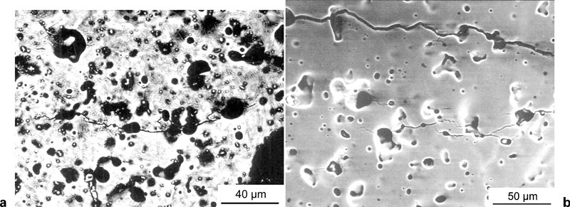
a, b Astaloy CrL–0·6C (mass-%), 7·08 g cm−3, sintered at 1120°C, fractured at 180 MPa, 6·11×108 cycles
a, b Astaloy CrL–0·6C (mass-%), 7·58 g cm−3, sintered at 1120°C, fractured at 320 MPa, 5·2×108 cycles
Crack growth studies
Nucleation of cracks
As shown in Fig. 3, the notch root of the crack growth specimen had a smooth, defect free surface. For these studies, the Cr–Mo prealloy steel was chosen because of its better overall performance, and the medium density level (target 7·4 g cm−3) was selected.56
In Fig. 9, the notch root is shown after loading at moderate stress but at fairly high loading cycle number (in contrast to the conditions chosen, e.g. by Kabátová et al. 57). Here, it can be seen that cracks are initiated at pores, as would be expected for sintered steels. It is, however, also visible that, in this early stage of crack initiation at low loading stress levels, the microcracks are oriented virtually in all directions if adjacent pores can be joined by them. This indicates that, in this stage of the fatigue process, the crack initiation is sensitive mainly to the microstructure, which means the local pore structure, of the materials and not so much to the direction of the applied stress. The cracks observed here are all ‘small cracks’, which were defined as cracks with a length of <150 μm since this is the diameter of the largest powder particles.
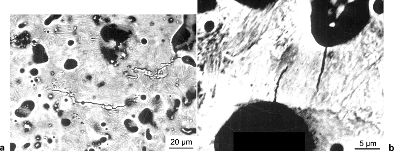
a, b specimen as in Fig. 3, tested at 211 MPa for N = 2·3×108 cycles: vertical axis indicates loading direction
Growth of small cracks
With increasing stress amplitude and loading cycle number, the cracks oriented parallel to the stress axis were observed to slow down and finally stop, while on the other hand, some microcracks oriented perpendicular to the stress axis joined to form a main crack, as shown in Fig. 10.
a, b specimen as in Fig. 3, tested at 242 MPa for N = 1·86×109 cycles: vertical axis indicates loading direction
For a given test run, the number of cracks observed in the investigated area is plotted as a function of the loading cycle numbers, the stress amplitudes being varied during the test run as shown in Fig. 11. Here, it can be observed that, in the early stage of crack initiation, the number of small cracks increases with increasing loading cycles and stress amplitude. After several 108 cycles at moderate stress amplitude, some of them stop, and some of them grow and mostly coalesce; therefore, at the highest stress amplitude, the number of cracks decreases.
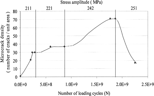
Number of small cracks as function of loading cycles and stress amplitude
It can thus be concluded from the results that initiation and growth of small cracks in the early stage of fatigue are mainly sensitive to the microstructure of the materials rather than to the loading direction. Here, at the early stage of crack initiation, the number of small cracks depends not only on the material and loading parameters but also on the number of loading cycles; during protracted loading, more cracks are generated. If cyclic loading is further continued, especially at higher loading amplitudes, the fatigue cracks become more sensitive to the loading direction. Some cracks oriented parallel to the stress axis stop, and some microcracks that are oriented ‘favourably’, i.e. perpendicular to the stress axis, join to form one larger crack, typically a ‘long crack’ >150 μm. It has been observed, however, that even joining of several initial cracks does not necessarily result in a propagating crack: in one particular case, a crack with a length of 211 μm was observed to be non-propagating at the stress level of 251 MPa. This result confirms the findings given by Weiss et al. 39 and Suresh and Ritchie58 in that short cracks tend to grow at lower stress intensity amplitudes than long ones do, i.e. the surprising and seemingly inexplicable effect that several short cracks grow and merge into one long crack which then stops can happen; propagating cracks thus turn into non-propagating ones.
Conclusions
Since many PM precision components are fatigue loaded up to N>108 cycles, studying the ultra high cycle (gigacycle) fatigue behaviour of sintered steels is of decisive importance, in particular since for sintered steel, as for wrought steel, the existence of a true ‘fatigue limit’ at N>106 is highly improbable. For gigacycle fatigue testing, the ultrasonic resonance technique proved to be well suited, offering the chance to establish S–N curves in reasonably short times. It also showed that rectangular test bars ISO 3928, with rounded edges, can be successfully employed if proper surface preparation is performed, especially diamond polishing to avoid both surface densification and introduction of compressive residual stresses. In all cases, the S–N curves have indicated that, at least up to 109 cycles, a true fatigue limit does not exist for the sintered steels investigated here.
The S–N graphs also confirm that a higher density, as attained by HVC techniques, significantly improves the fatigue endurance strength, by up to 100% compared to standard uniaxial compaction, which can at least in part be attributed to the transition from interconnected to isolated porosity. Moreover, the sintering route is of relevance; higher temperatures combined with longer isothermal soaking times resulted in significantly better endurance strength values. Finally, the material chosen also plays an important role; in the as sintered state, the fine upper/lower bainitic microstructure of Cr–Mo prealloyed steels resulted in markedly higher fatigue strength levels than the uniform coarse upper bainite in the Mo prealloyed materials.
Fatigue crack growth studies have shown that ultrasonic resonance fatigue testing is also well suited to study the fatigue crack initiation and early crack propagation in sintered steels, since high loading cycle numbers are attained at reasonably short times. Interrupting the fatigue testing in regular intervals and studying the loaded surface proved to be a laborious task but is feasible if crack initiation is concentrated in a small area by suitably selecting the specimen's geometry. The tests revealed that, in the initiation stage, crack formation is controlled mainly by the microstructure, i.e. the local pore geometry, the stress direction being of secondary relevance. Only after extended testing, and especially at higher stress amplitudes, the stress direction becomes relevant: those cracks that are oriented perpendicularly to the applied stress grow and coalesce to long cracks, which, however, not necessarily all propagate to the final fracture.
Footnotes
Acknowledgements
This work has been carried out within the international project ‘Höganäs Chair’ organised and financially supported by Höganäs AB, Sweden.