
Abstract
This study aims to determine optimum sintering and heat treatment parameters of powder injection moulded Nimonic-90 powder parts. Determination of optimum heat treatment conditions for sintered parts aimed to achieve maximum densities, and the microstructure and mechanical properties of the produced parts were characterised in sintered and heat treated conditions. Injection moulding feedstock was prepared by mixing Nimonic-90 powder with a multicomponent binder system. After moulding, the samples were subjected to a debinding process that consists of solvent and thermal steps. To determine the sintering temperatures, the debinded samples were subjected to differential scanning calorimetry analysis, and then they were sintered at various temperatures under high level vacuum. After sintering, density measurements and optical microscope examinations were performed. The highest density values were determined for the samples that were sintered at 1330°C for 3 h. Different aging treatments were performed on the samples that achieved the highest sintered density, and the microstructures and mechanical properties were then characterised. It was determined that heat treatments had a beneficial effect on the mechanical properties of the material. Though the mechanical properties of the injection moulded materials produced were lower than the wrought Nimonic-90 materials, they have superior mechanical properties compared with cast Nimonic-90 alloys.
Introduction
Superalloys are a class of high temperature resistant alloys based on Ni, Ni–Fe or Co. Superalloys exhibit an excellent combination of strength and corrosion resistance at both cryogenic and high temperatures.1 Nickel based superalloys have the most extensive application area of all the classes mentioned. Nickel based superalloys have complex compositions designed to give good high temperature properties and find wider use than other alloy systems at similar temperatures.2 Nickel based superalloys are the most commonly used materials for gas turbines, aircraft engine components, critical parts for jet engines, rocket engines, nuclear materials, tool materials and hot working dies for metal parts.3 Nimonic alloys are one class of nickel based superalloys developed to give superior creep resistance and are commonly used in wrought form. Nimonic type alloys gain their superior high temperature properties basically from the precipitation of Ni–Al–Ti compounds within a Ni–Cr matrix.4 These intermetallic precipitates (γ′) have an ordered cubic L12 structure, and the chemical formulation of these phases is Ni3(Al, Ti). γ′ phase is aluminium rich in most nickel based superalloys and titanium rich in most nickel–iron based superalloys.5,6
Traditionally, production of superalloy components begins with the fabrication of large ingots, and these ingots are used in three major production methods to obtain final products. These methods are remelting and investment casting, remelting to produce suitable ingot and then forging, and remelting and producing superalloy powders.7 Slow cooling rates, which are typical of conventional casting, lead to chemical segregation during solidification and, therefore, deterioration of material properties. Rapid solidification associated with powder metallurgy products provides homogeneous microstructures, fine grain structure and enhanced properties. Recently, powder injection moulding (PIM) of superalloys for a variety of gas turbine engine parts has attracted attention.8– 12 Injection moulding makes it possible to produce metal and/or ceramic parts with quite accurate dimensions and a fine grained structure without defects and better mechanical properties. It also increases material utilisation, which can be as high as 95%; it reduces labour content of production by a factor of 3 or more, and capital investment barriers for entry are lower.13 The density of products prepared by single stage moulding and then sintering with injection moulding is higher than those of the products prepared by conventional methods of pressing and sintering, and the strength obtained is close to that of cast and rolled metals.13
Nickel based superalloy powders can be successfully processed by PIM.14 New applications and materials are continually being added to the range fabricated by PIM.15 On the production of nickel based superalloys by injection moulding, a number of studies have been carried out.8– 12,14– 17 However, current use of injection moulded superalloys is limited partially due to insufficient property data.17 In particular, published property data for injection moulded Nimonic-90 alloy are almost non-existent.
In the present study, the Nimonic-90 powder parts have been produced by the PIM method as an alternative to normal production methods. Studies were focused on specifying optimum sintering and heat treatment parameters for injection moulded materials, and then characterisation of materials was carried out. Thermal analysis and metallographic techniques were employed to sintered tensile bars to investigate the sintering behaviours. The tensile and hardness properties of the sintered products were evaluated in the heat treated condition. Powder morphology and fracture surfaces of moulded, debinded, sintered and heat treated samples were analysed using scanning electron microscopy (SEM).
Experimental
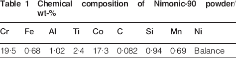
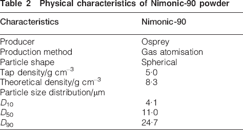
Nimonic-90 superalloy powder used in this study was supplied by Sandvik Osprey Ltd. and was produced by high pressure inert gas atomisation. The powder chemical properties and physical characteristics are given in Tables 1 and 2. Particle size distributions were determined on Malvern Mastersizer equipment and are shown in Fig. 1; these indicate that the distribution of particle sizes is suitable for PIM. The morphology of the powder, observed using SEM, is given in Fig. 2. The gas atomised Nimonic-90 superalloy powder is spherical in shape.
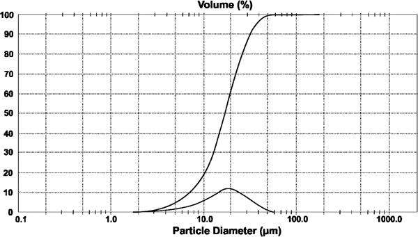
Particle size distribution curve of Nimonic-90 powder
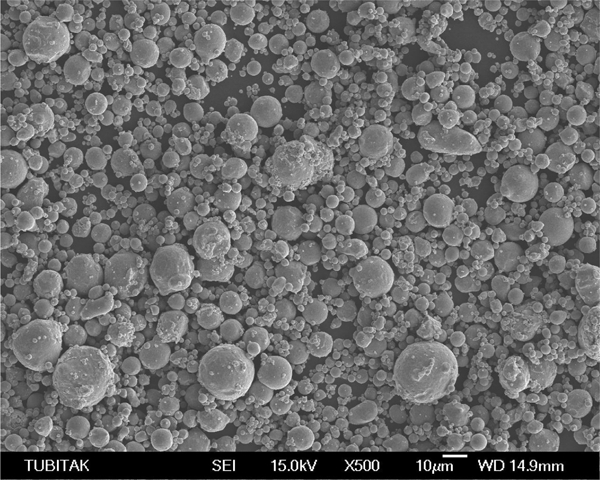
Image (SEM) of Nimonic-90 powder
Chemical composition of Nimonic-90 powder/wt-%
Physical characteristics of Nimonic-90 powder
The feedstock contains 60 vol.-% volume fraction of Nimonic-90 powder and 40 vol.-% of binder. The Nimonic-90 powder was mixed under vacuum environment for 30 min at 170°C with paraffin wax, carnauba wax, polypropylene and stearic acid; the multicomponent binder system was mixed in a specially designed blender. The feedstock was granulated by hand and was injection moulded into a die that was prepared in accordance with the MPIF-50 standard. In the moulding step, the injection device's barrel and nozzle were heated to 170°C; the moulding pressure employed was 12·5 MPa, with 20 s holding time. The injection moulded tensile samples were then debinded by a two-step debinding process. The first step of the process is solvent debinding, and the samples were held in heptane at 60°C for 6 h to remove paraffin wax, carnauba wax and stearic acid. After solvent debinding, the samples were subjected to the second step, which is thermal debinding process. The cycle of thermal debinding process is presented in Fig. 3. This stage was carried out under a high purity argon atmosphere with 2°C min–1 constant heating rate. At this stage, presintering of the samples was provided by holding them at 900°C for 1 h; thus, the shape of the samples was maintained until the sintering stage.
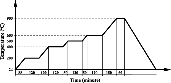
Thermal debinding schedule
To determine phase transformation temperatures and sintering behaviours, debinded samples were examined by differential scanning calorimetry (DSC). Analysis by DSC was performed using a Setaram DSC (model-131) device in a high purity argon atmosphere at a flow rate of 100 mL min–1, with 10°C min–1 heating rate up to 1350°C. Al2O3 was used as a reference material. Sintering operations were realised at different temperatures between 1260 and 1330°C for different periods of time (1–3 h). All the sintering operations were carried out on a Protherm brand furnace with a 10°C min–1 heating and cooling rate under a 10−3 Pa vacuum. The vacuum was maintained during cooling until the furnace temperature had fallen to 150°C. Depending on the binder removal and sintering processes after sintering, it was found that the change in dimensions of all tensile samples occurred in a ratio of 16–18% linear shrinkage (Fig. 4).
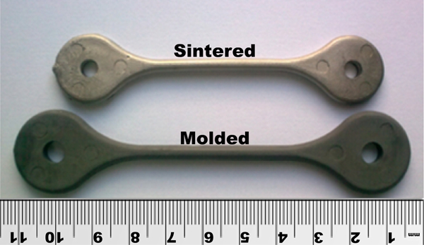
Tensile samples after moulding and sintering stages
After sintering, the density of the samples was measured with Precisa XB 320 brand equipment according to the Archimedes water displacement method. Polished and etched optical microscope images were taken by a Nikon (Lp-1200-Elipse) microscope. After grinding and polishing operations, the samples were etched using a mixture of HCl, H2O2 and ethanol. Microhardness measurements of the sintered materials were performed on a Shimadzu brand device using the Vickers scale, applying 100 g load for 10 s. After the samples had been subjected to a solution treatment process designed for forged Nimonic-90 materials,18 they were aged at 705°C for different times under an atmospheric environment. The effect of the aging treatment was followed by hardness measurements. X-ray diffraction (XRD) analyses of the starting powder and the sintered and aged parts were carried out on a Rigaku-XRD 6000 device using Cu X-ray tube (λ = 0·15405 nm) and with a 0·02/0·4 s scanning step.
Both sintered and heat treated samples were subjected to tensile tests on a Shimadzu (AG-X 50 kN) tensile testing device with a constant crosshead speed of 1 mm min–1. At least three samples were tested under the same conditions to guarantee the reliability of the results. Finally, the microstructure was examined by a JEOL (JSM 6060 LV) SEM with EDX analysis. The carbon values of the heat treated samples were measured by a carbon/sulphur combustion analyser (Horiba/Emia, Japan).
Results and discussion
In order to determine the appropriate sintering temperature range for Nimonic-90 samples produced by PIM, the curves obtained from the DSC analysis shown in Fig. 5 were used. As can be seen for Nimonic-90 powder, the melting begins at ∼1318°C and continues up to 1350°C. It is reported that the melting range of wrought Nimonic-90 materials is between 1335 and 1360°C.19 In this study, the solidus temperature is at a lower level because the powder material has a much higher specific surface energy than the bulk material. According to the data obtained from DSC analysis, the sintering temperature range was specified as 1260–1330°C.
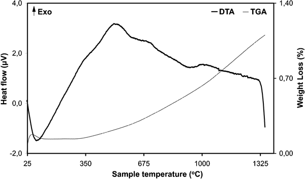
Differential scanning calorimetry curve of Nimonic-90 powder
Relative density values obtained according to the Archimedes water displacement principle are shown in Fig. 6 for samples sintered for 1 h (Fig. 6a) and 3 h (Fig. 6b). Density values increase in parallel with the increment of temperature. The highest relative density of sintered samples was obtained at 1330°C for 3 h, while sufficient densification could not be obtained below the values of 1310°C for 1 h. After 3 h sintering at 1330°C, the value of relative density reached 97·3%. A higher relative density was obtained at the same temperature for longer times. For example, a sample sintered at 1300°C for 3 h reached 96·0% relative density, while at the same temperature, the sample sintered for 1 h reached 90·7% relative density. Nobrega et al. 20 consolidated two different Nimonic-90 powders by PIM that had different particle shapes produced by different techniques: gas and water atomisation. Parts were then processed by plasma assisted debinding and sintering in a reactor held at 1310°C for 1 h. They reported that in this process, relative density reached to 94·8%.20 In the present study, sintering for 1 h at 1310°C gives a relative density of 96·1%. The driving force for sintering process is a decrease in surface energy. It is known that smaller powder particles provide higher surface energy, and so higher density values can be reached.21 Accordingly, in the current study, the moulded samples reached higher relative density at the same temperature in a shorter period of time than the sample sintered under the same conditions in the earlier study.The difference was attributed to the half smaller size of the powder used in the current study.
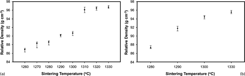
Relative density values of sintered samples at different temperatures for different time periods
Optical images, which were obtained from samples after polishing without etching, in order to get information about the quantity of porosity of the sintered samples, are shown in Fig. 7. The pores remaining in the part are small and spherical in shape, and they were not related to each other.22 When images were analysed, the results were in accordance with the above statement that the pore structure was spherical and that the pores were not interconnected. Figure 7 shows that the pore volume is very high in images of samples sintered at lower temperatures than those at 1310°C, corresponding to low density results. In particular, the image of the sample sintered at 1260°C for 1 h shows that only neck formation was completed among the particles. On the other hand, in the sample sintered at 1260°C, as mentioned above, the average grain size decreased at the same temperature, and for the same time, a good example of a higher density could be achieved. When microstructures are analysed, it is seen that around the smaller size particles, effective bonding and thus high densification were found, whereas the bonding was less and large pores were abundant around large particles. Figure 6 shows that there was a remarkable increase in density when sintering was performed at 1310°C or higher temperatures. According to the data obtained from DSC analysis, the solidus temperature of this alloy is 1318°C. Based on these data, it is thought that when sintering above 1310°C, the super solidus liquid phase sintering mechanism is active. Looking at the image of the sample sintered at 1330°C for 3 h, which reached the highest relative density, it is seen that the amount of porosity and the pore size are smaller than those seen in other samples. In sintering processes carried out at the same temperature for varying periods, it was determined that reducing porosity leads to higher density at longer times.
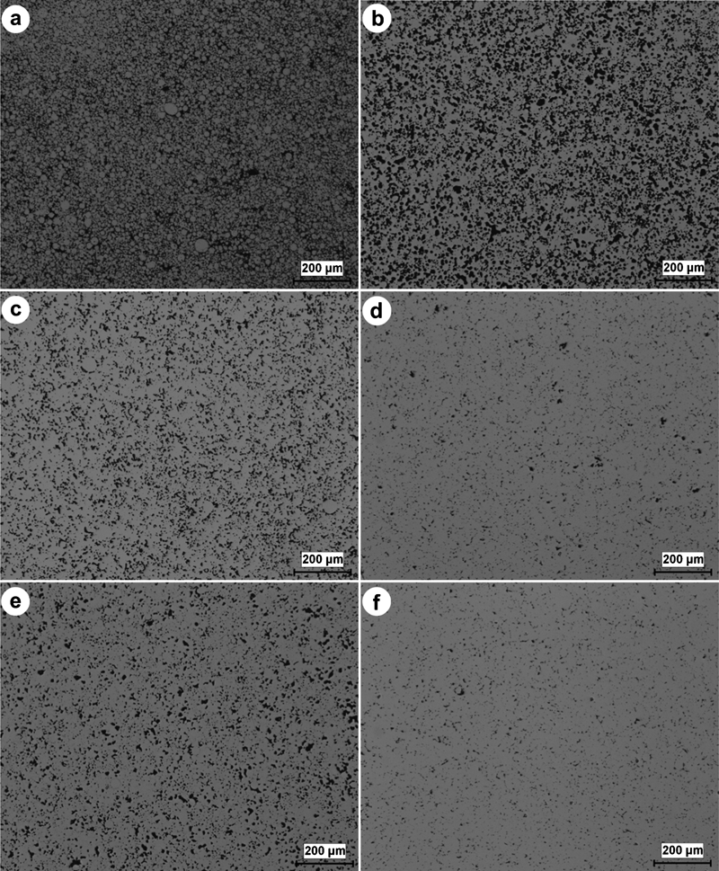
Optical micrographs of polished samples after sintering
In order to understand the grain structure of the sintered samples, optical images were taken after etching; these are shown in Fig. 8. It can be seen from these images that pores are often found between grains, and almost no pores are seen trapped in grains. The absence of pores in grains, which would otherwise create barriers to reach full density,21 suggests that higher density could be achieved for materials sintered for longer times. It is known that grain size increases with the increments of sintering temperature and time.21,23 When images are analysed, it is observed that the grain size grew with increasing sintering time. In the present study, the average grain size measured for the sample that has the highest density is 50 μm after sintering at 1330°C for 3 h.
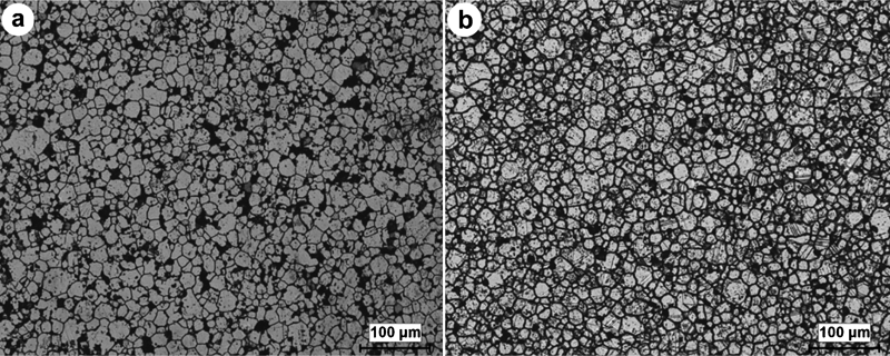
Optical micrographs of as etched samples
The hardness measurements for samples sintered for 1 and 3 h are shown in Fig. 9a and b respectively. It was observed from these graphs that, in parallel with an increase in density with increasing sintering temperature and time, the hardness also increased. Hardness measurements showed that the Vickers hardness value of the sample with the highest density, which was sintered at 1330°C for 3 h, is 349±10 HV0·1. In the study made by Nobrega et al. 20 using gas atomised powder, the hardness value reported was 228±14 HV10 N as a result of sintering at 1310°C for 3 h. The value obtained when using water atomised powder was reported to be 305±8 HV10 N. The difference was reported to be due to the high Cr, Co and Al contents of the water atomised powder.20
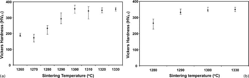
Hardness values obtained from sintered samples at different temperatures
Heat treatment studies were carried out on samples that were sintered at 1330°C for 3 h because these sintering parameters provided the highest density values. The samples were solution treated as indicated in standards18 and then aged at 705°C for varying times. In Fig. 10, microhardness values were measured from aged samples. Although not shown in the graphs, it was an interesting observation that the hardness of the sample increased after solution heat treatment. The hardness value of the solution treated sample was measured as 360±10 HV0·1. The highest increase in hardness occurred at aging periods (16 h) as indicated in standards for wrought Nimonic-90 materials. This value was measured as 378±20 HV0·1. The increase in hardness suggests the formation of carbide or intermetallic precipitates in the material. In the study performed by Nobrega et al. 20 using water atomised powder, hardness of 382±9 HV10 N is obtained as a result of aging treatment made after sintering at 1280°C for 3 h. In the previous research, the hardness of the material was reported as 364±8 HV10 N, which was produced under the same conditions without heat treatment.20 In this case, heat treatment provided only a 5% increase in hardness. In this study, the hardness value of the as sintered condition was increased by 8% after aging. In a study conducted by Gülsoy et al.,16 it was reported that the hardness value of the Nimonic-90 material sintered for 2 h at 1285°C as 30 HRC, which is approximately equal to 310 HV.
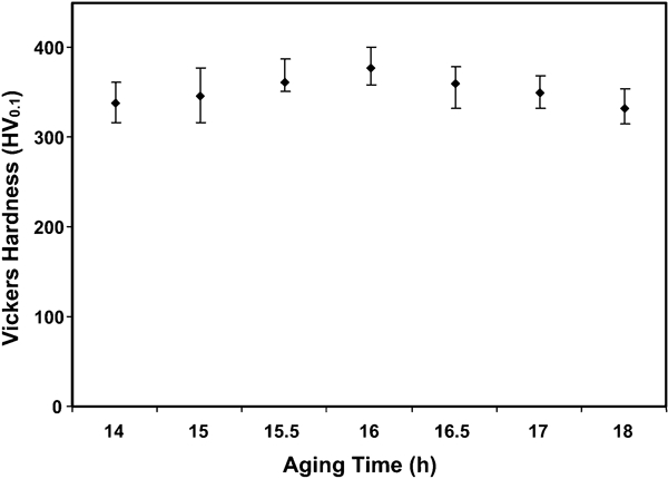
Hardness exchange depending on heat treatments performed for different periods at 705°C
After sintering and heat treatments, the SEM images taken from the microstructure of the samples produced by PIM are shown in Fig. 11. From these images, it was observed that in the grains of the austenitic matrix there is an abundance of annealing twins. After solution treatment, a number of precipitates were seen at the twins and grain boundaries; these are thought to be carbides. The increase in hardness resulting from solution operation is believed to be caused by these formations.
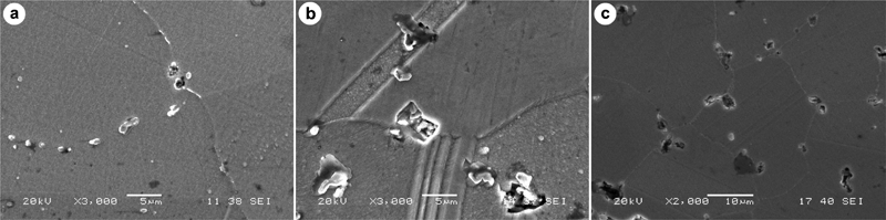
Image (SEM) of a sample sintered at 1330°C for 3 h, b solutionised sample and c aged sample
In order to understand the nature of the precipitates formed in the microstructure after the solution process, SEM elemental mapping analysis of the solutionised sample was performed, and the results are shown in Fig. 12. According to this elemental map analysis, C exhibits an accumulation in this grain boundary precipitate, indicating that this precipitate is a carbide. In the microstructure of nickel based superalloys, the carbide forming elements are Ti, Nb, Ta, Hf, Cr, Mo and W.24 When the map is analysed in the area of this precipitate, Al and Ti are also apparently associated with C. This would suggest that the carbide could be Al or Ti carbide. However, the phases that may occur in Ni based superalloys are explained in detail in the literature, and there is no evidence of Al carbide.24 In the context of nickel based and nickel–iron based superalloys, the MC type carbides are TiC, TaC and NbC.25 In the context of nickel based superalloys, Al does not create carbide; it can be said that the formation that was observed in the map analysis is TiC. The MC type carbides do not exhibit any definite orientation relationship with the austenite matrix. These carbides occur as discrete particles with coarse random cubic or script morphologies, distributed heterogeneously in transgranular as well as intergranular locations. The morphology of carbide precipitates in nickel based superalloys has an important bearing on the overall properties. Precipitation of carbide films as continuous grain boundary films can severely degrade the impact and rupture properties of the alloy by providing an easy fracture path. The formation of large and discrete particles at grain boundaries is beneficial since they effectively inhibit grain boundary sliding.25 However, because solution treatment is done with the aim of obtaining a supersaturated solid solution of elements before the aging operation, the formation of this kind of stable carbide precipitate and the consequent reduction in the amount of Ti available for γ′ phase formation are thought to be a negative development. Therefore, because of prior TiC precipitation, less γ′ phase was formed after aging due to the reduced availability of Ti, and consequently, the increase in hardness and strength was moderated.24 This situation is similar to the following statement stated in the literature: when a superalloy solutionised in an atmosphere has a carburising potential, the added carbon forms a stable carbide (TiC), thus removing titanium from solid solution and preventing normal precipitation hardening in the surface layers.24 The following description supports our idea as well: the formation of TCP phases involves the scavenging of strengthening elements from the alloy matrix, and it results in changes in volume fraction and stability of the strengthening intermetallic phases, thereby resulting in the weakening of the alloy.25,26
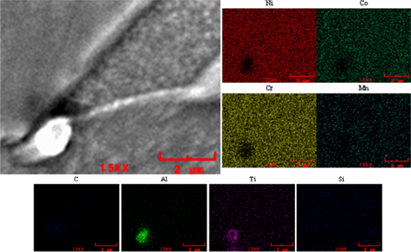
Map (EDS) images of solutionised sample
Figure 13 shows a schematic representation of the phases that may occur in the microstructure of nickel based superalloys.27 From this schematic image, it is seen that γ′ phase can be precipitated both at grain boundaries and in grains of austenitic matrix. γ′ precipitates can also form at surfaces of MC type carbides. From this point of view, it is thought that γ′ [Ni3(Al, Ti)] precipitates could be formed at the surfaces of MC carbides, which are observed in TiC form in the map image (Fig. 12). This may indeed be occurring around the TiC precipitate observed in map analysis and from Fig. 13, where high concentrations of Al and Ti are observed.
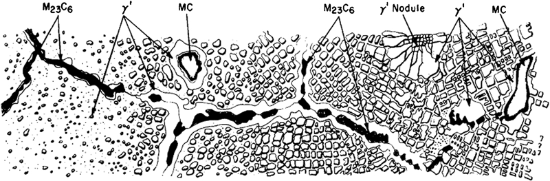
Schematic representation of phases that may occur in microstructure of nickel based superalloys26
Figure 14 shows the XRD patterns of the starting powder, the sintered samples at 1330°C for 3 h and the sample that was sintered under the same conditions and then subjected to heat treatment. The results of the XRD analyses show that nearly identical patterns were obtained from the prealloyed starting powder, sintered samples and aged samples. In all three cases, only the gamma (γ) peaks of the matrix can be obtained. Carbides and especially intermetallic precipitates, which are the purpose of the aging treatment, cannot be detected by XRD analysis due to their low concentrations. In a study conducted on a nickel based superalloy after aging treatment, even when sensitive XRD analysis was made using a 0·002 mm step length and a 12 s duration for every step, precipitate peaks could not be obtained.28,29 However, it was indicated that the changes observed in the XRD patterns of the gamma matrix could be used to determine indirectly the presence of precipitates.28
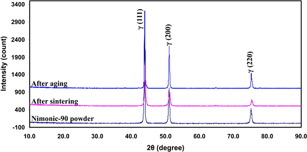
X-ray diffraction patterns of starting powder, sintered parts and aged parts
To determine the room temperature tensile strength and ductility values of Nimonic-90 materials produced by PIM, both sintered and aged samples were subjected to tensile tests. Figure 15 shows the tensile test curves (average of five tests) for sintered and aged samples. The yield and tensile strength of the material increased with aging treatment. The increase in hardness and strength values as a result of heat treatment suggests that intermetallic precipitates and carbides are formed in the material. In most precipitation hardenable nickel based superalloys, the main strengthening phase is γ′. The precipitation of γ′, Ni3(Al, Ti), in a high nickel matrix provides significant strengthening of the matrix. This unique intermetallic phase has a face centred cubic structure similar to that of the matrix and a lattice constant having 1% or less mismatch in the lattice constant with the γ matrix. Precipitation of γ′ from the supersaturated matrix yields an increase in strength. The volume percent of γ′ precipitated is also important because high temperature strength increases with the amount of the γ′ phase present. The amount of γ′ formed is a function of the content of the hardening alloy element(s). These include aluminium, titanium, niobium and tantalum, which are strong γ′ formers.30 Ti also forms MC type carbide, and this phase provides extra strengthening.2 However, as mentioned above, because a portion of Ti partitions to carbide, the amount of γ′, which contains Al and Ti, was reduced after aging, and therefore, it can be said that the increase in strength is moderated.
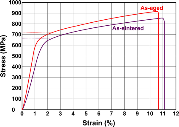
Average tensile curves of sintered and aged samples
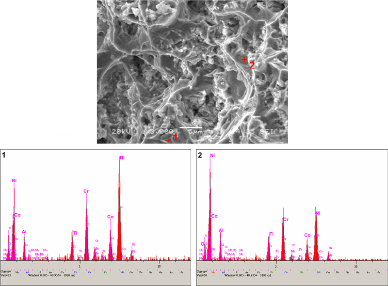
Tensile strength and ductility values obtained from tests on PIM parts are given in Table 3, together with properties of Nimonic-90 materials manufactured via cast or wrought routes. The strength of the materials produced by PIM is seen to be superior to that of cast parts. Wrought materials are seen to have higher strength due to the absence of pores seen in the PIM material. Nobrega et al. 20 in their study achieved an average of 785 MPa yield strength, 1144 MPa tensile strength and 22% elongation from samples produced using water atomised Nimonic-90 powders and sintered at 1280°C for 2 h. After heat treatment, the values are 906 MPa, 1249 MPa and 22% respectively.20 The lower strength values obtained in this study may be caused by the relatively low density of current material and the higher Al content in the water atomised Nimonic-90 powder used in the other study.
Tensile strength and elongation values of injection moulded Nimonic-90 samples
Control of carbon and oxygen content was the most important issue in producing the superalloys by PIM. It determined not only the mechanical properties but also the dimensional stability and corrosion properties. Table 3 shows the residual carbon content after heat treatment stages. The sintered and heat treated samples contained a larger amount of carbon than the starting powders. Residual carbon amounts could be found in the debinding stages. The lower levels of carbon in the PIM materials are the likely cause of both higher strength and ductility.21,23
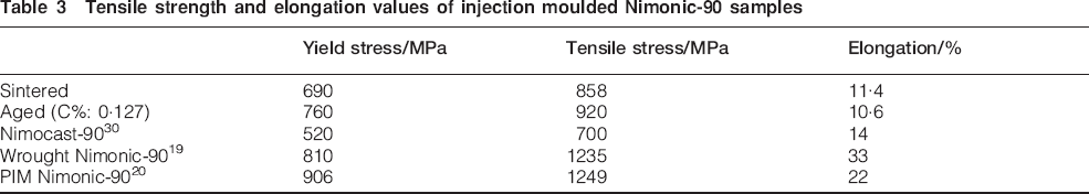
After tensile testing, the fracture surfaces of aged samples were examined; these are shown in Fig. 16. It is seen that fracture occurs primarily at intergranular locations, and other non-ductile failure behaviour is due to incomplete sintering and porosity. On the other hand, fully sintered regions exhibit ductile dimple fracture.
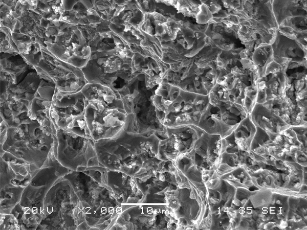
Image (SEM) of fracture surface of aged sample
The EDS analyses taken from fracture surfaces are shown in Fig. 17. Carbon was not observed at either location, suggesting that the debinding process is successful. Although there is no oxygen presence at point 1, there was a quantity of oxygen found at point 2. This situation could be caused by the aging treatment that was carried out in air. In nickel based superalloys, Ti is present in solid solution or as intermetallic (Ni3Ti) precipitates or TiC. In the same way, Al is available in solid solution or intermetallic phase (Ni3Al).30 Since there is no evidence of carbon or oxygen at point 1, this suggests that Ti and Al are in the form of intermetallic or solid solution at point 1. However, at point 2, Al could be present in part as Al2O3 and in solid solution and/or intermetallic Ni3Al.
Analyses (EDS) taken from fracture surface of aged tensile samples
Conclusions
In this study, components have been made by PIM from prealloyed Nimonic-90 superalloy powder with different sintering and heat treatment parameters. From these experimental studies, the following results were found.
The DSC analysis of the debinded samples of Nimonic-90 showed that melting starts at 1318°C and continues up to 1350°C. According to this result, it is thought that in the sintering processes that were carried out at 1320 and 1330°C, the super solidus liquid phase sintering mechanism will be active.
Density measurements on sintered parts show that depending on the sintering temperature and time increase, the density increases. The highest density was obtained when sintering at 1330°C for 3 h.
Optical images taken after etching show that for the same sintering temperature, increasing sintering time results in grain growth. It is observed that a grain size of ∼50 μm is achieved in samples that display the highest density, obtained at 1330°C.
The hardness measurements after sintering show that hardness increases in parallel with increasing density. The maximum hardness was obtained as a result of an aging treatment at 705°C for 16 h. The hardness of samples sintered at 1330°C for 3 h is 349±10 HV0·1, and this value increases to 378±20 HV0·1 after aging.
The XRD peaks characteristic of the gamma matrix were measured for the starting powder, sintered sample and aged material. Changes in these peak areas and amplitudes are indirect indicators of changes caused by changes in heat treatment of material.
The yield stress, ultimate tensile stress and elongation values from sintered samples was respectively 690 MPa, 858 MPa and 11·4%. The values after aging treatment are 760 MPa, 920 MPa and 10·6% respectively. In both cases, the strengths of injection moulded samples are much higher than Nimonic-90 materials produced by casting.
Footnotes
Acknowledgements
The authors are grateful to TUBITAK-MAM, Material Research Institute, Marmara University (Project No. FEN-C-YLP-071211-0311), Sakarya University (Project No. 2012-50-02-006) and Sandvik Osprey Ltd for their financial support and the provision of laboratory facilities.