
Abstract
Low alloy sintered steels with an optimised content of alloying elements require the use of promising candidates such as Mn and Si, which can provide improved properties with minimum contents at a lower and less volatile price. The introduction of these alloying elements in the form of a master alloy powder prevents, to some extent, the oxidation and allows a proper ‘tailoring’ of its composition to accomplish particular goals. In this sense, low melting point alloys are especially interesting since they provide the formation of a liquid phase that enhances sintering and promotes the homogeneous distribution of alloying elements within the compact. In this work, the product developing process of master alloys containing Fe–Mn–Si is described from the theoretical design to the sintering performance. The effects of the liquid phase (produced by the added master alloys) are studied by differential thermal analysis and dilatometry. Moreover, to depict the behaviour of the liquid phase during heating, interrupted sintering experiments under high cooling rates were carried out. The results reported allow us to conclude that diffusion of carbon seems to be beneficial for lowering the melting temperature of the alloying particles, and the fact that the master alloys studied can dissolve part of the iron base particles has been shown to be beneficial for wetting.
Keywords
Introduction
Lean steels can be defined as low alloyed steels with a minimised content of alloying elements (<3 wt-% in the powder metallurgy context), which maintain or even improve the level of properties in conventional sintered steels. Although the term ‘lean steels’ has been recently coined, this particular goal has been pursued since the early 1970s, when manganese–chromium–molybdenum and manganese–vanadium–molybdenum master alloys were first introduced in the market.1– 5 At that time, it was already known that improvement of the properties at a lower alloying cost should come by the introduction of elements such as Cr, Mn or Si, which had been used for many years in conventional wrought steels, but had limited applications in powder metallurgy due to their high affinity for oxygen. These researches posed the possibility of avoiding oxidation using the ‘master alloy concept’ since the introduction of elements with a high oxygen affinity in the form of a carbon containing master alloy could reduce its chemical activity and therefore protect them against oxidation. Moreover, the melting of these master alloy particles during the sintering process proved to enhance sintering and promote the homogeneous distribution of the alloying elements.
During the last decades, and fomented by the increasing interest in manganese sintered steels, successful master alloy systems containing manganese have reported impressive properties at a very low alloying cost.6– 8 Besides manganese, silicon is also a very promising candidate that provides an excellent strengthening effect in sintered steels. Furthermore, by combining simultaneously Mn and Si, sintered steels with excellent properties in the as sintered stage were obtained in the 1980s by Klein et al., who reported small dimensional changes during sintering combined with a remarkably high strength.9– 12 However, Mn–Si sintered steels have never reached the market.
In the attempt of reopening the research on Fe–Mn–Si sintered steels, the master alloy route seems to be a promising option. It helps to prevent the oxidation, maintains the compressibility of the base powder and also allows a certain degree of flexibility in composition when compared to prealloyed powders. However, in many cases, the problems are related with the difficulty of dissolving completely the master alloy particles and distributing properly the alloying elements. In the last years, the development of software tools allows the design of master alloy compositions with a low melting point.13,14 This ensures the formation of a liquid phase during the sintering process, which facilitates the distribution of alloying elements and also enhances sintering.
In this work, the systems Fe–Mn–Si and Fe–Mn–Si–C have been assessed in order to find low melting point compositions that ensure the formation of a liquid phase at common sintering temperatures. However, the fact that the master alloy powders are present in a mix where diffusion processes take place long before the formation of the liquid phase raises some questions about the possible shifting in the melting temperature of the master alloy particles. The behaviour of the liquid phase formed is clearly described here using wetting experiments, differential thermal analyses (DTAs), dilatometry and interrupted sintering experiments.
Materials and experimental procedure
Thermodynamic calculations
Thermodynamic calculations were performed with ThermoCalc software15 using the database SSOL4. The lowest liquidus temperatures were calculated in the ternary system Fe–Mn–Si and the quaternary system Fe–Mn–Si–C through the projections of the liquidus univariant lines. The liquidus lines of both phase diagrams were calculated over the whole range of compositions available in the database.
In order to calculate the liquidus univariant lines of these systems, a starting point is required for calculating and storing an initial equilibrium. The calculation of this initial equilibrium in an n component system requires n+2 defined variables. The variables defined were pressure (1 bar), size of the system (1 mol), temperature and n−1 compositions. The temperature and n−1 compositions were selected to be close to an invariant point of a lower order system, for instance, in the calculation of the quaternary system Fe–Mn–Si–C, the ternary eutectic point found in the system Fe–Mn–Si was used. After defining this initial equilibrium, ThermoCalc can scan along up to five variables, such as, for instance, temperature and four composition axes. However, from these five variables, at least three of them must be potentials; therefore, no more than two chemical composition variables are allowed. This was solved by introducing two chemical compositions and substituting the chemical composition of the remaining elements by its chemical potential or activity.14
Master alloy compositions designed by ThermoCalc calculations were prepared as ingots for wetting experiments and as gas atomised powder for thermal analyses.
Wetting experiments
The materials used in the wetting experiments are summarised in Table 1. The master alloy used as liquid phase promoter was prepared from high purity Fe, Mn and Si by melting in an induction furnace under He atmosphere in order to obtain a dense specimen (of ∼2 g), which can provide a homogeneous melting. For the wetting experiments, samples of ∼30 mg were cut from the ingot.
Substrate and master alloys used for wetting experiments
Wetting experiments were carried out in a DSAHT furnace equipped with an observation window and a recording system, designed by the company Krüss. The characteristics and configuration of this equipment are described elsewhere.16,17 Initially, the oxygen level in the furnace chamber was decreased using a vacuum system and keeping the pressure stable at 10−2 mbar. The experiments were run under Ar atmosphere at a normal pressure and a dew point of ∼−19°C controlled in the ‘gas outlet’ exit. The pair drop substrate was heated up to 800°C at a heating rate of 20° min−1. In the temperature range from 800 to 1200°C the heating rate was decreased to 5° min−1, and the wetting process was filmed at rate of 2 fps (‘frames per second’).
The software ‘Drop Shape Analysis’ was used for measuring the contact angle. Different measurement methods were chosen depending on the drop features. In the calculations, the time origin corresponds to complete melting of the droplet.
Thermal analyses
The materials employed in thermal analyses are gathered in Table 2. Master alloy powders were obtained by gas atomising in nitrogen in a lab scale atomiser from the company Atomising System Ltd (Sheffield, UK).
Materials used in thermal analyses studies
Thermal analyses consist on DTAs and dilatometry experiments. Table 3 shows the equipments used and the conditions applied for the different experiments.
Thermal analyses: equipments used and conditions applied
The melting temperatures of the two master alloy powders were calculated by DTA analyses on loose powder with or without carbon additions. When present, carbon was added as graphite in an amount of 0·6 wt-%.
Master alloy Fe–Mn–Si–C was selected for further thermal analyses. Melting of the master alloy particles during the sintering cycle of the steel was investigated by DTA experiments on green steel compacts containing base powder, master alloy powder and 0·6 wt-% graphite, pressed at 600 MPa. Two different base powders were used in these studies: plain iron and prealloyed iron powder. For each base powder, three scenarios are considered: no master alloy addition, 4 wt-% master alloy and 20 wt-% master alloy. This latter composition (20 wt-% master alloy) was included with the aim of exaggerating the effects of the liquid phase formation.
Dilatometry experiments were carried out on green samples with plain iron base powder, 4 wt-% master alloy and 0·6 wt-% graphite pressed at 600 MPa. The different blends were mixed for 30 min in a turbula mixer.
The dimensional changes occurring due to the formation of the liquid phase were monitored through dilatometry experiments, which allowed the identification of relevant temperatures in the sintering cycle. Afterwards, interrupted sintering experiments were carried out in a quenching dilatometer at the temperatures previously defined by the former dilatometry experiments. In step sintering runs, the samples were held for 2 min at the target temperatures and rapidly cooled in order to freeze any liquid phase formed. After the experiments, the samples were examined by optical microscopy.
Results and discussion
Design of low melting point alloys
Fe–Mn–Si system
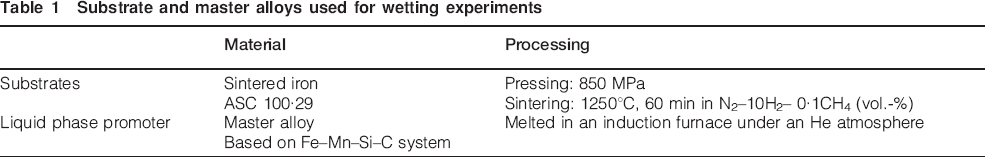
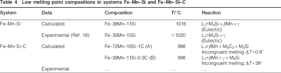
In the phase diagram of a n component system, eutectic points are determined by the intersection of n univariant lines, where all n lines lie above the intersection point.13 The projections of the univariant lines in the phase diagram of the system Fe–Mn–Si were calculated with the software ThermoCalc and are represented in Fig. 1. A eutectic point is predicted from Fig. 1 at 1016°C with a composition of Fe–38Mn–11Si (wt-%). A similar eutectic reaction is defined in the literature available at the same temperature and only at slightly different composition of Fe–30Mn–15Si (wt-%) (Table 4). The resemblance between both ThermoCalc data and the data provided by the literature indicates that an alloy with a composition close to the point predicted by ThermoCalc is likely to melt well below the common sintering temperatures (1120–1250°C).
System Fe–Mn–Si. Projection of univariant lines of liquidus surfaces onto (left) composition versus composition plane and (right) temperature versus composition plane. Arrows in composition versus composition plane indicate direction of decreasing temperature
Low melting point compositions in systems Fe–Mn–Si and Fe–Mn–Si–C
Fe–Mn–Si–C system
The projections of the univariant lines in the system Fe–Mn–Si–C did not provide any intersection point of four univariant lines; therefore, no eutectic points can be reported for this system (Fig. 2). Instead, two compositions that presented low liquidus temperatures (points A and B) were considered interesting (Table 4). The liquidus temperatures in both points are similar, and the main difference was found on the melting window (degrees between liquidus and solidus temperatures), which is <1° for composition A and ∼40°C for B.
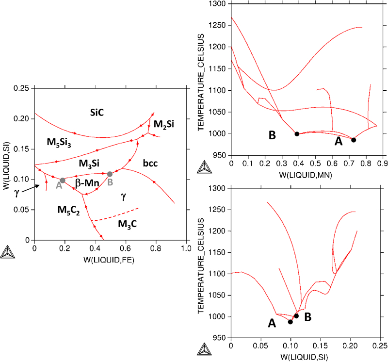
System Fe–Mn–Si–C. Projection of univariant lines on liquidus surfaces onto (left) composition versus composition plane and (right) temperature versus composition plane. Arrows in composition versus composition plane indicate direction of decreasing temperature
After these calculations, two compositions were selected for further studies: one system Fe–Mn–Si with a composition close to the calculated eutectic, and one system Fe–Mn–Si–C with a composition similar to point B. Point B was selected for having a composition very similar to that of the system Fe–Mn–Si but including carbon.
Wetting experiments
The wettability of the master alloy Fe–Mn–Si–C on plain iron substrates under N2–10H2 atmosphere has been reported in previous studies and compared with the wettability of Cu on the same type of substrates but under Ar atmosphere.16,17
Reducing atmospheres favour wetting of plain iron substrates, providing wetting angles of ∼20° for the Fe–Mn–Si–C master alloy17 and close to 0° for liquid Cu.19 However, the wetting behaviour of liquid copper is radically different when the experiments are performed under inert atmosphere, where the wetting angle measured was ∼70°.17 Owing to the important differences found in the wetting behaviour of Cu when the atmosphere was modified, wetting angle experiments have been carried out in this study using the same Fe–Mn–Si–C master alloy as in Ref. 17 but under Ar atmosphere.
An initial non-wetting behaviour is registered for the liquid master alloy on the iron substrate under Ar atmosphere (Fig. 3) and is due to the presence of an unreduced oxide layer on the surface of the iron substrate. With an Ar atmosphere and an iron substrate, which does not contain any carbon, there are no reducing agents available for removing the oxides. This same effect has been reported for liquid Cu19 under Ar atmosphere, where it was shown how wetting can be considerably improved by admixing carbon to the iron substrates, pointing out the important role of the reducing agents.19
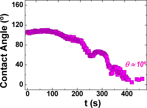
Evolution of contact angle after drop formation under Ar atmosphere. Substrate: plain iron, drop: master alloy Fe–Mn–Si–C
A few minutes (≈5 min) after drop formation, there is a decrease in the contact angle (Fig. 3) that evolves and reaches very low values (<10°). This evolution of the wetting angle is promoted by the dissolution of the substrate.
The dissolutive behaviour of these master alloys and its effects on wetting were elaborately depicted in Ref. 17 for experiments performed in reducing atmosphere. The studies presented here show how this dissolutive phenomenon could be possible even in the presence of unreduced iron oxides in the surface of the iron substrate. This is most likely due to the high oxygen affinity of the elements present in the liquid master alloy, which can promote oxygen transfer from the iron oxide. Reduction in this iron oxide layer allows dissolution of the substrate and further evolution of the wetting angle.
The conditions used for the wetting experiments performed here represent the worst case scenario where no reducing agents are available. The fact that the master alloy can wet the iron substrate even under such unfavourable conditions reveals one of the benefits of using a Fe–Mn–Si–C master alloy with a dissolutive behaviour.
Liquid phase formation during sintering
During the sintering cycle and due to the promoted diffusion of elements at high temperatures, there might be a change in the master alloy composition that affects its melting behaviour. In this sense, the most important influence is that of carbon, which presents the highest diffusion rate in iron.
The melting of the master alloy powders with and without graphite was studied through DTA experiments (Fig. 4). According to the DTA curves, the liquid phase is formed at ∼1135°C in the Fe–Mn–Si master alloy, while in the system with carbon (Fe–Mn–Si–C) is ∼1072°C. When graphite is admixed with both master alloys, the melting behaviour in the Fe–Mn–Si alloy is considerably different, while that of Fe–Mn–Si–C alloy remains almost unchanged. In this latter case, the presence of carbon on the initial composition of the master alloy hinders the diffusion of this element in the master alloy particle, and there are no changes on its melting temperatures. In case of the Fe–Mn–Si system, the diffusion of carbon leads to the formation of a liquid phase at lower temperatures. Moreover, the temperatures of liquid phase formation are found to be similar to those obtained with the Fe–Mn–Si–C master alloy. These results indicate that, for the Fe–Mn–Si system studied, the addition of small amounts of carbon (<1 wt-%) either in the initial master alloy composition or by the addition of graphite is beneficial since it helps to reduce the melting point and therefore ensures the formation of a liquid phase at the sintering temperature.
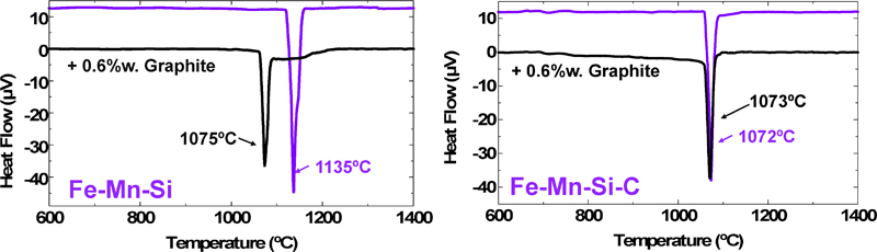
Differential thermal analysis experiments for two different master alloy atomised powders [(left) Fe–Mn–Si, (right) Fe–Mn–Si–C] with and without additions of graphite
The Fe–Mn–Si–C master alloy was selected for thermal studies on green steel compacts since the presence of carbon in the master alloy composition might help to prevent the oxidation during the heating stage. Figure 5 shows the DTA curve of steels containing either plain iron (left) or prealloyed iron (right) as base power and increasing amounts of master alloy.
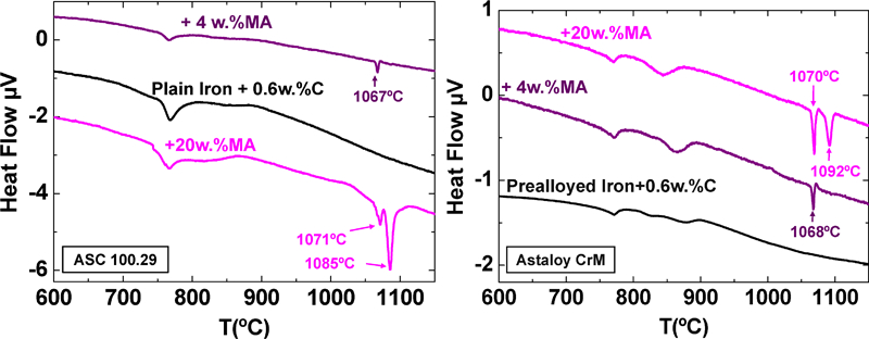
Differential thermal analysis experiments performed with two different base powders [(left) plain iron, (right) Cr prealloyed iron] adding increasing amounts of master alloy
The results are similar for both base powders, which indicate that the chemical composition of the base powder is not affecting the melting behaviour of the master alloy. If no master alloy is added, only the α→γ transition is observed in this range of temperature. Adding 4 wt-% master alloy, an additional endothermic peak is found at the melting temperature of the master alloy. When the amount of master alloy is increased to 20 wt-%, two endothermic peaks are observed. The first endothermic transformation occurs at the melting temperature of the master alloy, and the second one at ∼15–20° above. The emergence of this second endothermic transformation is linked to the presence of a higher amount of liquid in the mix and is very likely associated with the dissolution of the base powder, which is emphasised when the amount of dissolving liquid increases.
The formation of a liquid phase usually has an influence on the dimensional changes that the sample undergoes during the sintering cycle. The dilatometry curve obtained for green compacts containing 4 wt-% master alloy and plain iron as a base powder, sintered under Ar atmosphere, is presented in Fig. 6. An abrupt change in the slope of the dilatometry curve is taking place during the heating cycle and is associated with the liquid phase formation. This change in the slope is clearly seen with the derivative of the dilatometry curve and is registered at temperatures between 1110 and 1175°C.
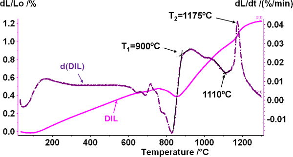
Dilatometry curve and derivative
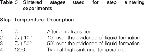
In order to understand the phenomena taking place during the liquid phase formation, step sintering experiments were carried out by heating at defined temperatures and cooling rapidly in order to freeze any liquid phase formed. The temperatures were selected based on the dilatometry curve in Fig. 6 and are defined in Table 5.
Sintered stages used for step sintering experiments
The dilatometry curves obtained after the step sintering experiments are represented in Fig. 7. From these curves, it is evident that the sample in step 1 was cooled just after α→γ transformation and in steps 2 and 3 close after the change in the slope.
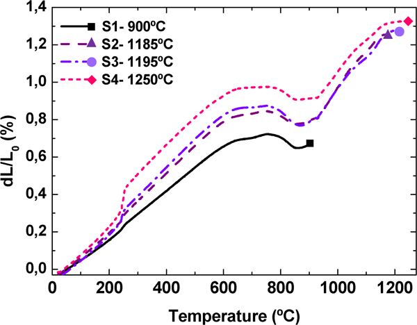
Dilatometry curves for four-step sintering experiments. Heating rate: 10° min−1
The micrographs of the samples obtained after step sintering experiments are shown in Fig. 8. The image of step 1 evidences that carbon, which was introduced as graphite, is completely distributed within the mix long before melting of the master alloy. Stages 2 and 3 show the evolution of the melting process. The microstructures observed in stages 2, 3 and 4 are fully martensitic; however, in order to avoid overetching of the areas containing master alloy, short etching times were used (<2 s). Owing to these short etching periods, only the martensitic microstructure of the areas surrounding the master alloy particles is revealed. It is clearly seen how even before the end of the melting process, the liquid available has already started to dissolve the surface of the iron base powder. An increase in the sintering temperature is helping to complete the melting of the master alloy particles and is always accompanied by dissolution of the surrounding base powder. At high sintering temperatures, the master alloy particles melted completely, and brown halos are observed around the secondary porosity left probably due to the higher concentration in alloying elements. The interrupted sintering experiments confirm the efficiency of the liquid phase formed in promoting the introduction of alloying elements in the base powder particles, which is somehow helped by the dissolution phenomena.
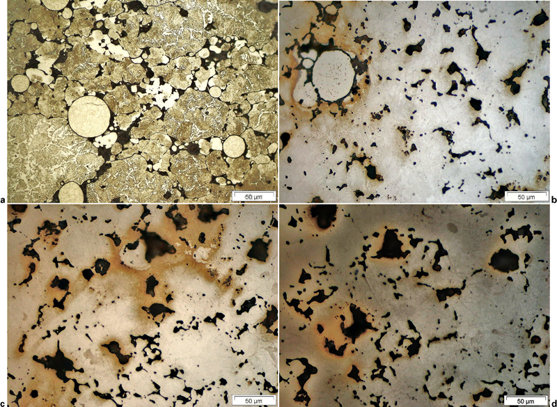
Micrograph of samples after step sintering etched with 2% nital. Heating rate: 10° min−1
Conclusions
Master alloy compositions that ensure the formation of a liquid phase at temperatures lower than the common sintering temperatures have been found for the systems Fe–Mn–Si and Fe–Mn–Si–C using thermodynamic calculations performed with the software ThermoCalc.
The melting point of the master alloy seems to be influenced by the diffusion of carbon in master alloy particles, but only when there is no carbon already present in the master alloy composition. For the compositions studied here, diffusion of carbon seems to be beneficial for lowering the melting temperature of the alloying particles.
The fact that the master alloys studied present elements with a high affinity for oxygen might help to reduce the iron oxide layer present in the surface of the iron substrate, which can lead to the dissolution of the substrate and wetting improvement. This could be especially interesting when the local conditions do not allow complete reduction in the iron oxides, since the liquid master alloy might be able to eliminate the oxide barriers and therefore improve wetting.
The dissolutive behaviour of these master alloys combined with an iron base powder has been proved both by DTA experiments and by interrupted sintering experiments and is thought to be advantageous in order to improve the introduction of alloying elements in the iron base particles.
Footnotes
Acknowledgements
The authors wish to thank C. Gierl and H. Danninger from the Technical University of Vienna, Austria, for their assistance in dilatometry analyses. The financial support provided by Höganäs AB Sweden, by the MICINN Spain through project no. ENE2009-13766-C04-03 and by CAM Spain through project no. S2009/MAT-1585 is gratefully acknowledged.
This paper is part of a special issue on ‘Euromat 2011: powder synthesis and processing for controlled microstructure’