
Abstract
Monosize alloy droplets are produced by controlled capillary jet break-up, a droplet generating process, also used in ink jet printing technology. With Rayleigh instability controlled through the decoupled process parameters of jet diameter, mass flowrate and perturbation frequency, monosize droplets of desired diameter can be generated at high rates with essentially full yield. The uniform size of droplets assures nearly identical solidification paths for all the droplets generated under fixed process conditions. This permits precise prediction of the motion and thermal and solidification behaviours of the droplets through rigorous process and metallurgical modelling, which is applicable to industrial thermal spray processes as well. Uniform droplets can be in-flight solidified or deposited on a substrate to produce various forms of materials with novel rapid solidification microstructures. Areas of industrial applications are discussed.
Keywords
Introduction
Solidification processing normally determines the starting microstructure for subsequent manufacturing steps, e.g. deformation and thermal processing, machining, joining and surface treatment. Therefore, the process of solidification must be optimised not only for the final properties required for the product but also for the manufacturing steps that follow. Unlike conventional casting, which inevitably produces materials with a coarse dendritic microstructure, microingot casting processes, such as gas atomisation and plasma spraying, produce particulates with rapidly solidified microstructures with reduced chemical segregation.
However, these conventional microingot processes by no means produce materials with truly uniform microstructures, owing primarily to the intrinsic limitation arising from the non-uniform size distributions of alloy droplets in a conventional molten spray. As a result, gas atomised powders are often sieved to remove particles with undesirable sizes before shipping. Empirical correlations between the particle cooling rate and a characteristic scale of the solidification microstructure, e.g. the secondary dendrite arm spacing,1 provide a basis for such size based classification.
While size based classification of atomised powders has been an effective commercial practice, it is well known that the rapid solidification microstructures that evolve in alloy droplets really depend on the path along which solidification takes place, rather than the droplet cooling rate alone. This is because droplets of the same size may still experience different degrees of undercooling, depending on the potency and population of nucleation catalysts in the droplet2 as well as on the cooling rate. Moreover, the cooling rate, which directly translates into the rate of heat removal, affects not only the undercooling but also the duration of the post-recalescence solidification that determines the characteristic scale and morphology of the final microstructure,3,4 Thus, the exact solidification path depends on both the processing conditions and the material being processed in a complex, coupled way.
Conventional molten sprays are also deposited on a substrate, as in spray forming and plasma spraying, to produce bulk materials and coatings by the incremental solidification of deposited droplets. While deposited alloys so produced are largely free of coarse, macroscopically segregated structures, they are never truly uniform structurally nor have full density, due to the non-uniform size distribution of the droplets in conventional sprays that cause non-uniform droplet motion and solidification. Consequently, spray deposited materials normally require secondary processing, such as thermomechanical processing,5 or else can be used only as coatings.6
The above limitations of conventional molten sprays are largely removed in the uniform droplet spray (UDS) process7 where droplets are all identical in size, motion and the way they solidify. The following sections describe the principles of the UDS process and a model developed for the prediction of the motion, nucleation kinetics and solidification of the droplets, and discuss current and potential applications of the UDS process.
Uniform droplet sprays
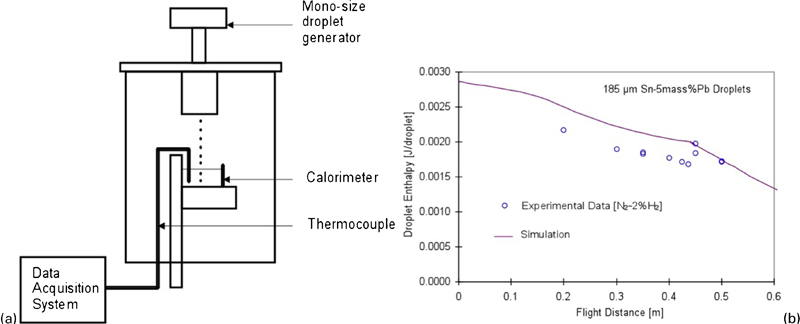
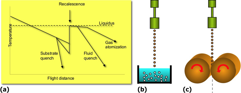
The UDS process, as depicted schematically in Fig. 1, exploits the Rayleigh instability8 on a liquid jet, as in ink jet printing, to generate monosize alloy droplets by the break-up of molten jet at a rate controlled through regulated vibration imposed on the jet.7,9 The volume of a droplet in the UDS equals the volume flowrate Vj divided by the vibration frequency fv and is controlled through three decoupled parameters: the diameter of the orifice through which the molten jet is ejected, the ejection gas pressure that controls the initial jet velocity and the frequency of the imposed vibration.9 For a given jet diameter dj, the perturbations that grow fastest have a wavelength of about 4·5dj.8,9 Thus, the jet breaks up into monosize droplets of volume Vj/fv when the three process parameters are adjusted to perturb the jet with a wavelength of about 4·5dj. The droplets may be charged electrically as they leave the parent jet using a charging plate just below the orifice to prevent the molten droplets from merging during their flight.
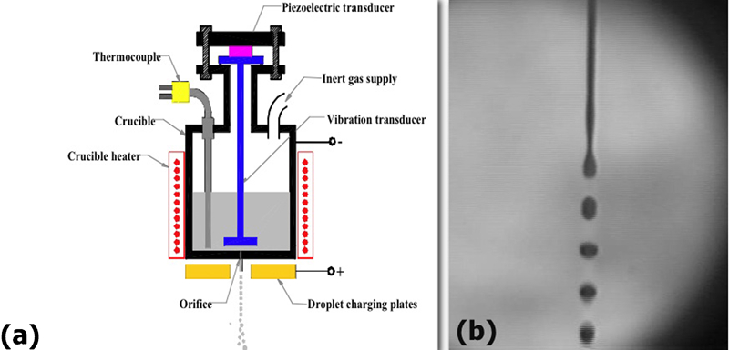
a schematic of UDS process and b snapshot of uniform jet break-up
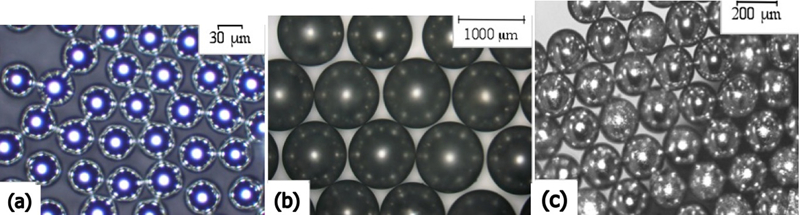
Metals and alloys that have been sprayed by the UDS process include Sn and Sn base solder alloys, Al alloys, Mg alloys, Cu, Co alloys, Si and Fe alloys.9– 20 Figure 2 shows monosize balls of an Sn base solder alloy,10 a Mg alloy (AZ91D)11 and an Fe–4 mass-%B alloy12 produced by allowing the droplets to solidify in flight. Work conducted to date suggests that droplets produced under a set of conditions have a diameter within ±3% of the target diameter and that production of monosize droplets as small as 30 μm in diameter is possible.
In-flight solidification of alloy droplets
The solidification of alloy droplets has been an important topic in materials research as it provides an effective route for the production of alloy powders with rapid solidification effects, namely, grain/particle size refinement, extended solid solubility, the formation of non-equilibrium phases and the retention of metastable phases and structure.21 Most of the fundamental studies of alloy droplet solidification conducted to date have focused on the solidification of stationary droplets. Techniques developed and successfully employed in these studies are represented by the hot stage droplet dispersion techniques developed by Turnbull et al.,22– 24 the droplet emulsification methods explored by Turnbull25 and developed by Perepezko and co-workers26– 28 and Flemings and co-workers29 and the levitation melting techniques.30– 32 The solidification of moving droplets has also been investigated by drop tower methods,33,34 although the latter methods apply only to relatively large drops, typically a few millimetres in diameter, undergoing free fall.
More recently, the solidification of smaller travelling droplets (<1 mm in diameter) has been studied using monosize droplets generated by the UDS process.12,19 The uniformly sized droplets of a UDS cool and solidify along an essentially identical path, thus enabling droplet based solidification processing at the highest levels of microstructure control in the solidified material. Taking full advantage of the uniform droplet solidification, however, requires thorough characterisation and control of the solidification path of the droplets. The solidification path can be defined in four stages, namely, the initial liquid cooling, nucleation and recalescence, the post-recalescence solidification and the final solid cooling. The most critical information required to control the droplet solidification path is the temperature at which nucleation takes place in the droplet. The droplet nucleation temperature, for a nominal alloy composition, depends on the potency and population of the nucleation catalysts in the droplet, as well as on the droplet cooling rate, in a complex way2 and, as such, cannot be uniquely predicted. The subsequent rapid crystallisation during recalescence, which produces much of the useful rapid solidification effects, is driven primarily by the large chemical driving force across the solidification front and hence depends on the undercooling. The plateau stage after recalescence then follows, completing the droplet solidification at the rate limited by the heat removal from the droplet. The following describes the scheme of modelling and experimental procedure developed for the characterisation of the in-flight solidification of UDS droplets.
Motion and thermal state
Since the droplets of a UDS all have the same diameter, their motion, cooling and solidification are given by9,35,36
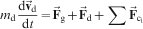
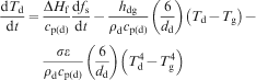
 , ρd, dd, Td and σ are respectively the mass, velocity, density, diameter, temperature and Steffan–Boltzmann constant of the droplets; Tg is the temperature of the gas; ΔHf, cp(d), fs and hdg are the latent heat of fusion, the specific heat, the fraction solidified and the convective heat transfer coefficient of the droplets respectively;
 ,
,
 and
and
 are the gravitational, aerodynamic drag and coulombic forces acting on the droplets respectively; and t is time. Equations (1) and (2) are coupled through the heat transfer coefficient, which depends on the relative velocity of the droplet and the gas.37
Nucleation temperature
The temperature at which UDS droplets nucleate depends on the potency and population of the nucleation catalysts present in the droplets. Therefore, it varies even for alloys of the same nominal composition, as well as for different sizes and cooling conditions. The nucleation temperature of UDS droplets can be determined by three experimental methods, namely, calorimetry,19,38 splat quenching12 and three-dimensional (3D) metallography.12
In the calorimetric method, the droplets are quenched in the fluid (oil) of a calorimeter to determine the heat transfer from the droplets to the calorimeter (Fig. 3a). This is repeated at various heights to determine the amount of heat transfer as a function of the distance travelled from the orifice or the flight distance. Figure 3b shows data so obtained for 185 μm Sn–5 wt-%Pb droplets,19 which also shows values for droplet enthalpy calculated with equations (1) and (2). The data points parallel the simulated values and decrease monotonically up to ∼0·46 m, but the experimental values fall short of the theoretical predictions consistently by 0·0003 J/droplet. This discrepancy at flight distances below 0·46 m is attributed to incomplete droplet to calorimeter heat transfer due to the formation of supersaturated Sn–Pb solid solution in the droplets, which happens when droplets are quenched in the molten state.19 Above 0·46 m, the data and the simulation agreed because the droplets entered the calorimeter fluid after nucleation and recalescence had taken place, giving up most of their enthalpy to the calorimeter. The sharp increase in experimental values at 0·46 m attests that nucleation occurred in most of the droplets over a very narrow flight distance, producing nearly identical solidification paths for the majority of the droplets. Similar data can be obtained with splats of UDS droplets quenched on substrates at various heights by offline differential scanning calorimetry.
Calorimetric determination of nucleation distance19
Quenched splats also permit determination of the nucleation distance more directly from their morphology. Figure 4 shows the longitudinal cross-sections of splats of 450 μm copper droplets quenched at 0·20 and 0·22 m from the orifice using a rotating quencher blade assembly that sheared the droplets into elongated splats.39 The thin, elongated splat collected at 0·20 m and the dome shaped splat collected at 0·22 m suggest that the nucleation of the 450 μm copper droplets took place at ∼0·21 m. A more exact value of nucleation distance, if required, can be calculated by cross-validating the splat quenching data with the volume fraction solidified during recalescence fs, which is related to the droplet undercooling via ΔT = [ΔHf/cp(d)]fs. The value of fs can be determined by 3D metallography.12
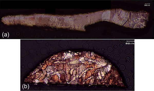
Top views and cross-sections of splats of 450 μm copper droplets quenched at a 0·20 m and b 0·22 m from orifice39
The nucleation distance determined by the above methods is then converted to the nucleation temperature TN with equation (2) where dfs/dt = 0.
Prediction of nucleation kinetics
The nucleation data obtained by the above methods can be ‘processed’ to extract information that permits predicting the nucleation kinetics of droplets of the alloy of concern for any diameter and cooling condition. For this purpose, Dong et al.,40 Wu and Ando41 and Li et al.
42 have developed droplet nucleation kinetic models that predict the nucleation temperature of a continuously cooling alloy droplet based on the classical nucleation theory. These models assume that nucleation in a continuously cooling droplet takes place when the incubation time for nucleation is used up cumulatively during the cooling so that43
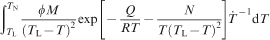
 , Q and R are the volume or surface of the droplet where nucleation can take place, the liquidus temperature of the alloy, the instantaneous cooling rate, the activation energy of liquid diffusion and the gas constant respectively, and M and N are material specific constants that account for the potency and density of the heterogeneous nucleation catalysts present in the droplet.
Equation (3) requires that the values of constants M and N be known for the alloy of concern. This is achieved by applying nucleation data (TN and
 ) from UDS experiments to equation (3) and by solving the resulting equations for M and N. Two sets of experimental data are required for internal nucleation, and four sets for oxidation catalysed surface nucleation.40–
42,44
) from UDS experiments to equation (3) and by solving the resulting equations for M and N. Two sets of experimental data are required for internal nucleation, and four sets for oxidation catalysed surface nucleation.40–
42,44
Applications
Powder classification
Once the values of the material specific constants are determined for the alloy of concern, equation (3) can predict the nucleation temperature of a droplet of the alloy of concern for any size and cooling schedule.41,45 Figure 5 shows the nucleation kinetics of droplets of an Sn–5 mass-%Pb alloy produced by gas atomisation in the form of continuous cooling transformation (CCT) curves for both internal and surface nucleation.45 The actual cooling rate of a gas atomised droplet, which depends not only on the diameter but also on the atomising gas and the gas dynamics, can be calculated with a model for gas atomisation, such as the one given by Liu et al. 46 Such CCT diagrams permit classifying atomised powders truly on the basis of solidification microstructure, instead of relying on conventional size based classification.
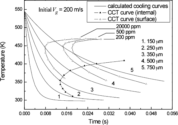
Continuous cooling transformation diagram for internal and surface heterogeneous nucleation of gas atomised Sn–5 mass-%Pb droplets45
Advanced droplet based materials processing
With the ability to predict and control the in-flight solidification of droplets, the UDS process can be exploited as a unique means for advanced droplet based materials processing in two important areas: particulate production and droplet deposition.
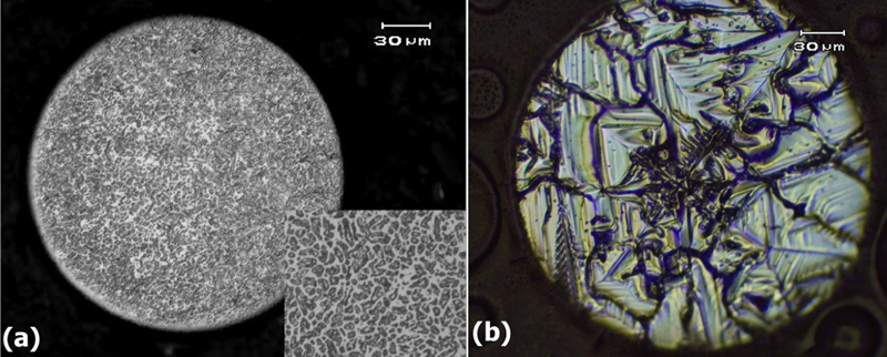
In particulate production, the droplets (30–2000 μm in diameter) are solidified during flight or quenched individually in a fluid or on a substrate at a flight distance that corresponds to a desired droplet thermal state (Fig. 6). Particulate products so produced differ from their conventional counterparts in that the powder particles in a batch all have essentially the same size and rapid solidification microstructure. Figure 7 shows 240 μm amorphous balls of an Fe–Ni–Co–Mo–B–Si alloy produced under a condition for amorphous solidification determined on a CCT curve calculated for crystalline solidification.47 Figure 8 shows cross-sections of a 300 μm droplet of a Co alloy (ASTM F75)13,17 and a 300 μm droplet of silicon produced by the UDS process.16 The fine microcrystalline structure of the F75 ball was obtained under a process condition that caused dendrite fragmentation.4 The silicon ball consists essentially of a single grain, which nucleated near the centre of the droplet under large controlled undercooling. Monosize UDS balls have already been used for soldering in IC packaging.14,20 Other potential applications being investigated include microbearings, bioimplants and solar energy harvesting.
Production of advanced RSP powders by UDS process
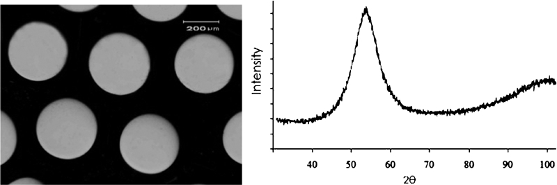
Amorphous balls of Fe–Ni–Co–Mo–B–Si alloy produced by controlled in flight cooling of UDS droplets47
With controlled secondary in-flight quenching, as illustrated in Fig. 6b and c, particulate materials with highest rapid solidification effects can be produced directly from the melt. Such rapid solidification powders may have cost advantage over melt spun and comminuted powders, which could suffer also from contamination.
In droplet deposition with UDS, monosize droplets in a desired thermal state are deposited onto a substrate to form a dense deposit with novel rapid solidification microstructures that cannot be produced by conventional spray deposition. Unlike conventional droplet or spray deposition processes, the UDS process, because all droplets have the same liquid fraction, can produce deposits with virtually full density.18,48– 50 As seen in Fig. 9, the depositing droplets can be superheated, undercooled or mushy, and can even be controlled to be at desired temperature and fraction solid. Deposition of mushy droplets with controlled amount of liquid produces deposits with an equiaxed microstructure displaying uniform grain size and essentially no porosity. Deposition of molten droplets with controlled temperature produces deposits with novel columnar and single crystalline structures by incremental epitaxial growth (Figs. 10 and 11).50,51
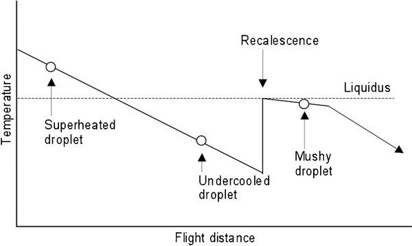
Thermal states of depositing droplets in UDS deposition
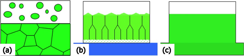
Three modes of deposit growth in UDS deposition
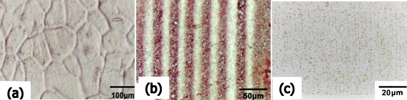
Novel microstructures produced by UDS deposition
Production rate
A hurdle in commercialising UDS is the low production rate. The number of droplets that a single orifice generates is limited by the frequency of the imposed vibration that depends on the diameter of the droplets generated. For example, 200 μm droplets are generated at a rate of ∼20 000 droplets/s. This translates into a production rate of 0·5 kg h−1 for aluminium and 1·5 kg h−1 for steel. Although this may be sufficient in the production of solder balls used for IC packaging, development of multiple orifice UDS (MO-UDS) nozzles is critically required for commercial production of most other types of powders and spray deposits.52 Preliminary lab scale experiments, as seen in the snapshot of a MO-UDS experiment with an aluminium alloy in Fig. 12a,16 suggest that MO-UDS is in principle viable for the commercial production of powders and spray deposits. With a 1000-orifice UDS nozzle, the production rate in mass could be increased to the range of a few metric tons per hour for steel. Figure 12b shows a schematic of thin slab spray forming by MO-UDS with linear orifice configuration. Other potential areas of application include spray casting of complex alloy billets and ingots.
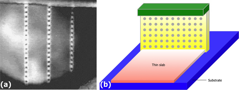
Multiple orifice UDS
Conclusions
Monosize molten metal/alloy droplets generated by the controlled capillary jet break-up have virtually identical motion and as such solidify along an essentially identical path while travelling in the cooling gas, enabling droplet based solidification processing at the highest levels of microstructure control. Methods were developed for the characterisation and control of the nucleation kinetics and in-flight solidification of monosize droplets. The jet break-up process is applicable to advanced particulate and bulk materials processing. Particulate materials with uniform rapid solidification microstructure are obtained by the in-flight solidification or fluid/substrate quenching of monosize droplets at a desired droplet thermal state. Bulk materials with novel microstructures are obtained by depositing superheated, undercooled or mushy monosize droplet sprays on a substrate. The ability to predict the nucleation kinetics also applies to the molten droplets of conventional sprays for which droplet cooling behaviour is known. Commercialisation has been achieved in IC packaging, and research and development is in progress for other applications. Multi-orifice spraying leads to high rate production.