
Abstract
A constitutive model is proposed for the densification of metal powder during hot isostatic pressing. The model considers an inelastic deformation resulting from time dependent (viscoplastic) and time independent (plastic) mechanisms during loading. With employing the Abouaf's formalism for viscoplastic part, the paper is focused mainly on the plasticity contribution including the hardening effects of both relative density and the equivalent plastic strain. The proposed plastic–viscoplastic model is summarised to an equation expressing the densification rate under hydrostatic loading. The gas atomised 316LN stainless steel powder was used in this study. Model parameters necessary for simulation of HIP process during a given pressure ramp at constant temperature are identified using previously published data. The identified model is then verified using experimental data obtained from HIP trials performed at another fixed temperature but with varied pressure ramp rates. A good agreement was found between the model prediction and the experimental results.
Introduction
Because of its advantages such as energy and material savings, modelling thermomechanical behaviour of materials during fabrication process has increased during recent decades. There has been considerable interest to model the process of hot isostatic pressing (HIP) in the field of powder metallurgy. However, complex HIP cycles with different temperatures and pressure ramp rates are common within industrial practices. These facts as well as the presence of can resistance preventing a perfect and uniform transfer of applied pressure and temperature to the powder make it difficult to obtain a simple analytical relationship between HIP parameters such as pressure and temperature and the results of material deformation such as compact density or dimensional changes. This is why a modelling work on material behaviour consists usually of constitutive equations for both powder and the can surrounding powder. The constitutive equations are then integrated in a numerical procedure such as finite element analysis in order to predict the material deformation during the HIP cycle. However, it is evident that some valid constitutive models must be used in the numerical procedure in order to obtain reliable results.
There are two approaches that are commonly used to model the compaction of metal powder. The first one is a rate independent plastic modelling that is appropriate for cold compaction processes such as metal powder compaction in a closed die at ambient temperature and the second one is the rate dependent viscoplastic modelling that is applicable for powder compaction processes at relatively high temperatures such as the holding stage in a HIP process. In other words, the inelastic deformation mechanisms are considered to have a rate independent plastic nature in the former and a rate dependent viscoplastic nature in the latter. The work reported for modelling of the compaction of metal powder is essentially classified in these two categories.
For modelling the plastic behaviour of metal powders, it is possible to consider a yield function as an extension of von Mises yield criterion. The extension is made by taking into account the effect of hydrostatic pressure on materials’ inelastic deformation in addition to the second invariant of stress deviator. In this category called as porous material model, several models have been introduced.1–5 This type of modelling may not be useful for the initial stage of compaction where the particle rearrangement and not the particle plastic deformation is the main mechanism of densification. 6 In fact, for the initial stage of compaction, we deal with a granular material and we should thus use a granular material model. Brown and Abou-chedid 7 suggested the usage of two-mechanism models to cover the whole range of powder compaction. An improvement in the modelling works is the consideration of strain hardening of matrix material into account.8,9 It is interesting to note that in the work of Sun et al. 8 the model of Shima and Oyane has been used with considering the hardening effects of matrix material although the original version of Shima and Oyane's does not consider these effects. As the model of Gurson and that of Fleck et al. 9 are appropriate for low and high porosity ranges respectively, Redanz 10 has used a combination of two models to simulate the whole cycle of compaction from high to low porosities with considering a power law behaviour for matrix material. It was seen that hardening of matrix material could have a significant influence on the evolution of applied load as well as the stress in the piece.
For modelling rate dependent (viscoplastic) deformation of metal powder, many works have been previously reported. Following Cassenti, 11 Abouaf et al. 12 presented a constitutive modelling applicable to hot isostatic pressing of metal powders. In fact, the Norton power law creep of matrix material 13 was extended to the case of porous media in the work of Abouaf et al. 12 By considering a modified form of hyperbolic sine equation proposed by Raboin 14 for the matrix material and using the model suggested by Abouaf et al., 12 Svoboda et al. 15 simulated HIP of metal powders. Bouvard 16 and Bouvard and Ouedraogo 17 have modelled the HIP process with considering power law creep for the matrix material. The behaviour of metal powders has also been considered based on a diffusional creep mechanism occurring on the interparticle contacts. 18 Storakers et al. 19 consider the early stage of cold and hot compaction by a viscoplastic modelling. They consider a viscosity hardening equation for uniaxial deformation of matrix material 20 making it possible to be used in a large range of temperatures. Govindarajan and Aravas, 21 Aryanpour, 22 Wikman et al. 23 have also applied plastic–viscoplastic modelling to describe materials’ inelastic deformation in HIP process. They assume in fact an inelastic deformation due to simultaneous effects of plasticity and viscoplasticity.
The present work describes a phenomenological constitutive modelling in which the inelastic deformation is proposed to consist of rate independent plastic and rate dependent viscoplastic parts. It is thus classified in the plastic–viscoplastic category. After presenting the general constitutive equations, the expression applicable to the pressure ramp of HIP process at a constant temperature is derived. Integration of this expression results in density as a function of time during the pressure ramp. The parameters in this equation are identified using data from prior HIP experiments carried out at the pressure ramp stage on 316LN stainless steel metal powder. Then, the model predictability is verified against new HIP experiments carried out at different pressure ramp rates other than the one utilised to identify the model parameters.
Modelling
General concept
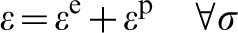
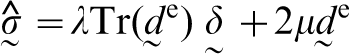
As stated previously, an elastoplastic–viscoplastic modelling is introduced in this work. The isotropic Hook elasticity is assumed for elastic behaviour of the material. However, the inelastic deformation is decomposed into plastic and viscoplastic parts. From a physical point of view, one can consider that there would be permanent deformation mechanisms whose characteristic time is much less than the loading time and in this case the time independent plastic deformation occurs. On the other hand, it could be considered that there are some other permanent deformation mechanisms with characteristic time comparable with the loading time. 24 Presence of these mechanisms leads to the time dependent deformation. The coexistence of time dependent and time independent mechanisms could be apparent when we think of dislocation slip and disclocation creep as two phenomena being active simultaneously in material deformation in the loading condition at relatively high temperatures. Dislocation slip and dislocation creep are considered as two sources of plastic and viscoplastic behaviours respectively. After this assumption, two general points are remarked:
a plastic problem can be usually treated by a classical approach including yield criterion. However, care must be taken when dealing with plastic deformation simultaneously with viscoplastic deformation. This subject will be further discussed in the subsequent sections
different assumptions can be made for viscoplastic behaviour.25,26 However, in this work, we consider secondary creep as the most important contribution of time dependent inelastic deformation in comparison with primary and tertiary creeps.
In the following sections, first the viscoplastic and plastic modelling approaches are described separately and then the plastic–viscoplastic modelling that is the main topics of this work will be presented.
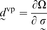
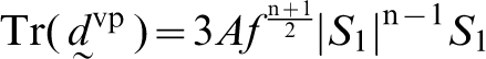
Viscoplastic modelling
Depending on the material, temperature and loading conditions, it can be considered that all of the inelastic deformation in material occurs due to viscoplastic behaviour. For example, during the holding stage in a HIP process, a viscoplastic model such as Abouaf's model is adequately appropriate to describe material deformation. In the following a brief review will be done on this model. In fact, Abouaf's model is an extension of Norton power law creep model for the porous material. The Norton power law used to describe secondary creep of dense material in a uniaxial test is given by the following equation
 is an invariant of the stress deviator tensor. If
 is the Cauchy stress tensor, we have
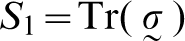
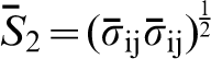
 is the stress deviator tensor given by
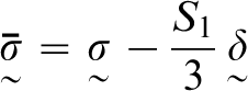
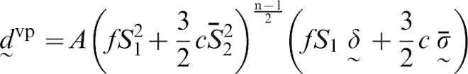
 is the Kronecker delta, and f and c are two functions of relative density of the material and are defined as the following equations
Plastic modelling
Plasticity of non-porous material in uniaxial test
Consider the elastoplastic behaviour in uniaxial test. A common formalism to describe material behaviour is the Ramberg–Osgood's equation
Plasticity of porous material
If we consider deformation of the material at relatively low temperatures, the rate independent mechanisms are basically responsible of material's inelastic deformation. In such cases, with maintaining loading condition, the classical plasticity theory is applied so that the following concepts are introduced to calculate plastic deformation rate tensor:
yield criterion or yield function that defines a surface in the stress space. If the state of stress is found on the yield surface then the plastic deformation will occur provided that the loading condition is conserved. The yield criterion is shown by

the consistency condition states that the variation rate of F is zero during plastic deformation

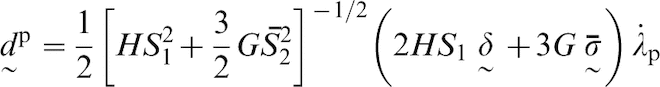
an associated flow rule is usually applied to calculate the plastic deformation rate tensor
 of porous metal
 is the plastic multiplier.
The main task among the three steps stated above is to introduce a yield function (F = 0). Based on physical phenomenon occurring during compaction of the metal powder, the plastic deformation of metal particles could result in the flattening of interparticle contacts leading to the material densification. This point is schematically shown for deformation of two spherical particles in Fig. 1.
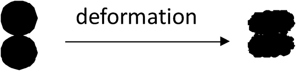
Flattening of particle contact due to plastic deformation
Moreover, based on the materials engineering concepts such as dislocation glide and thus dislocation generation during plastic deformation, metal particles will be strain hardened during compaction. Hence, work or strain hardening of particles and increasing material density are two simultaneous phenomena when plastic deformation of metal particles is considered. Therefore, material relative density ρ and the equivalent plastic strain
 could be considered as two isotropic hardening parameters for plastic deformation. In other words, porous material strengthening (work hardening) is influenced by both relative density and equivalent plastic strain
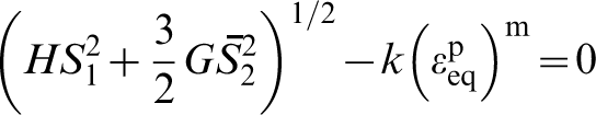
 . Therefore, the simultaneous application of Green's porous metal plasticity formalism and Ramberg–Osgood's power law formalism in the yield function enables us to take into account both effects of relative density and equivalent plastic strain respectively in material hardening. The following yield function is thus introduced
 and ρ, the yield function defines an ellipse in the plane of
 versus S1. Aryanpour and Farzaneh
27
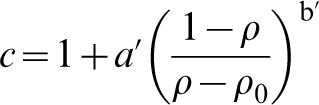
have studied porous material plasticity based on the equation (18). They have considered different situations for the initial material strain hardening state and relative density. As example, one can consider the situation that there are point-like contacts between particles and the initial stain hardening of particles is null. This situation means that the initial relative density is equal to ρ0 and the initial equivalent plastic strain
versus S1. Aryanpour and Farzaneh
27
have studied porous material plasticity based on the equation (18). They have considered different situations for the initial material strain hardening state and relative density. As example, one can consider the situation that there are point-like contacts between particles and the initial stain hardening of particles is null. This situation means that the initial relative density is equal to ρ0 and the initial equivalent plastic strain
 is equal to zero. In this case, the yield function (equation (18)) is obviously valid from the beginning of loading. With considering constant temperature, applying equation (16) results in

 and
and
 are the rates of S1 and
 respectively resulted from the Jaumann rate of Cauchy stress
 and
and
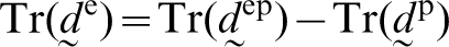
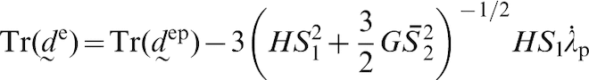
 is the variation rate of relative density due to plastic deformation. From equation (17), we can write
 can be obtained from the principle of mass conservation
 in equation (21) is the variation rate of
 and can be written as
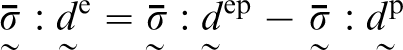
If elastic deformation occurs along with the plastic one, we can write
 and
and
 are the elastic and elastoplastic deformation rate tensors respectively. We can also write
 as the following equation
 ) can be formulated in another way
The elliptical curve characterised by some values of ρ and
 shows the position of yield surface in the
 plane (Fig. 2). It is considered that the yield surface during an elastoplastic deformation process is expanded due to the increase in relative density and material equivalent plastic strain that are considered as the isotropic hardening parameters.
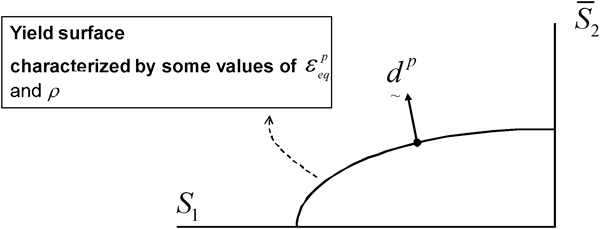
Schematic illustration of elliptical yield surface and plastic deformation rate
Plastic–viscoplastic modelling
A typical HIP cycle may often involve some large variation of temperature and pressure. For example, a HIP process including ramp stages starting from low values of pressure and temperature and ending to some high values of these parameters is considered. In such situations, material's inelastic deformation may be described by a plastic–viscoplastic approach. According to physical phenomena occurring during deformation, it is comprehensible that certain deformation mechanisms may be so rapid (i.e. plastic mechanisms) in comparison with loading times applied in practice and other deformation mechanisms may be active in slower rates (i.e. viscoplastic mechanisms). Therefore, we adopt a plastic–viscoplastic approach in this work. Aryanpour
22
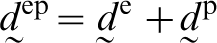
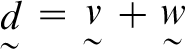
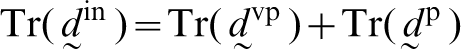
has previously applied such a modelling in which Abouaf's model and Green's model were selected to describe viscoplastic and plastic parts of deformation respectively in a way that material relative density is the unique scalar hardening parameter. However, in this work the plastic model is modified with inclusion of equivalent plastic strain as an additional hardening parameter. The general expression of deformation rate applicable to any loading path will be presented in the following. To obtain the necessary formulation, the deformation rate tensor at a material point
 is assumed to be the sum of two functions
 and
and
 are supposed to be two homogeneous tensorial functions such that
 is of order null with respect to time and
 is of order n with respect to
 . Therefore,
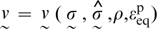
 and
and
 can be considered as two functions describing rate independent elastoplastic and rate dependent viscoplastic deformation rate components respectively
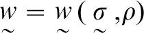
 and
and
 are as follows:
parameter ρ in both
 and
and
 is the relative density resulting from both plastic and viscoplastic deformations
since Abouaf's model as an extension of secondary creep is used to model viscoplastic deformation, it is thus considered that the strain resulting from viscoplastic deformation does not contribute towards material's strain hardening in plastic behaviour. In other words, only the plastic contribution of equivalent inelastic strain, i.e.
 is considered in addition to the material relative density to describe plastic behaviour (see equation (43)).
From above definitions of function
 and
and
 , the Abouaf's model explained in the section on ‘Viscoplastic modelling’ and the plastic model explained in the section on ‘Plastic modelling’ are selected to formulate the elastoplastic–viscoplastic modelling. We can thus simply use equation (11) in order to calculate the viscoplastic part of deformation rate. However, for the plastic part of deformation rate, some issues must be resolved in order to obtain the explicit equation of plastic deformation rate. In fact, an important consequence of considering simultaneous effects of plasticity and viscoplasticity is to obtain some assumed values of relative density and equivalent plastic strain at a stress state that is located within the interior of the yield surface characterised by the assumed values of relative density and equivalent plastic strain. Figure 3 illustrates this concept where the values of relative density and equivalent plastic strain are obtained at a stress state shown by point B within the interior of the elliptical yield surface defined by equation (18). Concept of onset of the plastic deformation from the beginning of material loading instead of an elastic limit analysis for dealing with plastic behaviour has been previously suggested.22,25,28 We follow the same concept in this work and make this hypothesis that even in the condition of point B located within the interior of yield surface (Fig. 3), a plastic deformation occurs at point B in the condition that the loading condition is satisfied. In the following, the expression of deformation rate tensor at a point such as B will be presented. For this aim, consider the following points that are also illustrated in Fig. 3:
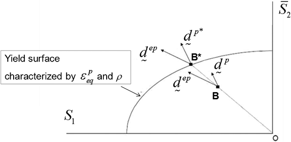
Schematic illustration showing plastic deformation rate at point B located within interior of yield surface with considering elastoplastic–viscoplastic behaviour for material
the point B* shows a stress state located on the yield surface and obtained from radial projection of point B on the surface
as the position located on the yield surface is shown by an asterisk, equation (38) can be rewritten as follows where an asterisk is used to define the parameters at point B*
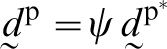
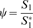
 . As the same ratio is conserved between the stress components at B and B*, one may make the hypothesis that
 is proportional to
 by a proportionality factor ψ such that
 is defined by equation (47). Therefore

 in equation (49) could be replaced with the following equation
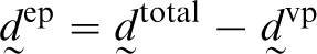
 is the total deformation rate tensor.
Application of plastic–viscoplastic modelling
The HIP process is used for compaction of metal powders by simultaneous application of temperature and isostatic pressure on the parts. Typically, pressure and temperature are applied at a certain ramp rate until desired values are reached. The densification of metal powder during this ramp stage may be important and should thus be accounted in the approach being used to model densification during HIP. In this study, the HIP cycles were carried out such that the pressure is ramped with certain ramp rate at a constant high temperature. This allows the decoupling of the simultaneous effect of pressure and temperature by keeping the temperature constant while increasing the pressure as illustrated schematically in Fig. 4. For the ramp stage presented in Fig. 4, it is assumed that during each time increment, a time independent plastic deformation occurs due to increase in pressure (pressure increment), whereas a time dependent viscoplastic deformation occurs due to the applied hydrostatic pressure, simultaneously at the constant high temperature.
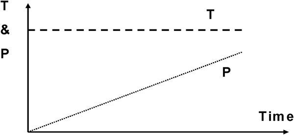
Pressure ramp applied at relatively high temperature may be part of different HIP cycles
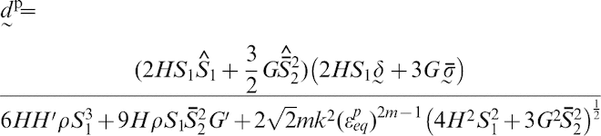
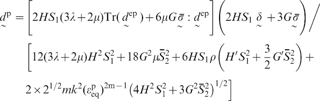
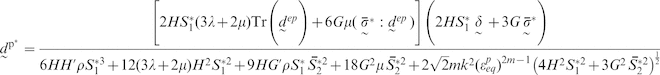
If the container used for powder encapsulation is very thin and the applied temperature is relatively high, one may assume a perfect transfer of hydrostatic pressure to the powder by neglecting the container resistance. Hence we can apply the plastic–viscoplastic model to describe metal powder inelastic deformation under an increasing hydrostatic pressure at a constant high temperature (Fig. 4). To apply the general equation, i.e. equation (49), for the particular case of pressure ramp in HIP process, we transform first equation (49) to its equivalent expression applicable for stress driven processes. To realise this task, we follow a mathematical procedure inversing to what was explained from equation (28) to equation (41). The final result is

 is null, equation (51) changes to the following equation
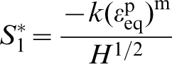
 ) where ψ could be assumed as below
 is null
 in hydrostatic loading, one can write
 and then applying equation (55) result in
 , one can write
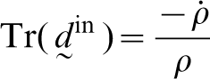
 is the rate of change of relative density. In hydrostatic loading we have
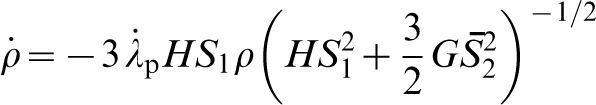
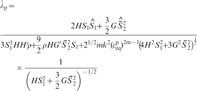
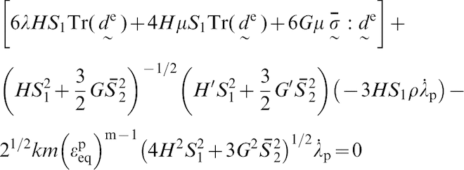
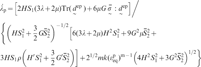
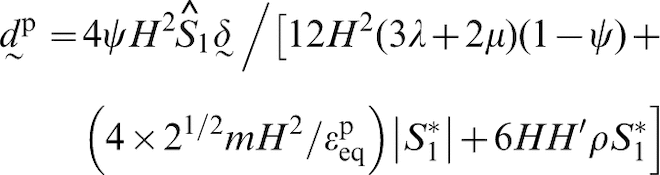
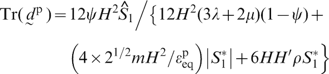
 are the pressure and pressurisation rate respectively. Using the equations (57)–(60), we can thus write
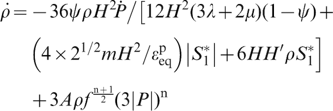
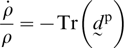
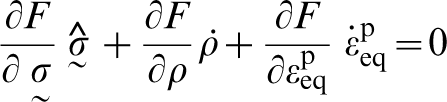
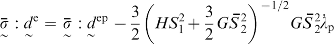
 . This is the useful expression resulted from the suggested plastic–viscoplastic modelling that can be applied to describe the powder densification during a pressure ramp at a given temperature. This equation is solved numerically to obtain the evolution of density as a function of time at given temperature and pressure ramp rate.
Model identification
Assuming that 316L and 316LN stainless steel have similar themomechanical behaviour, the comprehensive experimental data published in the literature22,29,30,31 for these two materials can be used to identify following parameters.
Young's modulus E and Poisson's ratio ν of porous material
The Poissons’ ratio is considered to be equal to 0·33 in this work. However, the following expression is considered for E as a function of realtive density

k and m
Uniaxial tests on 316L stainless steel between 450 and 600°C
30
show that the material behaviour in this temperature range is essentially elastoplastic. In fact, no dependence on deformation rate was seen in the material uniaxial test in this temperature range. It is thus possible to apply the Ramberg–Osgood's equation to describle elastoplastic uniaxial behaviour and thus the following parametric equations are obtained


A and n
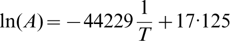
From uniaxial tests on 316LN stainless steel, the parameters A and n were found for this material for temperatures above 980°C.
31
The following parametric equations on the experimental values of A and n enable us to estimate the values of these parameters at other temperatures
22

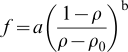
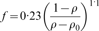
Function f
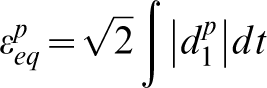
From densification experiments on 316LN stainless steel powder interrupted at different times of the holding stage in HIP tests, function f is estimated as22,31
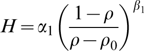
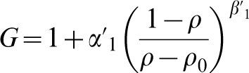
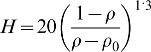
Function H
Experimental points obtained from HIP experiments on 316LN stainless steel in a pressure ramp of 2·8 MPa min−1 at 1125°C are shown by points in Fig. 5.
22
As mentionned before, we can neglect the effect of container and thus equation (63) can be used to find the values of H. Considering ρ0 equal to 0·64, function H was basically estimated by a trial end error approach as
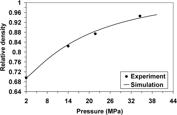
Comparison of experimental results 22 from HIP trials on 316LN stainless steel powder at 1125°C with pressurisation rate of 2·8 MPa min−1 (points) and simulation result (curve)
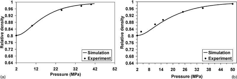
Verification of identified model parameters against experimental results from HIP trials 31 on 316LN stainless steel powder at 1125°C with pressurisation rates of a 0·5 MPa min−1 and b 1 MPa min−1
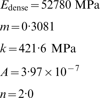
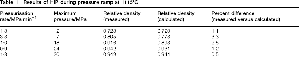
The validity of the proposed model is reinforced using experimental data obtained from HIP trials on 316L stainless steel powder at various pressure ramp rates and at temperature of 1115°C, as outlined in Table 1. For these HIP trials, the powder was encapsulated in a cylindrical, low carbon steel container with an internal height of 76·2 mm and an inner diameter of 17·3 mm. The container thickness was 0·89 mm. While using two or three samples for each trial, a low pressure about 0·2 MPa of argon was applied during the time that samples were being heated to 1115°C. Then, at 1115°C, a pressure ramp was applied in order to achieve a final pressure. The parameters used for each trial are reported in Table 1. As seen in this table, the pressurisation rate had a different value in each trial. After the final pressure was obtained, the furnace power was cut and the chamber pressure was released as quickly as possible. It is thus assumed that no significant densification occurs in the cooling stage. Ignoring the effects of the container, these HIP trials were also simulated by applying equation (63). It should be pointed out that the following values were selected for the temperature of 1115°C according to equations (65)–(69).
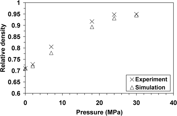
Relative density attained during five different pressure ramps Initial point (ρ = 0·71) identifies the densification due to sintering during the heating portion of the experiments. In this work, ρ0 is equal to 0·6684.
Results of HIP during pressure ramp at 1115°C
At the end of this discussion, it should be pointed out that although from a mathematical point of view, a relatively large number of parameters were needed to obtain simulation results adequately close to the experimental values, knowing their physical significance in the model allowed us to identify these parameters using well known experimental routes available in the literature.
Conclusions
Considering that the inelastic deformation behaviour of powder materials is governed by plastic and viscoplastic mechanisms, an elastoplastic–viscoplastic model was proposed for densification of metal powders during compaction process such as hot isostatic pressing of metal powders. In this model, relative density and equivalent plastic strain are considered as two isotropic hardening parameters influencing the plastic component of the model while the viscoplastic component is uniquely influenced by relative density. After the derivation of a suitable expression for powder material's densification under hydrostatic loading, the model parameters were identified using previously published data and also from HIP trials on 316LN stainless steel at 1125°C with a pressure ramp of 2·8 MPa min−1. The model predictions are then compared with previously published results from two other series of HIP trials at pressure ramps of 0·5 and 1 MPa min−1. Finally, a test programme of HIP trials was outlined and carried out on 316L stainless steel powder at 1115°C with different pressure ramps and it was found that the simulation results were in good agreement with the experimental data. The model must be applied for more complicated loading paths including some deviator components. Some experimental routes should be outlined to identify other model parameters important in deviatoric loading.
Footnotes
Acknowledgements
The authors gratefully acknowledge collaboration, support, and in kind contributions from Bodycote HIP, Inc., Andover, MA, USA and the research group REGAL at Université Laval, PQ, Canada.