
Abstract
Aluminium alloy AA 5083 [Al–4·4Mg–0·7Mn–0·15Cr (wt-%)], powder was ball milled in liquid nitrogen via the cryomilling method to obtain a nanocrystalline (NC) structure. Samples of the powder were hot vacuum degassed to remove interstitial contaminants, then consolidated by hot isostatic pressing (HIPing) at six temperatures (from 0·46Tm to 0·89Tm), before being high strain rate forged (HSRF) to produce plate material. The microstructure was analysed at the different processing stages. The compressive properties of the as HIPed material, plus tensile properties of the final product were studied. Despite grain growth during HIPing, an ultrafine grain (UFG) structure was retained in the consolidated material, which consequently had increased strength over conventionally processed AA 5083. As the HIP temperature was increased, the density increased. Strength changes were minimal in compression and tension with varying HIP temperature, once near full density was attained at 275°C (∼0·64TM). Yield strength data indicate negligible variation in the grain size of the materials.
Keywords
Introduction
Ball milling in liquid nitrogen, known as cryomilling, of Al alloy powder results in a nanocrystalline (NC) microstructure that possesses significantly greater strength than conventionally processed materials.1,2 To produce bulk products, the cryomilled powder must be consolidated without losing the beneficial structure. Hot isostatic pressing (HIP), where the canned powder is subjected to the combined effect of pressure and temperature, has been shown to be a successful method of achieving material that is close to full density.3,4
In HIP, isostatic gas pressure is applied to a component or workpiece at an elevated temperature in a specially constructed pressure vessel. When consolidating metal powders in pressure tight, sealed compacts, the HIP process plastically deforms the powder, which eliminates porosity in the part to achieve near 100% theoretical density with HIP temperatures >0·5Tm. 5 Thousands of fully dense HIP compacts are commercially produced each year. This includes net shapes, near-net shapes, and a variety of mill forms for subsequent thermomechanical processing (TMP). In commercial applications, the elevated temperature in HIP ranges from ∼480°C for Al alloy powders to 1700°C for tungsten powders. High density argon gas is the most common pressure medium used in the process, although other gases such as helium or nitrogen can also be used. Pressures ranging from 20 to 300 MPa are possible with 100 MPa being the most common. 6
Despite the extended time at high temperature and pressure during HIP, the high thermal stability of the cryomilled Al alloy prevents excessive grain growth. 7 However, the grain size does increase and the HIPed compact normally has a microstructure composed of grains larger than 100 nm. Therefore, the structure can no longer be regarded as NC, and instead qualifies as ultrafine grained (UFG). In addition, material diffuses into and fills the interstices between the cryomilled powder particles, forming micrometre sized grains and, leading to a distribution of grain sizes. 5 Investigators have asserted that the existence of these coarse grains (CG) can contribute to the ductility in the final product. 8
To achieve ductility in NC and UFG cryomilled Al alloys and MMCs (via larger grain size, higher density, and lower extrinsic defects and artefacts) HIPing is preferred to cold isostatic pressing (CIPing). For this investigation AA 5083 [Al–4·4Mg–0·7Mn–0·15Cr (wt-%)) was the Al alloy selected. The HIPing process at UCD for Al alloys typically is performed at ∼350–400°C and 103–172 MPa with the application of isostatic pressure applied via argon while simultaneously exposing the canned powder to elevated temperature. In the HIP process, diffusion of material to prior particle boundaries (PPBs) occurs during densification. The diffusion process leads to a bimodal or multimodal grain structure, because the PPBs are typically larger than the grains within the individual particles. Because HIPing does not involve a large shear component to the deformation, HIP is best used for densification only.9,10 An as HIPed billet typically will not provide the ductility needed for a structural component as the PPBs will retain the previously formed nascent oxide layer of the Al powder. Tang et al.11,12 showed this in work on cryomilled AA 5083 and AA 5083–SiC MMCs, and they also showed the distribution of the oxide layer after extrusion in an Al–SiC MMC.
The ductility of as HIPed cryomilled powder is usually low, with tensile elongations less than 1%. Owing to the isostatic nature of the HIP pressure, the PPBs are retained, and these boundaries act as sites for crack nucleation and premature failure. To achieve reasonable ductility (defined here as >4%), a subsequent deformation step is typically employed that involves shear strains to break up the prior particle boundaries. This is normally achieved by a combination of extrusion, forging and/or rolling, depending on the final product required. In this work, to achieve plate geometries, high strain rate forging (HSRF) is employed as a forming step. The HSRF process retards grain growth during deformation because of the high strain rate involved, typically on the order of 102 s−1. 13
Cryomilling AA 5083 powder has received interest because of the potential to reduce the weight of military ground vehicles. With this application in mind, it is important to ensure that even though the cryomilled system has increased strength, the survivability of the alloy is not jeopardised. Therefore, retention of ductility, in addition to increased strength, is essential to this material system if it is to be used for structural parts in military vehicles. 14
Inspection of the published literature reveals few studies on the optimisation of HIP parameters to improve the properties of consolidated cryomilled powder. In this paper, we report the effects of HIP temperature, ranging from 0·46Tm to 0·89Tm, on cryomilled AA 5083. We present and discuss the microstructures and mechanical properties before and after high strain rate forging (HSRF) to achieve the final plate geometry.
Experimental procedure
Materials processing
Precursor powders for these plates were generated from a 20 kg batch of atomised − 325 mesh (<44 μm) AA 5083 powder (Valimet, Stockton, CA, USA), which was cryomilled in liquid nitrogen (LN2) (DWA Aluminum Composites, Chatsworth, CA, USA) for 8 h in a modified Szegvari attritor. Stainless steel (440C) milling balls were used with a ball-to-powder weight ratio of 32∶1, and 40 g (0·2 wt-%) stearic acid (e.g. octadecanoic acid CH3(CH2)16COOH) 15 was added as a PCA to improve yield. After milling, the powder was transferred to a glove box under LN2, ensuring that atmospheric contamination of the cryomilled powder was minimised.
Six samples of the cryomilled powder, each 1·16 kg, were used to fill welded AA 6061 cans ∼100 mm diameter and 125 mm internal length. The powder was then hot vacuum degassed at UC Davis by heating cans individually to 500°C in a tube furnace and applying a vacuum of ∼10−6 torr through a stem in the can lid. After 20 h at 500°C, a valve on the stem was closed, the can was cooled to room temperature, and the stem was sealed permanently by crimp welding.
The cans of degassed powder were individually HIPed at UC Davis (Flow Autoclave MIH-9) at 103 MPa for 4 h at six different temperatures: 125, 200, 275, 350, 425 and 500°C. A slice ∼13 mm thick was taken from near the bottom of each can for characterisation of the as HIPed structure. The remainder of the HIPed material was machined to remove the canning material down to cylindrical billets of approximate diameter 65·0 mm and height 76·5 mm.
The HIPed billets, which are henceforth labelled MCs 32–34 and 37–39, were preheated in an air furnace at 400°C for 1 h, and then high strain rate forged (HSRF) using a Dynapak press (Model 1220C) high velocity impact machine, as shown in Fig. 1, with an initial ram speed of ∼6 m s−1 by Pittsburgh Materials Technology, Inc. (PMTI) (Jefferson Hills, PA, USA) into an oversized die, 121 mm square and 19 mm thick. The resultant forgings had rounded corners and were 19·3–19·6 mm thick. The edges were trimmed to ∼102 mm square and faces machined so that the final thickness was 19 mm. Figure 2 shows high speed photographs of a similar forging sequence at PMTI.
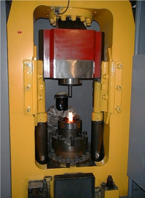
Dynapack Model 1220C in used for forging
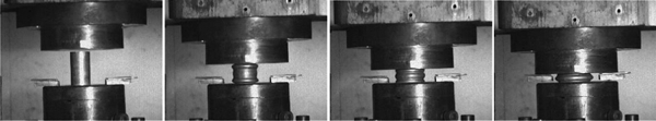
High speed video images taken during Dynapak HSRF (PMTI, Jefferson Hills, PA, USA) of AA 5083 in stainless steel sheath using fire pressure of 5·5 MPa (800 psi) and billet preheat temperature of 450°C at −1·5, 4·5, 8·0 and 14·0 ms relative to impact, from left to right
Characterisation
Metallic alloying elements were measured using DC plasma emission spectroscopy, according to ASTM E 1097-03 by (Luvak, Boylston, MA, USA). The concentration of non-metallic elements was measured by (LECO, St. Joseph, MI, USA) using RH404 (H), TCH600 (O) and CS600 (C) analysers. Density measurements were performed using an AccuPyc-1330 Ar gas displacement pycnometer (Micromeritics, Norcross, GA, USA) with a 3·5 cm3 chamber, at least 80% of which was filled by the samples. At least four sets of 20 measurements were made for each material, achieving an accuracy of better than ±0·001 g cm−3. To account for interconnected porosity, density was also measured by a modified Archimedes’ method.
Standard metallographic techniques were performed on the as HIPed and as forged material for examination in an AHMT3 (Olympus, Center Valley, PA, USA) optical microscope. Polished samples were etched with detergent to emphasize coarse grained regions. Image analysis was carried out using Fovea Pro 2 software on 10 images of unetched material to determine the amount of porosity, and on the etched as HIPed billet to measure the area (volume) fraction of coarse grained regions. Sliced samples were thinned for examination by jet polishing in an ethanol solution containing 8% perchloric acid +10% 2-butoxyethanol. The mean grain size was obtained from the TEM images (Philips EM420 TEM). Samples were viewed in different directions with respect to the forging by two methods. First, a linear intercept method was employed, where ∼50 lines were drawn in perpendicular directions on TEM images taken at a magnification of ×37 500. Second, the maximum dimensions of 400 individual grains were measured and data were used to generate a grain size histogram.
Sections near the centre of the plates were cut and machined to produce flat dog bone tensile specimens with a gage section 12×4×2 mm, the long axes being normal to the forging axis. Tensile testing was carried out at a nominal strain rate of 10−3 s−1 using an Instron (Norwood, MA) 8801 servohydraulic universal testing machine equipped with a standard video extensometer to measure strain.
Results
Six materials were investigated after HIPing at different temperatures (identification numbers in parentheses) – 125°C (MC 39), 200°C (MC 38), 275°C (MC 34), 350°C (MC 32), 425°C (MC 37), and 500°C (MC 33). The HIPed billets were subsequently forged at PMTI via the HSRF method. The microstructures were characterised after HIP and after HSRF, and mechanical properties were investigated at both stages of processing.
HIPed billet porosity
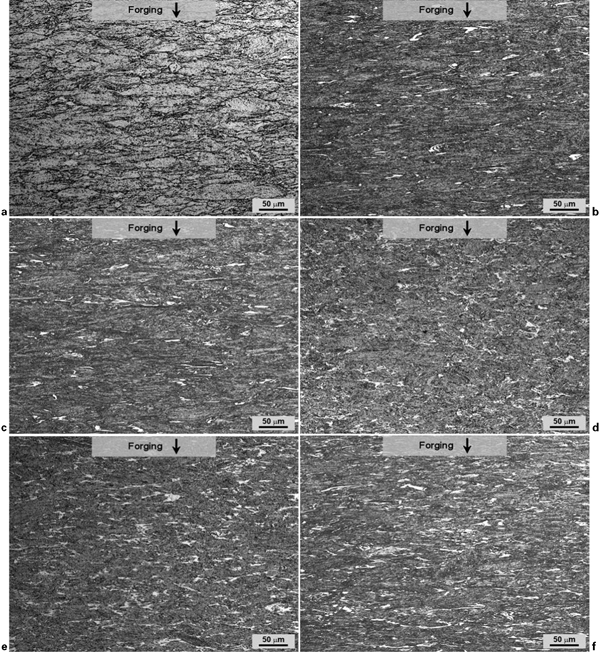
The cryomilled powder HIPed at 125°C (the lowest temperature, MC 39), contained extensive porosity, much of it interconnected, as shown in Fig. 3a. Porosity levels were similar to those obtained by CIP, where ∼85% density is considered high. 6 The porosity was so high that Ar gas pycnometry could not be used to obtain a reasonable value for the density, and the modified Archimedes method was used to obtain a value of 2·31 g cm−3, <87% of the standard density for AA 5083, 2·66 g cm−3.
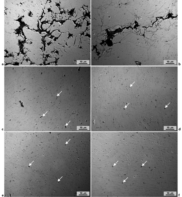
a MC 39 (125°C); b MC 38 (200°C); c MC 34 (275°C); d MC 32 (350°C); e MC 37 (425°C); f MC 33 (500°C)
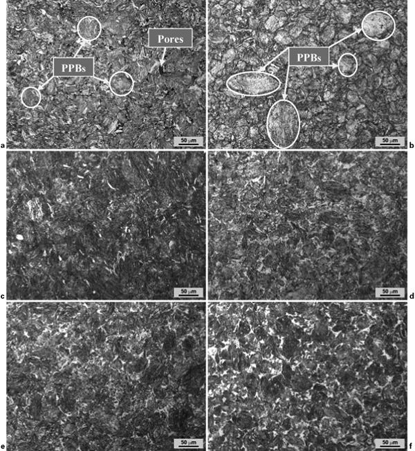
When the HIP temperature was increased to 200°C, the density of the as HIPed billet increased substantially (to 2·65 g cm−3). However, as shown in Fig. 3b, large interparticle pores were still present in the structure. At HIP temperatures of 275°C and above, the density of the HIPed material continued to increase with respect to HIP temperature, as shown in Table 1. The density of material HIPed at 500°C was close to 2·67 g cm−3. Although the powder HIPed at 275°C and above resulted in material with density above that of standard AA 5083, the structure still contained some porosity, as shown by the unetched optical micrographs in Fig. 3c and d . Figure 4 shows the materials after etching, where pores and PPBs appear more conspicuous at lower HIPing temperatures, especially in MC 39 and 38, HIPed at 125 and 200°C respectively.
a MC 39 (125°C); b MC 38 (200°C); c MC 34 (275°C); d MC 32 (350°C); e MC 37 (425°C); f MC 33 (500°C)
Density measurements for as HIPed billets and HSRF plates
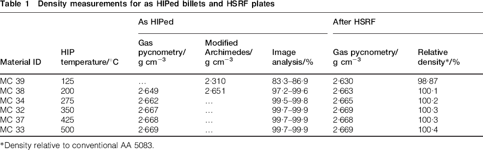
*Density relative to conventional AA 5083.
Non-metallic impurities
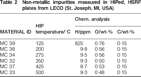
In general, the degassing procedure yielded material with reproducible non-metallic impurity levels, as shown in Table 2. Apart from the high levels of impurities measured in the sample HIPed at 125°C, due to atmospheric contamination arising from incomplete densification and the presence of interconnected porosity, the H and O levels were in the range 8·7–9·8 ppm and 0·48–0·56 wt-% respectively. The amount of carbon in all the material was consistent at 0·15 wt-%. The remaining H and C were attributed to remnants of stearic acid in the material. 15
Non-metallic impurities measured in HIPed, HSRF plates from LECO (St. Joseph, MI, USA)
HSR forged billet porosity
In general, forging increased the density of the as HIPed billets, as also shown by Table 1, although the increase was small for those materials that were already close to full density. Consequently, compared to the as HIPed material, a similar trend of density with respect to HIPing temperature was observed for the forged material, i.e. a rapid increase in density at low temperatures, and slight increases above 200°C.
Microstructural characterisation
For the HSRF material, increasing the HIPing temperature increased the amount of coarse grained regions in the forged structure, as shown in Fig. 5. The most notable difference is between Fig. 5b and f , where the coarse grain regions are indicated by the lighter tones in the micrographs in the fully dense materials HIPed at 200 and 500°C respectively. In the case of the forging HIPed at the lowest temperature (125°C) no coarse grained regions were observed and the PPBs were distinct, as shown in Fig. 4 (for as HIPed) and Fig. 5 (for HIPed and HSRF). Also, the PPBs were increasingly disrupted at higher HIPing temperature, and the coarse grained regions increased, most likely due to diffusion during HIPing. 2
a MC 39 (125°C); b MC 38 (200°C); c MC 34 (275°C); d MC 32 (350°C); e MC 37 (425°C); f MC 33 (500°C)
The four densest plates, MCs 34, 32, 37 and 33, were further characterised via TEM, shown in Figs. 6–9, to determine grain size after the HSRF step. Grain size data show a weak dependence on HIP temperature. The nature of the grain size distributions hints that well distributed PPBs may also play a role in grain growth during the secondary processing step, where the lack of a well defined nascent oxide layer facilitates further grain growth. 16 Grain sizes and aspect ratios are tabulated in Table 3.
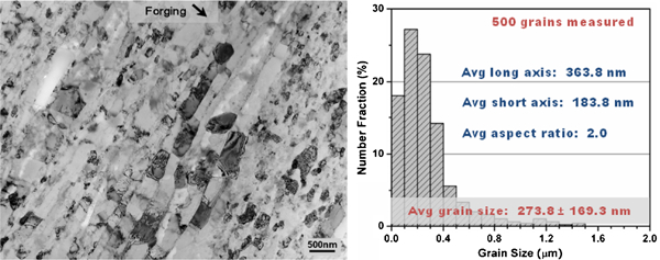
Image (TEM) of MC 34 (HIPed at 275°C) after HSRF at 400°C with corresponding histogram showing grain size and distribution
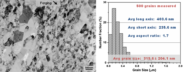
Image (TEM) of MC 32 (HIPed at 350°C) after HSRF at 400°C with corresponding histogram showing grain size and distribution
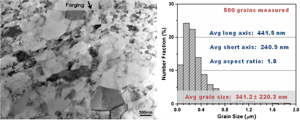
Image (TEM) of MC 37 (HIPed at 425°C) after HSRF at 400°C with corresponding histogram showing grain size and distribution
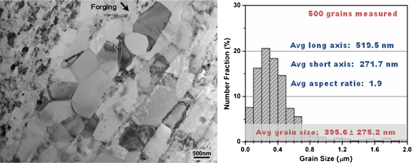
Image (TEM) of MC 33 (HIPed at 500°C) after HSRF at 400°C with corresponding histogram showing grain size and distribution
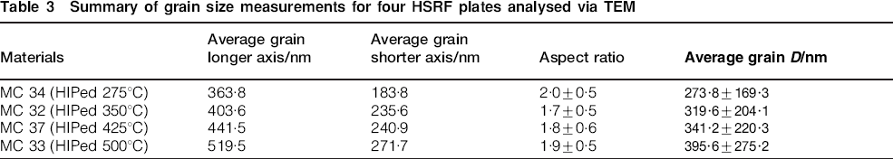
Summary of grain size measurements for four HSRF plates analysed via TEM
Mechanical behaviour
Compressive stress strain curves were generated for the as HIPed billets to ascertain the effect of HIP temperature on strength. The compression tests were conducted following ASTM E9 standards 17 but used a higher strain rate than typical quasi-static tests at UC Davis (10−1 instead of 10−3 s−1) in an effort to simulate possible forging conditions. The data in Fig. 10 show slight differences for each temperature, with the exception of the lowest temperature billet (MC 39), which failed early due to the high level of porosity. Compressive data are summarised in Table 4.
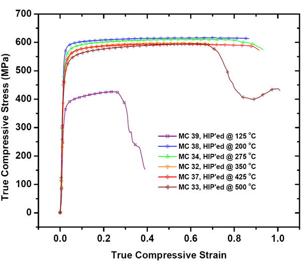
Compressive true stress–strain curves for as HIPed specimens showing variation of strength with HIP parameters
Summary of compressive properties for as HIPed billets, MCs 32–34 and 37–39*
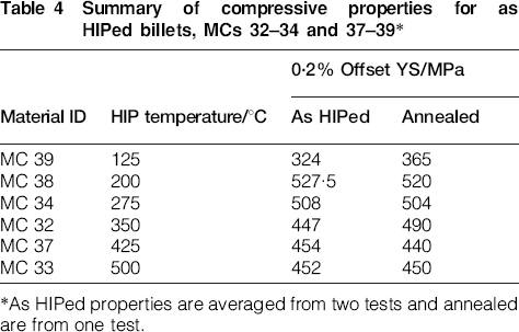
*As HIPed properties are averaged from two tests and annealed are from one test.
Tensile tests on all six HSRF billets also showed a tightly grouped data set, as seen in Fig. 11, with the biggest difference occurring with MC 33 (HIPed at 500°C). One tensile specimen of each billet was later annealed at 415°C for 30 min to negate the possibility of dislocation hardening during the HSRF process. The stress–strain curves in Fig. 12 show the effect of annealing was small, but analysis, provided later in the discussion, shows the changes are not insignificant. Data for conventional AA 5083 H131 (strain hardened) and O (annealed) are included for comparison in the both figures. Tensile data are summarised in Table 5.
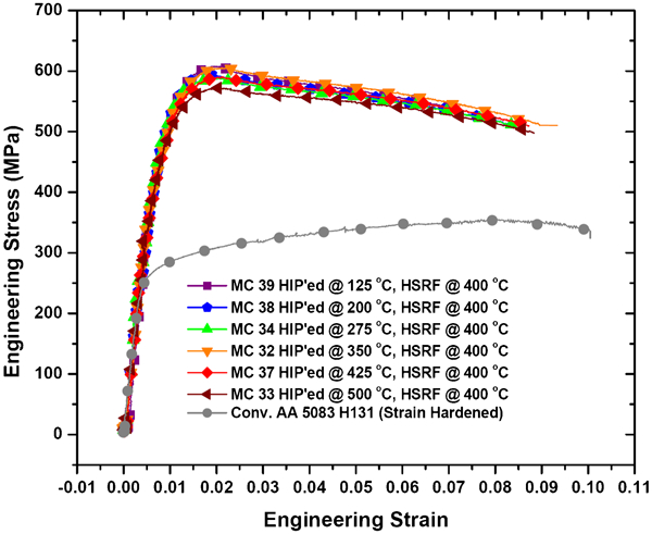
Representative tensile stress–strain curves for HSRF plates before annealing, with conventional AA 5083 H131 for comparison
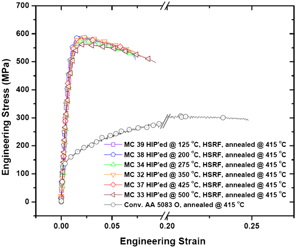
Representative tensile stress–strain curves for HSRF plates after annealing, with conventional AA 5083 O for comparison: x axis, representing strain, is broken to emphasise similarity of data for cryomilled, HIPed and HSRF plates before and after annealing
Summary of tensile properties for HSRF plates, MCs 32–24 and 37–39, before and after annealing*
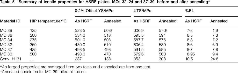
*As forged properties are averaged from two tests and annealed are from one test.
†Annealed specimen for MC 39 failed at radius.
Discussion
HIP parameters and apparent density
An important objective motivating the fabrication of these plates involves understanding the influence of HIP temperature on the consolidation, microstructure and final properties of the AA 5083 plates forged after HIPing. The micrographs in Fig. 3 clearly show a reduction in porosity with increasing HIP temperature for the HIPed billets, and Fig. 13 plots the density for the as HIPed billets and plates after forging. The density is much less when HIPing at 125°C before forging, and is still unacceptable after forging. However, starting at 275°C, the density of the materials achieves a plateau. After HSR forging, the plates were all fully dense (compared to conventional AA 5083), provided the HIP temperature of the precursor billet was at least 200°C. Note, however, that the increased oxides in some billets make comparisons tenuous, as the presence of dispersed oxides in the material (alumina has a density of 3·95–4·1 g cm−3) 18 may increase the apparent density when measured by traditional methods. Therefore, it is prudent to check for porosity via microscopic methods.
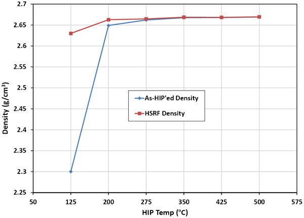
Density of as HIPed and forged plates versus HIPing temperature
Because the solidus for conventional AA 5083 is 574°C, 19 one can rationalise from the data that a 4 h hold time at 200°C, or 0·56Tm, and a pressure of 103 MPa is sufficient to consolidate well degassed (defined herein as <30 ppm H), cryomilled AA 5083 powder. Other researchers have shown dependence on powder size and morphology, 3 and HIP processing maps have been reported. 4 However, there have been few reports of the effects of HIP process parameters for cryomilled materials. A review of published studies show that considerations for HIP processing maps include powder size distributions, HIPing temperature, hold time at temperature, ramp rates, and ramp sequence (pressure and temperature). Because this work is primarily concerned with the processing of billets with minimal grain growth and sufficient density to achieve desirable properties after secondary processing (extrusion or forging), the HIP temperature study was limited to varying temperature during the 4 h hold time used in the HIP process. Powder size distribution was not explicitly studied, but starting powders before cryomilling were -325 mesh (<44 μm). Hold times were constant at 4 h, and ramp rates and sequences were all similar.
Figure 14 shows compression strength before and after annealing at 415°C, the recommended annealing temperature for AA 5083, 19 versus HIP temperature. Little variation is observed in the strength of the as HIPed billets, pointing to the likelihood that they were already well annealed after the HIP process. In contrast, the tensile strength of the HSRF plates before and after annealing show subtle but significant changes, as shown in Fig. 15. The plates showed little change in strength up to a HIP temperature of 500°C (MC 33), indicating the likelihood of more extensive grain growth than in samples HIPed below 450°C. This behaviour is consistent with the work of previous research by Tellkamp et al.,7,20 where they showed greater thermal stability at temperatures below 450°C. In the next section, where forging parameters are discussed, microstructural relationships – particularly grain size versus strength – will be explained. No grain size measurements are reported for the materials HIPed at different temperatures.
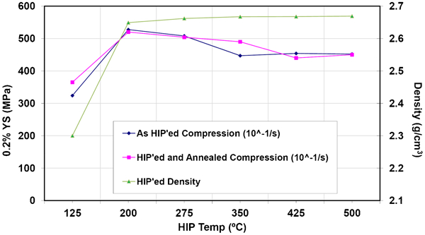
Compressive yield strength of as HIPed billets before and after annealing, shown with density and HIP temperature of billets
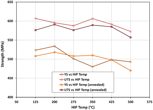
Tensile strength before and after annealing of HSRF plates, shown with density and HIP temperature of precursor billets
Forging parameters and Hall–Petch behaviour
The four densest plates, MCs 34 (275°C), 32 (350°C), 37 (425°C) and 33 (500°C), were analysed by TEM to determine grain size after the HSRF step, as shown in Figs. 6–9. Grain size was weakly dependent on HIP temperature. The nature of the grain size distributions hints that well distributed PPBs play a role in grain growth during the secondary processing step, where the lack of a well defined nascent oxide layer facilitates further grain growth.
16
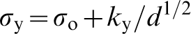
Using the grain size data tabulated in Table 3 and the yield strength data tabulated in Table 5, a plot of yield strength versus grain size was constructed, as shown in Fig. 16. From these plots, we determine the Hall–Petch coefficient for the four plates using equation (1), where σYS is the yield strength, σO is the intrinsic strength, ky is the Hall–Petch coefficient, and d is the average grain size21–23
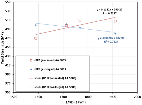
Hall–Petch plot for HSRF plates MCs 34, 32, 37 and 33, forged at 400°C, after HIPing at 275, 350, 425 and 500°C respectively: data plotted use YS values before and after annealing at 415°C for 30 min
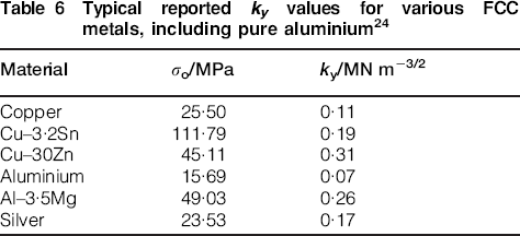
Typical reported ky values for various FCC metals, including pure aluminium 24
Other strengthening mechanisms
The discussion of strengthening in cryomilled AA 5083 should consider other mechanisms active in this system. While not the primary focus of this work, we recognise that AA 5083 in the HSRF condition may exhibit additional strengthening effects of solid solution, dislocation and Orowan mechanisms. Such additive effectives have been analysed in previous reports, where the authors showed plausible agreement between predicted and measured strengths.26,27 In those works, equation (2) was used, where σHP was defined in equation (1), σSS is the solid solution strength, σρ is the dislocation strengthening and sigma or σOR is the Orowan contribution.

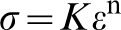
Given the composition and UFG nature of these materials, one can rationalise that dislocation plasticity is significant if not dominant during deformation, since all these mechanisms have been shown to contribute to strengthening. However, it becomes apparent through analysis of the work hardening regime of the true stress strain curves that the UFG materials differ greatly from the conventional, CG AA 5083 with regards to dislocation accommodation. In Fig. 17, two parallel methods of quantifying strain hardening are presented to portray this difference. First, a more traditional method of mathematically fitting data in the plastic regime,
23
before the UTS, was used to develop the strain hardening exponent n in equation (3)
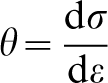
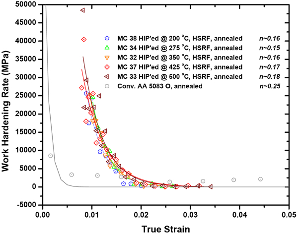
Correlation of work hardening rate θ to true plastic strain, with corresponding strain hardening coefficients n for annealed samples
Conclusions
While complete HIP processing maps may be available for several PM systems, access to these parameters is somewhat limited in the open literature. Moreover, such processing maps do not exist for cryomilled Al alloys. To address these questions, we have consolidated cryomilled AA 5083 by HIPing at six temperatures, followed by high strain rate forging. From our analysis of the experiments, we draw the following conclusions.
Near full theoretical density (when compared to conventional AA 5083) can be achieved by HIPing at temperatures as low as 200°C with a 4 h hold at temperature, but density further increases at HIP temperatures of 275°C.
After HSRF, the density of all plates HIPed at 200°C and above is greater than the theoretical density for conventional AA 5083. The elevated density values are attributed to dispersed oxides in the PM system, since porosity is still present.
Except for the plate produced from material HIPed at 125°C, all plates showed superior strength and ductility, almost twice the UTS of conventional AA 5083 H131, with similar ductility.
Because of the negligible differences in grain size and apparent porosity, there is no benefit to HIPing 8 h cryomilled AA 5083 at temperatures below ∼275°C for 4 h.
Increased grain growth and subsequent loss of strength is associated with HIP temperatures greater than ∼425°C.
Using the HSRF technique at 400°C is an effective means of secondary consolidation, where a desirable balance of strength and ductility can be achieved using billets consolidated by HIP.
Strengthening in these systems is attributable to the combined effects of Hall–Petch, solid solution, Orowan and dislocation mechanisms.
Work hardening in the UFG plates is more closely related to HSLA steel than aluminium.
Footnotes
Acknowledgements
The authors gratefully acknowledge: The Office of Naval Research (ONR N00014-12-C-0241) for funding to produce and characterise the materials with the assistance of Dr Piers Newbery; The Materials Design Institute, a joint research program between Los Alamos National Laboratory, LLC (LANS) and the College of Engineering, University of California, Davis (LANS Subcontract 25110-002-06) for funding to continue basic scientific research on the materials after they were produced; Joe Giglio and Tim Delahanty of Pittsburgh Materials Technology, Inc. (Jefferson Hills, PA, USA) for their expertise and assistance with Dynapak forging; Mark R. van den Bergh and Cory A. Smith of DWA Aluminum Composites (Chatsworth, CA, USA) for their technical expertise and manufacturing assistance during cryomilling.