
Abstract
Magnetic properties of Fe based composite materials with different particle sizes under a cryogenic condition have been investigated. Realisation of this venture has been carried out at the liquid nitrogen temperature. Results of energy loss density were obtained from measurements of the static (dc) hysteresis cycles ranging from 0·1 to 1·0 T. In turn, results of power loss density were obtained from measurements of the dynamic (ac) hysteresis cycles ranging from 50 to 1000 Hz and at the maximum flux density of 0·5, 0·8 and 1·0 T. The study confirmed the influence of temperature on magnetic parameters. It has been shown that total power loss density has increased with decreasing temperature. We report changes in a nature of energy loss after immersing specimens made of soft magnetic composites in liquid nitrogen. Measurements of the maximum relative permeability were also conducted.
Introduction
Powder metallurgy has recently gained an interest in the scientific and engineering community interested in the development of electric machines. This fact is closely related to possibilities for applications of parts made of powder in electric devices. Furthermore, powder metallurgy is characterised by low production cost, low waste of powder and easy recycling. There are two basic techniques for preparation of magnetic elements made of powders: sintering and bonding by a dielectric agent.1–3 Sintered parts have low resistivity; therefore, they are used only in devices with constant or low frequency magnetic fields. On the other hand, magnetic composites compared with sintered elements achieve a lower magnetic flux density; however, owing to their relative high resistivity, they are applied in devices with a power and higher frequency about up to 100 kHz.
In particular, the second technique is increasingly often applied in electromagnetic devices because of its advantages. Fe based composite materials, also called soft magnetic composites (SMCs), made of powder are more likely to be used in industrial electric devices. In many applications, magnetic circuits made of electrical steel can be successfully replaced by circuits made of powder. Powders used in compression moulding techniques are produced by mainly atomisation techniques; a liquefied metal is atomised by inert gas or water under high pressure, which leads to the creation of small liquid metal droplets that, after solidifying, become powder particles.
The expanding interest in the introduction of Fe based composite materials in electrical devices, such as electrical motors, is in obvious ways connected with their properties. The main feature of these materials is that iron particles are insulated by a thin organic or inorganic coating. SMCs offer several advantages over laminated steel sheet, e.g. isotropic magnetic properties, the opportunity to tailor their physical properties to requirements, very low eddy current loss, relatively high resistivity and high magnetic permeability.4,5
Fe based composite materials are used in manufacturing of electrical devices owing to their physical properties. The most common use of these materials is in various electric motors, e.g. a high speed permanent magnet motor, a synchronous electric motor, an axial flux permanent magnet synchronous machine and a claw pole permanent magnet motor. Furthermore, soft magnetic composites are used in an electromagnetic actuator and in electromagnetic shielding.6–11
The introduction of electrical devices in new branches of industrial applications, such as electric motors or actuators, is in obvious ways closely connected with possibilities offered by magnetic materials. For this reason, the design process of new devices should take into account the knowledge of material parameters. It is even more relevant when a device is designed for special applications.
Many authors focus on devices intended to work at cryogenic temperatures. Usually, these devices are motors submerged in a liquefied medium or motors with cryogenic cooling system. One of the basic applications of these motors is driving a cargo pump for unloading liquefied natural gas. Moreover, a research of induction generators operating in cryogenic environment has been conducted.12,13 A surge of interest has been observed in permanent magnet motors applicable in propulsion systems of fuel pumps in spacecraft, operating in cryogenic environments. 14
Results presented by Marignetti 15 illustrate the potential and the convenience of copper wound electrical machines with liquid nitrogen cooling. Cryogenic copper wound electrical machines use less copper to carry the same current compared to air or water cooled machines, thereby improving the power/weight ratio.
On the other hand, Marignetti et al. 16 describe the experiments carried out on a short stroke tubular linear permanent magnet machine with copper windings and liquid nitrogen cooling.
Abe et al. 17 report the basic characteristics of a linear oscillatory actuator for liquid hydrogen pump. In turn, Aoki et al. 18 present the static thrust characteristics of a linear oscillatory actuator at low and room temperatures; as shown, the detent force at low temperature was larger than that at room temperature. Another example of electric machine that can be used to produce motion at low temperature is a miniature dc motor. 19 The motor is a skew wound ironless device with a coaxial gearhead and is capable of operating at a temperature of 4 K in a vacuum.
To date, magnetic properties of Fe based composites operating at cryogenic temperatures have not been measured. This fact has prompted the authors to determine magnetic properties of SMC materials under cryogenic conditions. It seems that the results of such research will be very useful for designers of electric machines considering the growing interest in cryogenic magnetic composite applications. For this reason, research has been conducted on these materials working in liquid nitrogen atmosphere with temperature of 77 K.
Experimental
Specimens investigated in this study were produced from commercially available iron powders produced by water atomisation techniques, with a special surface coating on each and every particle. The Fe powder particles are distributed in dielectric matrix that simultaneously plays a role of adhesive agent. The first powder used in the investigation was AncorLam produced by Hoeganaes Corporation, and the second powder was Somaloy 700 produced by Höganäs AB Company.
Specimens made of both powders were produced by cold pressing under pressure of 800 MPa. The specimens made of AncorLam powder were cured at a temperature of 455°C for 30 min in air, whereas the specimens made of Somaloy 700 powder were cured at a temperature of 530°C for 30 min in air.
The compaction pressure and the temperature of curing were applied in accordance with the manufacturer's recommendations. The specimens used in the experiments were ring shaped with a square cross-section. The specimens had the following dimensions: external diameter of 55 mm, internal diameter of 45 mm and thickness of 5 mm (Fig. 1).
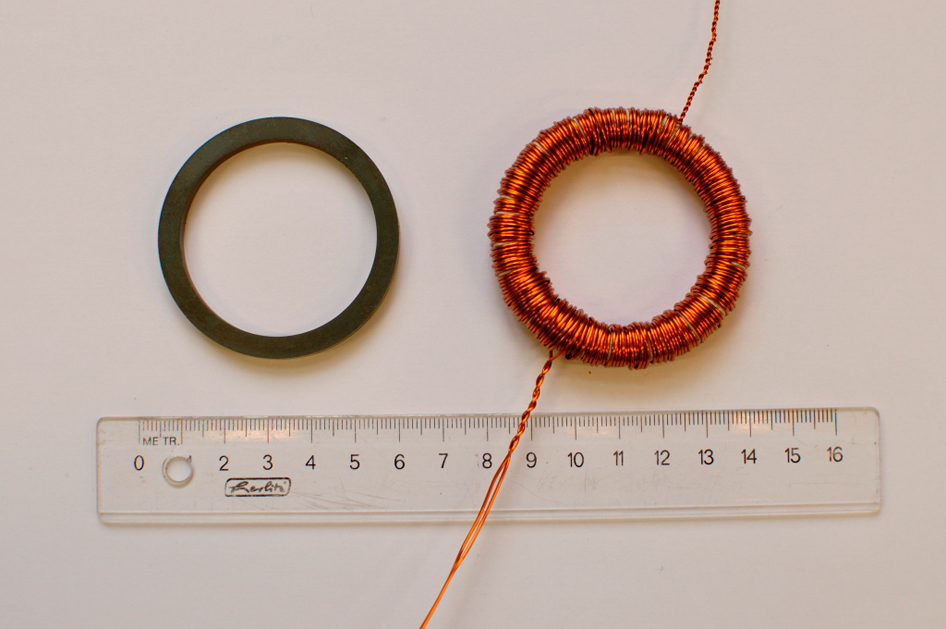
Optical image of ring shaped specimens
The energy loss (volume) density w, an area of hysteresis cycle, expressed in joules per cubic metre (J m−3), was obtained from measurements of the dc hysteresis cycle according to the IEC Standards 60404-4 using hysteresisgraph AMH-20K-HS produced by Laboratorio Elettrofisico Walker LDJ Scientific. The magnetic energy losses were measured at maximum flux density Bm = 0·1,…,1·0 T. Measurements of power losses and magnetic energy losses were conducted by recording individual points and the integration of area of the hysteresis loop.
Total power loss density Ptot, expressed in watts per kilogram (W kg−1), was obtained from measurements of the ac hysteresis cycle according to the IEC Standards 60404-6 using the same hysteresisgraph. Total power losses Ptot were measured at maximum flux density Bm = (0·5, 0·8, 1·0 T) over a frequency range from 50 to 1000 Hz. During measurements of the total power losses Ptot, the shape factor of the secondary voltage was equal to 1·111±1·5%. Maximum measurement error of the total energy losses was equal to 3%.
The first series of measurements were conducted at room temperature, and then the same specimens were immersed in liquid nitrogen.
The particle morphology observations were carried out using a scanning electron microscope JSM-7600F produced by JOEL. The particle size distributions were obtained using the laser scattering particle size distribution analyser LA-950 produced by Horiba.
The parameters of energy loss model have been estimated for each specimen's measurement data using non-linear least square minimisation technique.
Results and discussion
Powder and composite properties
Results of measurements of the particle size distributions of both powders are shown in Figs. 2 and 3. The mean size of AncorLam powder is ∼166 μm and most particles (90%) are <275 μm, while in the case of Somaloy 700, the mean size is ∼293 μm and most particles are <462 μm. The standard deviations of the particle size distribution are 85 and 133 μm respectively for AncorLam and Somaloy 700 powders.
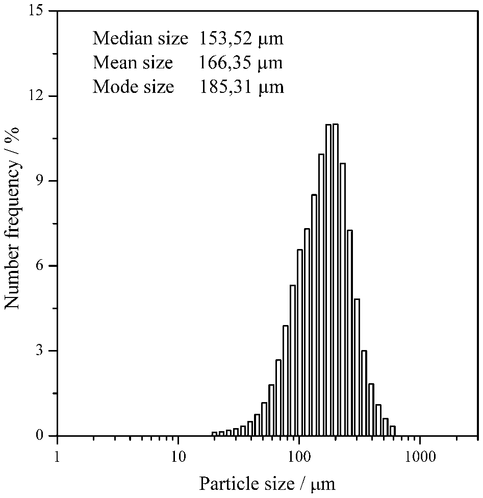
Particle size distribution of AncorLam powder
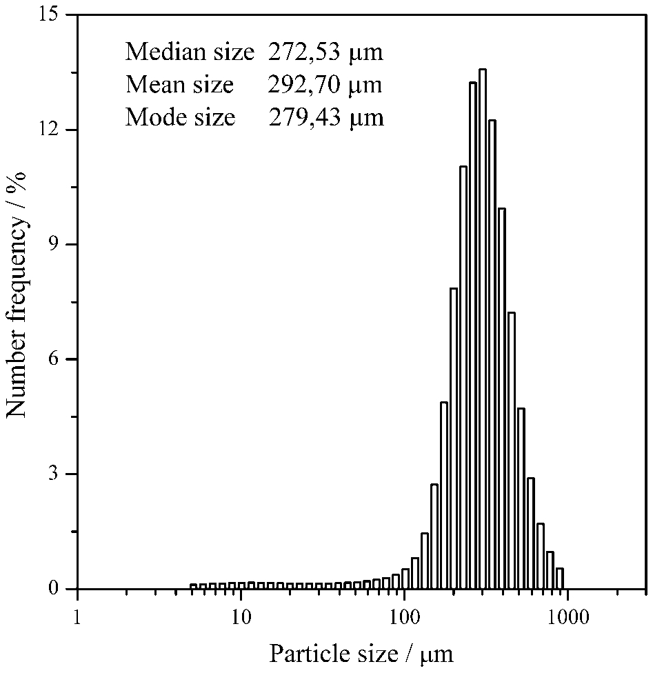
Particle size distribution of Somaloy 700 powder
Figures 4 and 5 show the particles of both powders. As can be seen in the figures, particles of both powders are very irregular in shape. The investigation conducted using a scanning electron microscope confirms the differences in particle size.
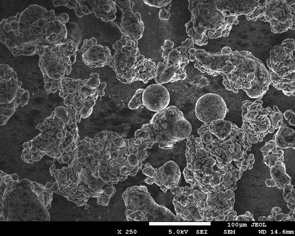
Particles of AncorLam powder
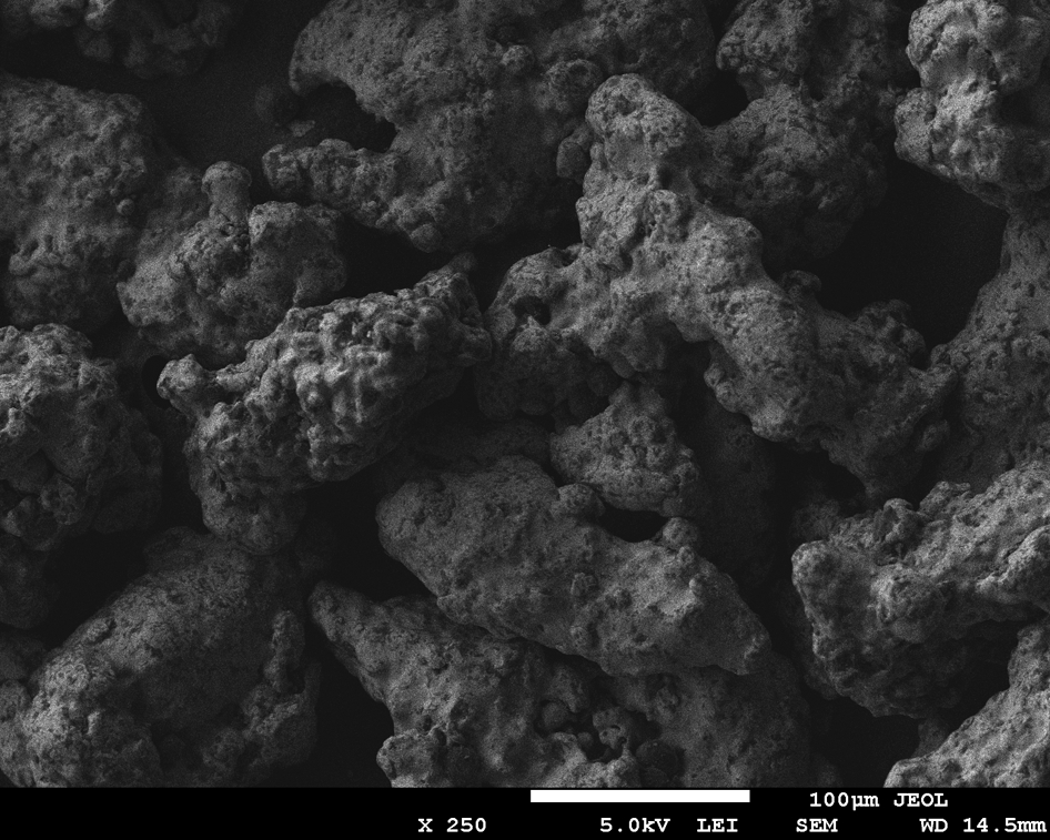
Particles of Somaloy 700 powder
The density of the specimen made of AncorLam powder was equal to 7·34 and 7·41 g cm−3 for the specimen made of Somaloy 700 powder
Direct current hysteresis cycle
Measurements of the static hysteresis loop have been taken to show how the ambient temperature influences the magnetisation process. First, the static hysteresis loops have been measured at room temperature, and then the same specimens were used in measurements at liquid nitrogen temperature and atmosphere. A comparison of measurements of the energy loss volume density w is depicted in Fig. 6. The significant increase in the energy loss results from the change of the ambient temperature. This effect is observed in both materials. Lowering of the temperature leads to a reduction of atom vibrations in crystal lattice; thus, the scope of movements of domain walls is limited. The magnetocrystalline anisotropy will increase at lower temperatures, meaning, that a higher field is needed to reach a given magnetisation level. A consequence of this phenomenon is an increase in magnetisation energy losses.
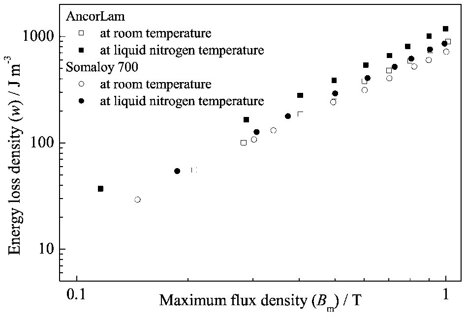
Comparison of energy loss density w as function of induction B for specimens made of AncorLam and Somaloy 700 powders, measured at room and liquid nitrogen temperature, measured at dc
However, it should be mentioned that magnetisation energy depends greatly on the domain structure. Materials with large particle size (>100 μm) have a complex structure of magnetic domains. The magnetisation process in these materials takes place through the motion of magnetic walls and rotation of the magnetisation vector. It is, however, dominated by the first component, which contributes to reduce the hysteresis loss. On the other hand, in the materials with a small size of particles (<100 μm), the rotation of the magnetisation vector plays a dominant role. 20 The studies conducted confirmed the relationship between particle size and magnetisation energy.
ac hysteresis cycle
Figures 7 and 8 show the total power loss density Ptot in different frequencies and at various inductions. The core losses increase monotonously with the increase in frequency for both types of magnetic composites. After immersion of the specimens in liquid nitrogen, the total power losses increase significantly. As has been shown, there are changes in total core losses as a result of the increase in magnetocrystalline anisotropy.
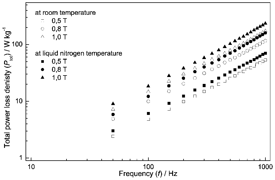
Comparison of total power loss density Ptot as function of frequency f for specimen made of AncorLam powder measured at room and liquid nitrogen temperature
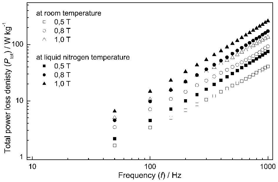
Comparison of total power loss density Ptot as function of frequency f for specimen made of Somaloy 700 powder measured at room and liquid nitrogen temperature
An additional factor affecting the core losses, important especially for high frequencies, is the eddy currents. In the instance of soft magnetic composites, the eddy currents can occur between neighbouring grains and intergrains. The occurrences of these currents cause additional core losses.
Comparison of an increase in the energy loss density before and after immersion in liquid nitrogen for measurements conducted on specimens made of different powders leads to the conclusion that a contribution of particular sources of energy dissipation is different. Considering changes at frequency of 50 Hz, we can notice that for specimens made of AncorLam powder, the energy loss density increases up to 21%; in turn, for specimens made of Somaloy 700 powder, this loss increases up 32%. By analysing an increase in the total energy loss, at frequency of 1 kHz, we can observe that this loss increases up to 37% for specimen made of AncorLam powder and almost twice for specimen made of Somaloy 700 powder.
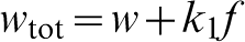
In order to identify mentioned changes of the total energy loss density, caused by different sources of energy dissipation, equation (1) has been used. As a result of such proceedings, the total energy loss density can be divided into two components. The first component determines content of hysteresis loss density, whereas the second component determines content of eddy current loss density
Computations conducted for specimens made of AncorLam powder, both at room temperature and at liquid nitrogen temperature (Fig. 9), and for specimens made of Somaloy 700, measurements at room temperature (Fig. 10), confirmed linear relationship of the total energy loss density wtot versus frequency f.
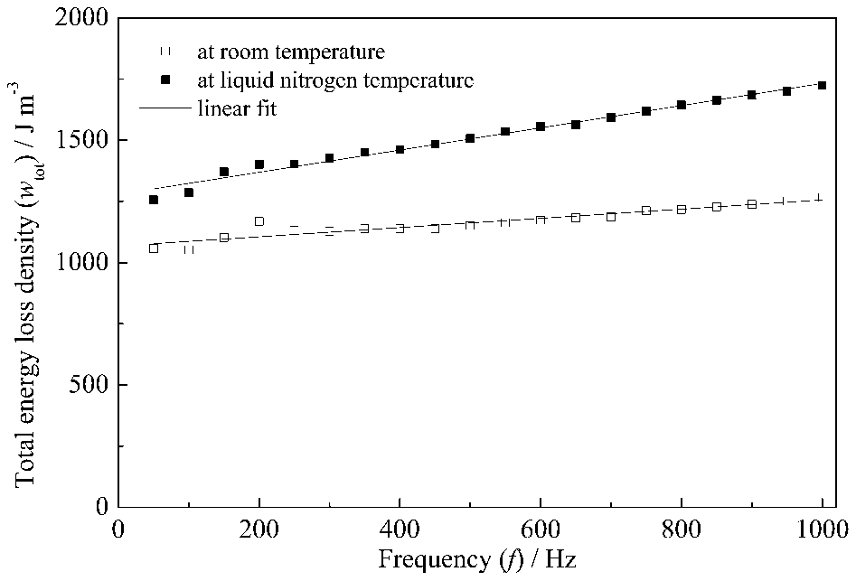
Comparison of total energy loss density wtot as function of frequency f for specimen made of AncorLam powder measured at room and liquid nitrogen temperature, at maximum induction Bm = 1·0 T
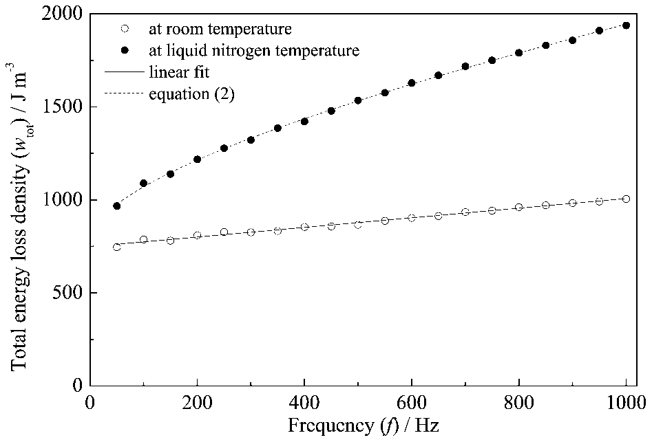
Comparison of total energy loss density wtot as function of frequency f for specimen made of Somaloy 700 powder measured at room and liquid nitrogen temperature, at maximum induction Bm = 1·0 T
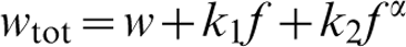
Measurements conducted for specimen made of Somaloy 700 (Fig. 10), at liquid nitrogen temperature, revealed non-linear relationship between wtot and f. Accordingly, application of extended equation (2) is necessary to correct description of the total energy loss density wtot. Therefore, an additional component of a power law with a fractional exponent α has been introduced into equation (1)
Estimated values of y intercept (Table 1), which correspond to the energy loss density w when f→0, are similar to the measured values shown in Fig. 6. Values of y intercept, furthermore, confirmed the fact that, in the case of low frequency, a powder with large particles is preferred to use.
Coefficients for total energy loss density model
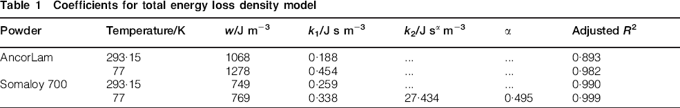
A dynamic component of the total energy loss density wtot in case of the composite made of AncorLam powder is proportional to frequency f, which is illustrated in Fig. 9. It can be assumed that we are dealing with the growth of classical eddy current loss.
At room temperature, the dynamic component of energy loss density in composite made of Somaloy 700 has the same nature as the composite made of AncorLam powder, i.e. it is linear function of frequency f. This component of energy loss density changes its character after immersing in liquid nitrogen. In addition to the growth of classical eddy current loss, there are also excess energy losses that are described by the third component of equation (2). It is worth noting that the value of exponent α = 0·495 is similar to the value presented by Bertotti et al.21,22
It is clear that magnetic composites with larger particle size have greater eddy current loss than those with a smaller particle size. This is in obvious ways connected with the depth of penetration (skin depth). In the case of larger particles, the magnetic field does not penetrate the whole volume, but only to the external layer. The skin effect causes the effective resistance of the conductor to increase at higher frequencies where the skin depth is smaller, thus reducing the effective cross-section of the conductor and the increase in energy losses.
Maximum relative permeability
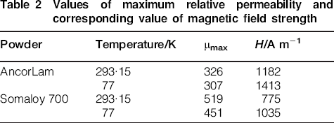
Lowering the temperature leads to changes in magnetic properties, i.e. power losses. One of the most important parameters is magnetic permeability, which depends on the ambient temperature. Measurements of the maximum relative permeability have been conducted at 50 Hz frequency. For specimen made of AncorLam powder, the maximum relative permeability decreased by ∼6%. In the case of specimen made of Somaloy 700, the maximum relative permeability decreased by ∼13%. The results are summarised in Table 2.
Values of maximum relative permeability and corresponding value of magnetic field strength
Conclusions
The investigation has been conducted in order to study the influence of temperature on magnetic parameters of composite materials. Lowering the temperature leads to an increase in the power losses and a decrease in the relative permeability. Furthermore, the influence of particle size on the magnetic parameters has been discussed. Particle size distribution is one of the most important factors that determine the physical properties of composite materials. In composite materials prepared from powders with a small grain size, the dominant kinds of losses are hysteresis losses. In the composite materials prepared from powders with a large grain size, the eddy current losses are revealed. It is also essential for the power losses in electromagnetic devices to adjust the grain size of powder materials to the operating frequency. Further work is to be conducted in order to confirm correlations between temperature and physical parameters of magnetic composite materials for materials with different particle structures from those already researched.