
Abstract
Additive manufacturing is a novel way of processing metallic cellular structures from a powder bed. However, differences in geometry have been observed between the CAD and the produced structures. Struts geometry has been analysed using X-ray microtomography. From the 3D images, a criterion of ‘mechanically efficient volume’ is defined for stiffness prediction. The variation of this criterion with process parameters, strut size and orientation has been studied. The effective stiffness of struts is computed by finite element analysis on the images obtained by X-ray tomography. Comparison between the predicted stiffness and the effective one tends to show that the efficient volume ratio leads to a slight underestimation of the stiffness. Finally, the effective stiffness is used at the scale of a unit cell. This can help define the build orientation and loading direction that lead to the highest stiffness.
Keywords
Introduction
Bulk titanium alloys exhibit high mechanical properties for a relatively low density (∼4·5 g cm−3). They find their main applications in aeronautics as structural parts such as airframe fittings, brackets or landing gear structures. The recent change from bulk parts to cellular structures brought a breakthrough in designing structural parts. The idea of creating architectured materials came as the necessity to fill holes in materials space.1–3 Cellular structures are indeed a particularly well adapted answer for multifunctional requirements. This is done by combining the advantages of light weight and functional or structural performances. Applications of such structures have grown in the recent past, ranging for instance from energy absorptions, 4 heat transfer or sound barrier.
The identification of the parameters controlling the properties of architectured materials remains an open question. Gibson and Ashby 5 were the first to propose analytical scaling laws for the variation of the effective stiffness with the relative density of cellular structures. Depending on the nature of the porosity (open or closed), depending on the struts, faces and vertices connectivity, they predicted pre-factor and exponent values of these scaling laws. Combining the properties of such structures with the bulk properties of titanium alloys should allow high stiffness (or strength)-to-density ratios.
Manufacturing titanium cellular structures has been a challenge over the years. Traditionally, titanium foams have been produced by powder sintering processes or solid state foaming 6 without reaching a high level of porosity. The recent development of additive manufacturing of metallic parts allows the possibility of creating materials without significant limitations of design due to the process. In particular, cellular structures can be manufactured directly from a 3D optimised CAD. Various techniques have emerged, depending on the selected heating source (i.e. laser or electron beam). In this work, the selected additive manufacturing technique is electron beam melting (EBM). Regarding this technique, cellular structures in titanium alloys have already been manufactured and mechanically characterised.7–9 In particular, new auxetic structures (i.e. exhibiting negative Poisson's ratio) have been recently proposed and manufactured.10–12
The present work consists in manufacturing cellular structures by EBM and focusing the structural characterisation at the scale of a single strut. The aim is to predict the stiffness of the global structure, taking into account the ‘imperfections’ detected at this scale. Only geometrical imperfections are addressed. They are assumed to be of first order compared to microstructural aspects at least for the stiffness of the thin cellular structures studied here. The differences between the initially optimised CAD and the real part are highlighted. Struts with different orientations (relative to the build direction) are characterised in 3D using X-ray micro-tomography. The repartition of matter throughout the strut is then identified. A criterion of minimum stiffness is suggested by discriminating the inefficient volume. The variation of this criterion with strut size and process parameters is identified. A refinement of this criterion is proposed to predict the effective stiffness of an octet-truss structure and its behaviour depending on build orientation and loading direction.
Methods and experiment
Electron beam melting
The cellular structures have been manufactured layer by layer using the EBM device. After designing the 3D CAD, the volume is sliced in 50 μm layers. The process consists in an electron beam that selectively melts 50 μm of powder at each layer according to the sliced CAD (Fig. 1). The powder is held in two hoppers and a rake allows the powder repartition at each layer.
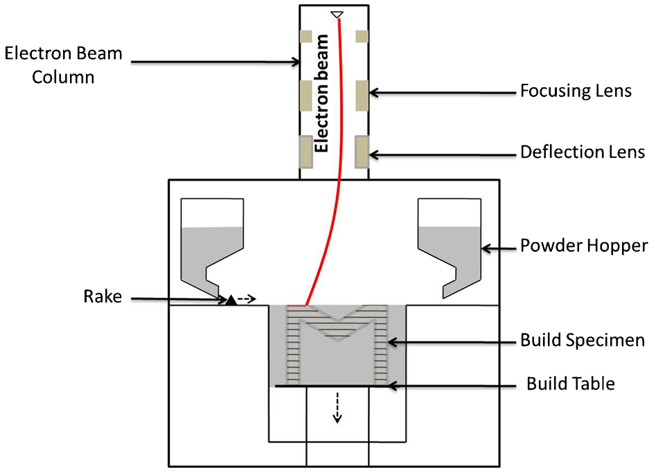
Scheme of electron beam melting process
The electro-magnetic deflection lenses allow the beam scan speed to reach 8000 m s−1 thus, allowing a high build rate. During the process, the build chamber is held under vacuum at 10−5 mbar and each layer is heated to 750°C for a pre-sintering of the powder bed. This step helps to increase the effective thermal and electric conductivity of the global powder bed as well as controlling the final microstructure of the built parts. At the end of the process, the block of pre-sintered powder containing the melted parts is removed from the machine and blasted for breaking necks between particles. The non-melted powder is then re-used after a step of sieving.
The system used for this work is an A1 ARCAM machine with a maximum build envelope of 210×210×180 mm and a power varying between 50 and 3000 W.
Powder characterisation
For this work, a standard gas atomised Ti–6Al–4V powder is used, provided by ARCAM. Figure 2 shows the particle size distribution of the titanium powder obtained using a Mastersize 3000 laser particle size analyser.
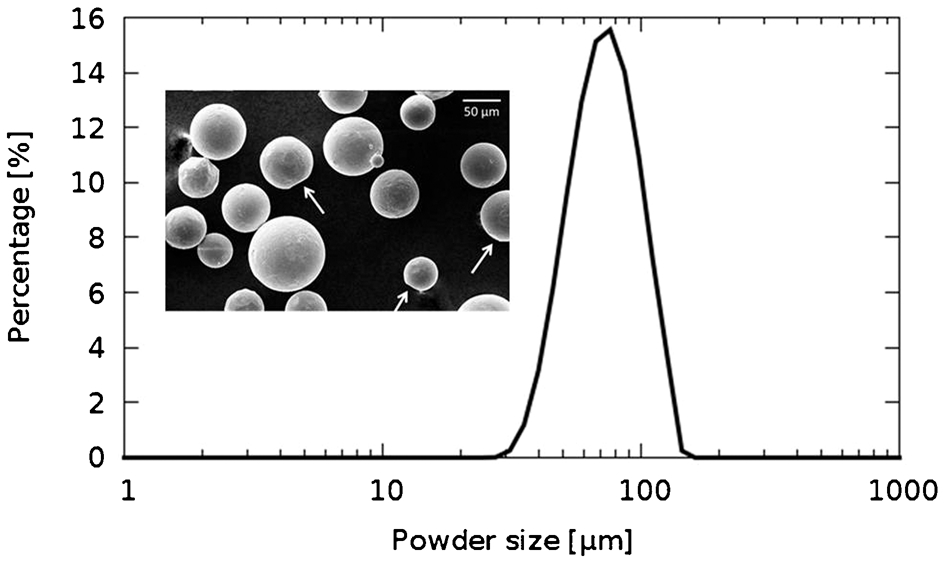
Ti–6Al–4V powder laser granulometry and SEM image of titanium powder
The powder has a relatively narrow size distribution with a median diameter of 77 μm. Ten per cent of the particles have a diameter lower than 50 μm and 90% have a diameter lower than 113 μm. This range of particle size is chosen by the supplier to prevent any explosition.
The SEM micrograph in Fig. 2 shows the shape of the powder. Particles made by gas atomisation are spherical although they exhibit small facets (white arrows) which are a trace of the previous necks coming from previous sintering of these particles.
X-ray tomography and FEM simulation
Post-mortem X-ray tomography has been carried out on different struts with a voxel size varying between 1·1 and 2·5 μm3. For each experiment, a strut was analysed over roughly 2 mm in height. A typical image of a strut is shown in Fig. 3.
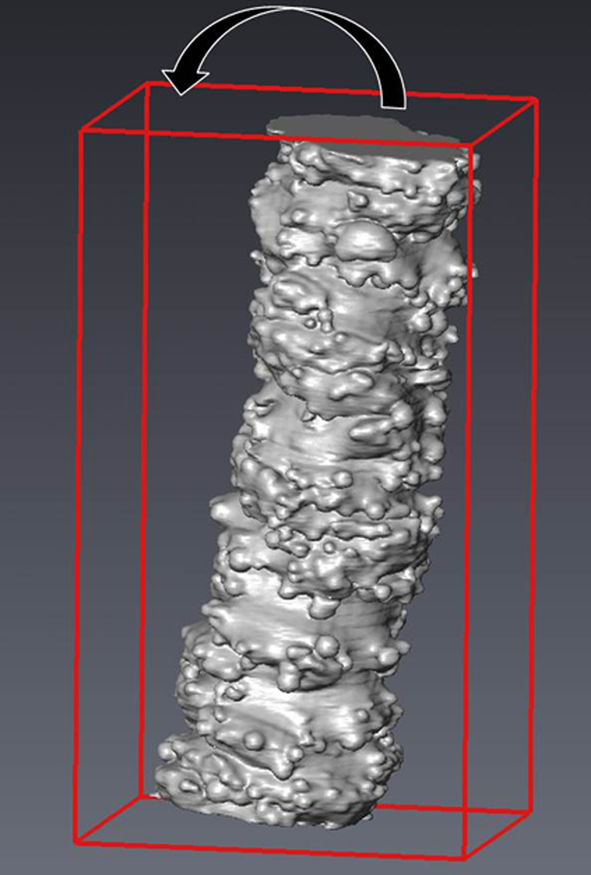
3D image of 1 mm diameter strut. Scale: 50 pix = 125 μm
Images are binarised using the software ImageJ. Due to the orientation during tomography experiments, struts are not fully aligned to the z direction of the stack. Images have to be tilted by an iterative technique to fully align the neutral fibre of the strut in the z direction of the image.
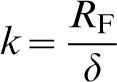
The volume is then meshed using Avizo, a 3D image analysis software. Then, the meshed volume is imported into a standard finite element software (Comsol) for stiffness calculation. An axial displacement δ is imposed at the top of the strut whereas the bottom is fixed. The strut's stiffness is deduced from the reaction force Rf in the loading direction
a global octet-truss unit cell; b 3D reconstruction of one strut; c isometric view showing fully dense strut
Results and discussion
Efficient volume ratio analysis
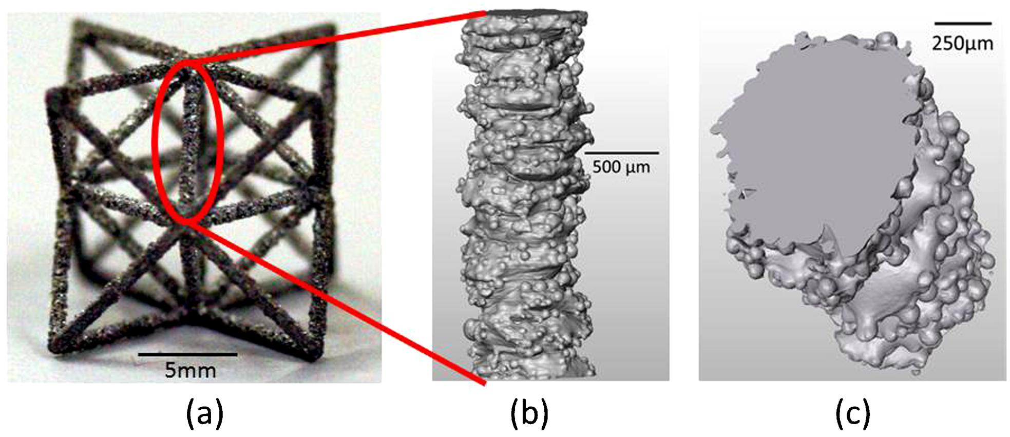
The 3D images enable the inner and outer characterisation of struts. In Fig. 4a–c, a strut of 1 mm of diameter is shown at three different scales. This strut is part of an octet-truss elementary cell (Fig. 4a). Closed porosity is investigated throughout the strut. As it can be seen in Fig. 4c, it is really low (at least for the resolution used). Depending on the orientation of the strut and the process parameters it could fluctuate, but always remaining lower than 0·1%. In the following, struts will be considered as fully dense.
As Fig. 4b shows, the surface roughness of a strut is partly due to the unmelted powders that stick to the melt pool. Most of the roughness comes from the melt pool itself which is quite broad leading to this ‘plate-pile’ like structure. The corrugation of the roughness is randomly oriented with a period in z of about 50 μm. It is linked to the slicing and building increment. Knowing that, one can expect that a part of matter does not contribute to the stiffness of the strut. From the 3D volume, it is possible to extract two geometries to help predicting the stiffness of one strut and by extrapolation, the stiffness of a global cellular structure.
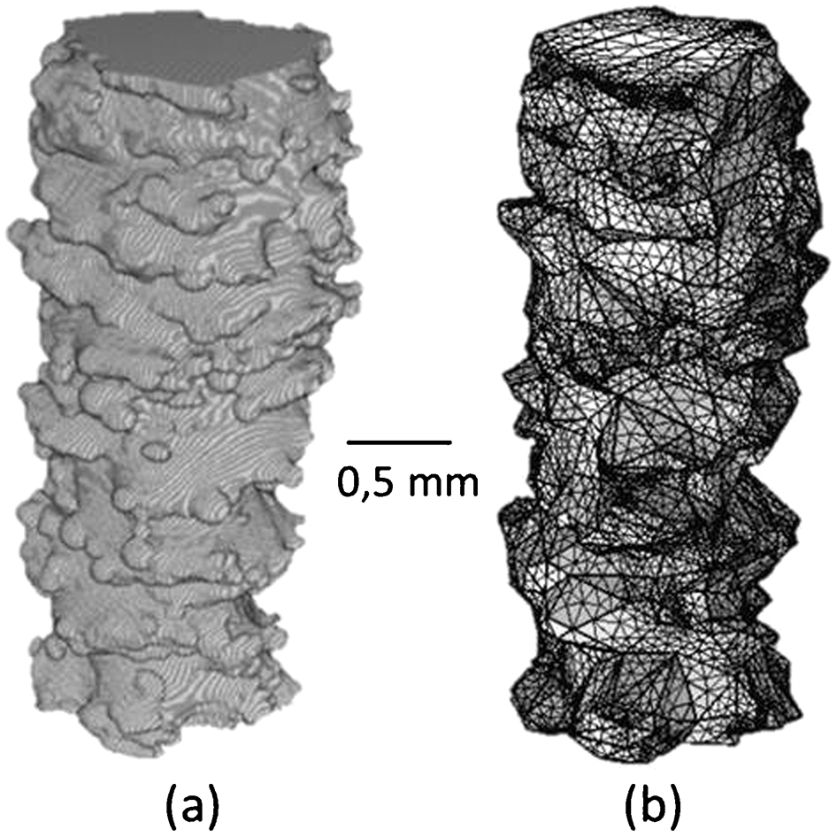
As shown in Fig. 5a, an inscribed surface is suggested to represent the minimum stiffness prediction of the strut whereas the circumscribed one lead to an upper bound. The inscribed surface is obtained by doing a projection of every stack in the z direction and keeping the pixels that are inside the strut for every stack. A cylinder can be extracted from this inscribed surface (in red in Fig. 5b). Similarly, the circumscribed surface can also be obtained with the same technique but keeping the pixels that are inside the strut at least in one stack.
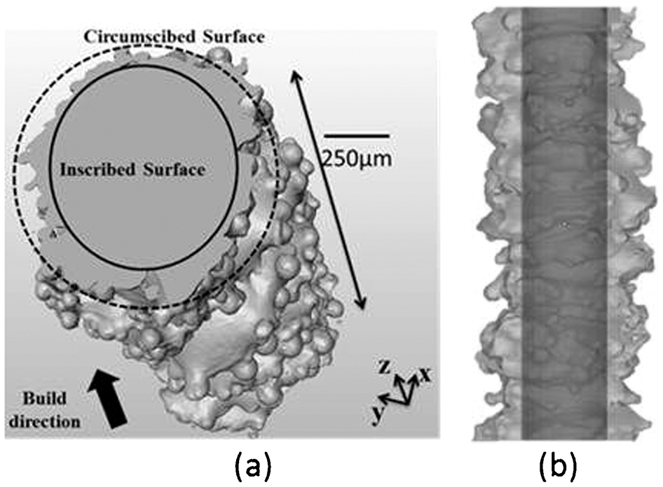
a tomographic reconstruction of a 1 mm strut with the parameters of inscribed and circumscribed surface and b reconstruction of inscribed cylinder (dark) inside the real strut (light)
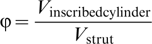
In the present study, an efficient volume ratio Φ is defined as the ratio of volume of the inscribed cylinder volume over the volume of the strut estimated from 3D image analysis
Influence of strut orientation (for given strut diameter and process parameters)
Shape and properties of bulk parts fabricated by EBM can be dependent upon their orientation in respect to the build direction. The same trend is also expected for cellular structures. In the present study, three fabrication orientations have been investigated: vertical, horizontal and at 45°. Each strut has the same CAD diameter and the same standard process parameters as defined by ARCAM. The efficient volume ratio for a 1 mm strut is 47, 36 and 37% respectively for vertical, horizontal and 45° oriented struts.
A higher efficient volume ratio is obtained for the strut built vertically rather than horizontally. Horizontally-built struts display an elongated shape in their radial direction due to the fact that they are built on top of powder which has lower thermal and electrical conductivities. As a result, the strut undergoes a stronger melting, creating a deeper melt pool. The melt pool is consequently less controlled, resulting in higher open porosity and roughness due to powder sticking. Built struts (45°) exhibit almost the same trend as horizontal ones because it has similar issues of over-melting for its down-facing side.
Influence of strut diameter (for given orientation and process parameters)
To study the influence of strut diameter on the efficient volume ratio, various vertically-built struts have been fabricated using a standard theme for each range of diameter. Each set of parameters (defined by ARCAM) produces fully dense struts in their range of application. Results are presented in Fig. 6. For struts with diameter larger than 2 mm, the efficient volume represents more than 80%. It becomes critical for strut sizes reaching the machine resolution limit of 0·4 mm.
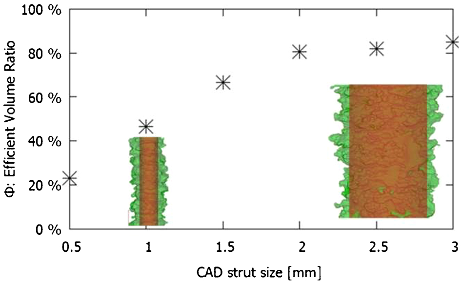
Variation of Φ with strut size for vertical strut and standard set of process parameters
Influence of process parameters (for given strut diameter and orientation)
For a given orientation and size, another way of optimising the efficient volume ratio is to tune process parameters. Different struts with a diameter of 1 mm oriented at 45° have been created with various energy densities. By changing the beam intensity, focalisation or deflection speed, it is possible to change the energy density brought to the system. For one layer, the energy density is defined by the energy divided by the surface of the beam path
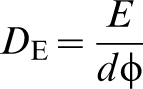
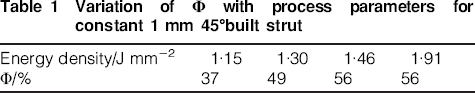
Results are presented in Table 1. In this range of energy density, increasing the energy density brought to the system increases the efficient volume ratio.
Variation of Φ with process parameters for constant 1 mm 45°built strut
The efficient volume ratio can be used as a correction factor for an analytical stiffness value. Knowing the unit cell geometry, it is possible to predict its stiffness by applying this criterion depending on the struts orientation and size. It is for sure the lowest stiffness that the structure can exhibit.
Refinement by FEM calculations
To refine this prediction, 3D volumes of 1 mm strut are meshed using Avizo. After meshing the strut surface, a step of mesh simplification has to be carried out to make the meshed volume easier to import into the FE software (Fig. 7). This quite tedious and somehow empirical procedure leads to a loss of details in the description of the strut, but keeps the major geometrical characteristics.
a voxelised volume; b meshed volume
The meshed volume is then compressed along its neutral fibre in the finite element software COMSOL, as explained in the section on ‘X-ray tomography and FEM simulation’. The stiffness of the strut is computed. Its value is reported in Fig. 8 which displays the stiffness of circular cylinders as a function of their diameter. This value corresponds to the one of a cylinder of diameter 0·62 mm, slightly greater than the diameter of the inscribed cylinder. The efficient volume ratio (defined from the inscribed cylinder) thus underestimates the stiffness of the strut. This difference is probably due to some radial forces that play a role even in the longitudinal stiffness of such struts.
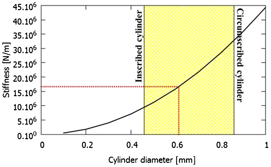
Stiffness variation with cylinder diameter for circular cylinders. Hatched zone: delimited between inscribed and circumscribed cylinders for 1 mm vertical strut. Dotted line: Stiffness of 3D meshed 1 mm vertical strut
The efficient volume ratio is rather easy to calculate and does not need time-consuming meshing and mesh simplification steps. Therefore, as it underestimates the stiffness, Φ could be used for designing structure in a safety way.
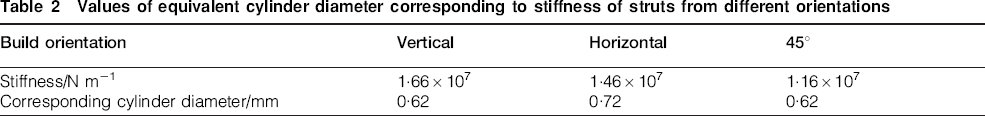
The same procedure has been applied to struts built at 45° and horizontally. Corresponding values of stiffness and corresponding cylinder diameter are reported in Table 2. It is then possible to simulate the effective Young's modulus of an octet-truss structure through its unit cell by defining different cylinder diameter of struts according to their orientation during the fabrication.
Values of equivalent cylinder diameter corresponding to stiffness of struts from different orientations
Two orientations of fabrication have been studied. Octet-truss built at 45° (Fig. 9a and b) are easier to take off from the build plate due to the smaller contact surface shared by the part and the build plate. In this configuration, six struts are built vertically, six horizontally and 24 at 45°. As a consequence, the structure could have different stiffness depending on the loading direction (as shown in Fig. 9b). It can be assumed that Z and Y directions are equivalent due to the repartition of vertical and horizontal struts within the structure.
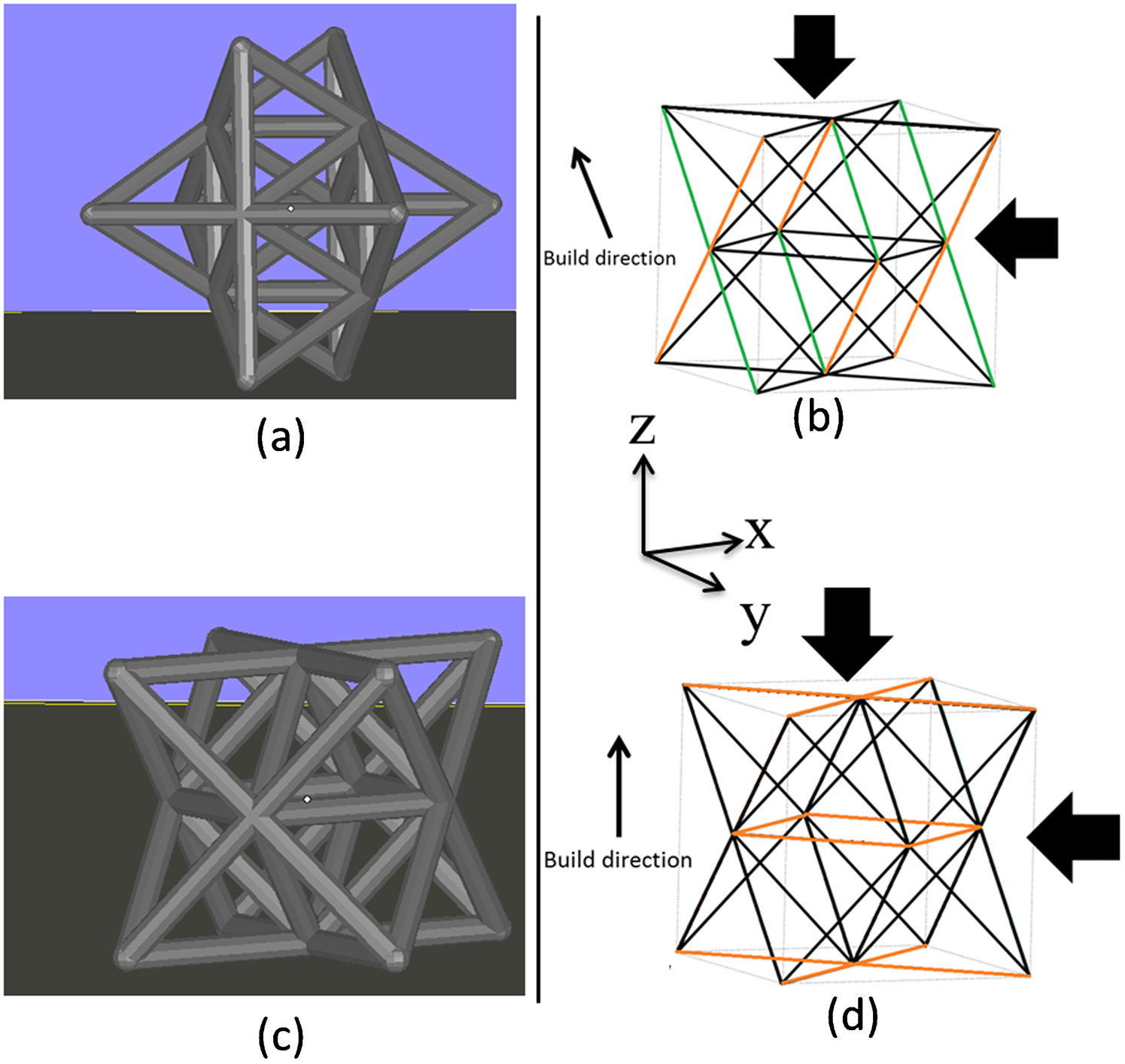
a as fabricated 45° octet-truss; b Z–Y and X loading for unit cell build at 45°; c as fabricated vertical octet-truss; d Z and X–Y loading for unit cell built vertically. Green/dotted lines: struts built vertically. Orange/grey: struts built horizontally
A unit cell built vertically (Fig. 9c and d) contains 12 struts built horizontally and 24 built at 45°. In this case, the X and Y loading directions are equivalent.
For a given relative density of 10%, the stiffness of each configuration has been computed in order to assess the configuration of maximum Young's modulus. Results show poor variation with the loading direction for each configuration. According to the simulation, the configuration of maximum Young's modulus is for a structure built vertically with a loading in the X or Y direction. It is 5% stiffer than any loading for a 45° built octet-truss.
Although the difference between the extreme configurations is limited in this case (less than about 5%), the whole procedure remains interesting for stiffness prediction of any cellular structure fabricated by EBM.
Conclusions
This work suggests a procedure for stiffness prediction of cellular structures manufactured by additive manufacturing. Due to the ‘electron beam melting’ process, a difference of geometry between the desired and the real struts is observed using high resolution X-ray tomography. By discriminating the mechanically used and unused matter, it is possible to predict the stiffness of one strut depending on its orientation, CAD size and process parameters.
A criterion of ‘efficient volume ratio’ is defined. This criterion gives a lower bound of the stiffness. To refine this criterion, the voxelised volume has been meshed for its stiffness measurement using a standard FEA software. Although this step is time-consuming, it allows to access the effective stiffness of the struts.
A circular cylinder having the same stiffness as the real strut is used for stiffness prediction of global structures such as octet-truss. Using this procedure, a 5% difference of Young's modulus has been shown between different build orientations and loading directions.
The procedure presented here tends to highlight the possible difference of stiffness between a desired geometry and the manufactured one. Designers would have to use the efficient volume ratio for stiffness prediction as it includes a safety coefficient for the structure.
Mechanical testing of octet-truss structures will be carried out for comparison with the predicted stiffness. To fully understand the discrepancies between CAD and produced parts, microstructural characterisation of struts will be carried out on different orientations and sizes of struts.
Footnotes
Acknowledgements
The authors would like to thank Luc Salvo for his help in the X-ray tomography experiments at ESRF (ID15 and ID19 lines, Grenoble, France) and Jérome Adrien for his help in the X-ray tomography at INSA Lyon (Lyon, France). They also gratefully acknowledge the support of Grenoble Institute of Technology for its SEI funding.