
Abstract
The laser metal deposition process is characterised by the occurrence of mutually influencing phenomena. Particularly important for understanding particle deposition are the phenomena originated by the three-way interaction of the laser beam, the powder stream and the substrate, which in previous models have been consistently oversimplified or neglected. This work presents a numerical model useful for studying powder stream formation, powder heating and mass addition into the melt pool, as well as various interactions that occur during processing. Experimental work is performed to validate powder stream formation and heating, and particle addition to melt pool. Good agreement is found with the modelled results. It is revealed from this work that the role of the substrate is more significant than previously thought and that considering the beam–stream–substrate interrelations allows simulations closer to real processing conditions to be performed.
Introduction
Laser metal deposition is a rapid prototyping and manufacturing process that combines technologies such as lasers equipment, motion control systems and powder metallurgy. It has been used for applications ranging from repair of components for the aerospace industry, deposition of dissimilar materials,1 to the manufacture of customised implants for the biomedical sector. Figure 1 represents the typical configuration of a cladding system using a nozzle coaxially aligned to the laser beam. The process is characterised by a complex combination of physical phenomena, which as represented in Fig. 2, can be described as: motion of the powder stream caused by the influence of surrounding gas as well as trajectory deflection caused by collision with nozzle walls, powder heating caused by interaction between the in-flight particles and the laser beam, heat transfer from powder particles to the surrounding environment, and influence of the substrate on particle catchment.
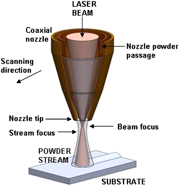
Scheme of a standard laser deposition system
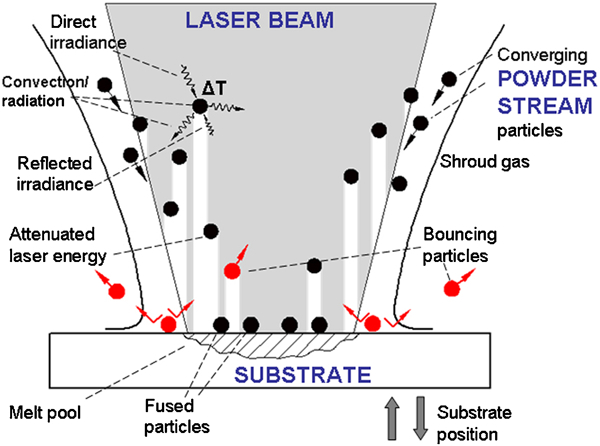
Map of phenomena that occur during deposition
Studying these phenomena is a complex task to achieve using experimentation alone due to the difficulty of measuring the very high energy intensities associated with the laser beam incident on a small processing area, while also dealing with the high velocities at which powder particles are travelling. Hence, simulation becomes a more suitable tool for a detailed study of the process. Lin and Steen2 used the FLUENT code to carry out some of the early works on numerical modelling of the powder stream from a coaxial nozzle, and thereafter, a number of models have been developed to deal with different aspects of the process using a variety of approaches. Pinkerton and Li3 developed a useful analytical model for studying the shape of the powder stream and the distribution of mass, using the geometrical dimensions of the nozzle. Toserkani et al.4 modelled the trajectory of a single discrete phase particle. However, no account was taken in such work for the processes of particle deflection within the walls of the nozzle and at the same time, the powder and the carrier gas were assumed to have the same initial velocities. Pan and Liou5 modelled the motion of the powder stream, paying special attention to the process of particle bouncing with the nozzle walls, but this was for the case of gravity driven deposition nozzles only, which is not applicable to the majority of systems where gas is used to propel the powder.
Regarding interactions between the laser beam and the powder stream, Pinkerton6 developed an analytical solution for predicting powder heating under the nozzle tip. Zhou et al.7 developed an analytical model of powder catchment efficiency which assumed powder particles to be evenly distributed across the stream and to have constant speeds. In their work, they assumed the clad to have an idealised semielliptical shape determined by the area in which the laser beam and the power stream intersect (at substrate level), neglecting the fact that in typical processing situations, it is the size of the melt pool that really determines the width of the clad. Liu and Lin8 studied the heating of an individual free falling powder particle being irradiated by a defocused beam, which helped to understand the specific mechanisms of temperature increase, but nevertheless was far from a real processing situation where many particles can be found in the stream, all of them having trajectories other than free fall. Toyserkani et al.9 worked on modelling the formation of the clad using MATLAB and FEMLAB codes, but the modelled powder stream did not consider interactions with the laser beam. Huang et al. 10 10,11 studied interactions between the powder stream and laser beam, but equal velocities for all particles were assumed and beam divergence was neglected, which affects the overall stream heating. Wen et al.12 also modelled laser beam–powder stream interactions, but like Huang et al., no account was taken of the influence of the substrate on the powder stream dynamics. Qi et al.13 and He and Mazumder14 simulated melt pool flow and clad build-up, but in their work the powder stream from the deposition nozzle was not modelled, neglecting the fact that in real processing not all the powder that is blown is fully absorbed into the melt pool and mass losses are likely to take place. More recently, Wen and Shin15 used the FLUENT code to simulate the free surface evolution of the liquid/gas interface representing the shape of the clad, using the level set method. In their work, stream of powder particles was modelled in steady state and it was kept separate from the simulation of the clad. As a result of this semicoupled approach, the effect of shielding gas pressure and particle momentum was not considered, neither was the attenuation of laser beam by powder particles as well as mass losses due to powder being lost outside the melt pool.
It could be said that in most works to date where the powder stream has been modelled, the substrate has been consistently deemed as a non-important element and some interesting effects have been overlooked. Also, where clad formation has been modelled, the use of idealised shapes of the powder stream could have led to inaccurate predictions of the clad shape.
This paper deals with the modelling of the laser cladding process, paying particular attention to phenomena of powder stream formation, power stream heating and particle addition into the melt pool, while considering the interactions between three important elements: the laser beam, the powder stream and the substrate. The inclusion of the substrate in the modelling domain provides the opportunity to study powder catchment in detail, which could help to further improve the efficiency of the process.
This capability could be particularly applicable in the industrial sector for the task of optimising material usage or increasing deposition rates, which could derive in reduced processing times. Moreover, the model uses generic input data such as laser power, input powder flow rate and gas settings, but at the same time is able to predict with accuracy output parameters such as behaviour of powder stream, heating and particle addition. This could also be used for purposes of design and evaluation of cladding equipment.
In this work, the dynamic behaviour of a gas propelled powder stream is first analysed, considering the important phenomena of drag and wall bouncing. Then, the heating of particles is modelled using a lumped capacitance method. Interactions between the laser beam, powder stream and substrate are also analysed at this stage. Finally, the addition of powder particles into the melt pool is investigated for various cladding scenarios.
Numerical modelling
Modelling of powder flow
The flow of particles travelling through and after the deposition nozzle can be accurately studied with the aid of computational fluid dynamics (CFD). This tool is chosen because the motion of particles is significantly determined by the drag forces of the surrounding gas and by wall collisions. Having an accurate prediction of the gas flow field will lead to a better prediction of the particle motion and CFD techniques are adequate for this task. The commercial software CFD-ACE+ is used in this work due to its additional features for modelling multiphysics problems. A Cartesian grid is used in the simulation. Only half of the domain is modelled due to symmetry.
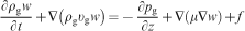
The motion of assistive gases is first calculated using the equations for conservation of mass and momentum, defined as

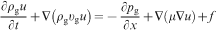
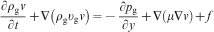
It is assumed that powder particles constituting the stream are spherical in shape. Their motion is calculated by solving the equations for mass and momentum in a Lagrange approach that takes into account drag forces by the surrounding air, and gravity forces. The use of a Lagrange approach offers the advantage that the discrete phase location of particles can be calculated at any point within the domain, regardless of the size of the element of the mesh in which the particle resides. Particle motion is described by the expression16
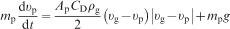
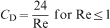
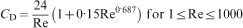
 , CD is the drag coefficient, ρp is the density of the particle and g is the gravity force. The drag coefficient CD is calculated depending on the particle Reynolds number according to


Powder heating
Powder particles emerge from the nozzle having converging trajectories towards a certain zone under the nozzle. As they travel downwards, a number of particles will intersect the path of the laser beam and will be subjected to high energy irradiances that will cause sudden temperature increase. On these conditions, heat transfer in powder particles comprises phenomena of energy absorption, internal conduction and external convection and radiation.
In previous studies of thermal plasma heating of particles, the role of internal conduction within a particle has been studied. In general, it has been shown that the temperature of a single spherical particle rises faster when its thermal conductivity is high, but rises lower with higher specific heat and larger particle diameter.17 Nonetheless, the Biot number, the ratio of convective to conductive heat transfer, can be used as a criterion for determining the relative importance of internal conduction. The Biot number is defined as Bi = hl/kp, where h is the convection coefficient, kp is the particle thermal conductivity and l is the characteristic length, which for a spherical particle is defined as: l = rp/3. It has been shown that if values of Bi are small, temperature gradients within the particle can be treated as negligible. 18 18,19 When Bi = 1, the difference between the centre and surface temperatures of a particle can be 35%,20 but this difference drops to less than 5% if Bi <0·02.17 In this work, where stainless steel powder and argon gas are considered, Bi = 0·004, and thus internal conduction can be neglected.
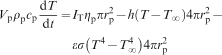
As observed earlier in Fig. 2, particles are also heated by laser energy reflected from the substrate, while at the same time they exchange heat with the surrounding media by convection and radiation. Under these conditions, the energy balance can be described by the following relation

Depending on the absorptivity of the substrate, a portion of the incident energy on it will be reflected back to the surrounding media. It is assumed that this reflection will be of a diffuse nature, according to the Lambert law

Experimental procedure
Three sets of experiments are carried out, and particular emphasis is put on measuring powder stream shape and mass concentration as well as stream temperature under the nozzle.
The general experimental equipment comprises a deposition nozzle coaxially aligned with the centre of the laser beam, a Simatic OP-3 disk powder feeder, a NC table for controlling the motion of the substrate with respect to the deposition head, a supply of argon providing the gas at a constant pressure of 500 000 Pa and a Laserline LDL 160-1500 diode laser coupled to a fibre delivery system. The fibre delivers a circular beam with a waist of 1·6 mm at the focal plane located at 7·5 mm under the nozzle's tip. Stainless steel 316L is used during the experiments. Powder particle size ranges from 53 to 150 μm in diameter.
The first set of experiments was designed to study the powder stream formation. The method used was that of the light scattering from particles illuminated by a thin sheet of light.21 In this method, a high intensity lamp is placed besides the powder stream and a slit mask is positioned between the two. The mask has a narrow groove, which allows a 1 mm thick sheet of light to illuminate a portion of the powder stream. The light scattered by the illuminated particles is captured by a high definition digital camera which is in orthogonal position to the light sheet. Obtained images are processed using commercial imaging software to produce luminance maps. As the luminance is related to the concentration of powder particles present in the stream, the overall concentration of mass within its shape can be calculated. Then, by measuring the diameter of the stream in the axial direction, the overall mass concentration can be used to calculate the axial volumetric mass concentration in the stream. Powder was supplied at a rate of 0·58 g s−1 and the flow of inner and carrier gases were set at 6·67×10−5 and 8·33×10−5 m3 s−1 respectively. The laser was kept off during the experiments, and no substrate was positioned under the nozzle.
The second set of experiments measured the heating of powder particles found under the nozzle, before hitting the substrate. The method was based on direct measurements using a Thermovision Flir A40 thermal camera. The camera was positioned at right angle with the beam axis and aligned with the nozzle tip. The laser power was set at 1000 W, and as previously, powder was supplied at a rate of 0·58 g s−1 and assistive gases were set at 6·67×10−5 and 8·33×10−5 m3 s−1 for the inner and outer flows.
The third set of experiments focused on measuring the amount of powder that is incorporated into the formed clad. The deposition equipment was used according to the settings shown in Table 1.
Parameters for experimental observation of mass deposition
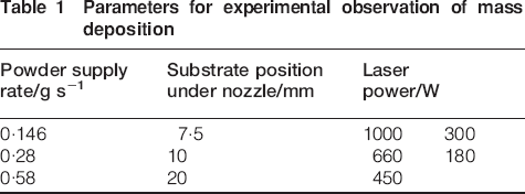
In order to determine the amount of powder added in a clad, single tracks were deposited on stainless steel substrates. The length of the tracks was sufficient to produce an even clad with a smooth surface and no major anomalies such as pronounced undulations or discontinuities. After deposition, samples were cut in the transverse direction approximately half way along the clad. The transverse cross-section represents an average profile along the clad. The clad profiles were measured for width, height and radius of curvature and the cross-section area of the profiles was obtained. This was measured in conjunction with the scanning speed and was used to determine the volume deposited per unit time. This value was then used in conjunction with the density of the material to deduct the rate of mass addition to the track per unit time.
Results and discussion
Powder stream formation
The modelled flow of powder particles is shown in Fig. 3. Two interesting aspects can be observed.
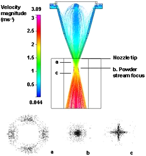
Modelled powder stream (side view) and transverse particle distribution at different in-flight positions: a 4 mm above stream focus point; b at stream focus point: 8 mm; c 3 mm below stream focus point. Carrier gas flow: 8·33×10−5 m−3 s−1; inner gas flow: 6·67×10−5 m−3 s−1; powder flowrate: 0·58 g s−1
The first is that particles enter through the top inlets and experience a sudden collision with the wall of the nozzle, making them decelerate and at the same time to deflect in different directions. They continue to be propelled by the argon gas and gradually gain momentum. During their passage through the nozzle cavity, particles collide several times with the walls, causing them to change directions. These collisions play an important role in determining the final direction that particles have when emerging from the nozzle, and could provide an idea of why the powder stream is found to merge at a position that is different than that predicted by methods based on the geometry of the nozzle. Under the tested parameters, the average stream velocity is 2·3 m s−1, and is predicted to converge at a zone between 7·9 and 10 mm under the nozzle tip.
The second aspect is related to the shape of the stream. At nozzle tip level, the stream is shown to have an annular shape. However, in contrast to what is typically assumed, the distribution of particles within the annulus is not even. As shown in Fig. 3, a higher concentration of particles can be observed at four zones within the annulus, which correspond to the locations of the four nozzle inlets. On moving away from the nozzle, the stream gradually merges into a fully converged spot at the distance mentioned earlier. After converging, the stream diverges again, showing a cross-like shape. Figure 4 shows the concentration of mass in the powder stream directly below the nozzle, on the stream axis. As distance from the nozzle increases, the mass concentration steadily raises until reaching a maximum level after approximately 8·5 mm. After this point, the mass found on the axis of the stream reduces according to its divergence. Good agreement can be observed between the modelled and experimental curves up to the merging zone. After this, the modelled mass concentration falls sharply, while the experimental one observed a more gradual decrement. This could be explained if it is considered that during experimentation, those particles in the centre of the stream that are being directly illuminated by the light sheet could be illuminating particles at the front and rear of the stream by diffuse reflection. This could produce luminance values the concentration of powder in the centre of the stream to be overestimated.
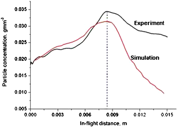
Particle concentration along axial direction (powder flowrate: 0·58 g s−1; carrier gas flow: 8·33×10−5 m−3 s−1; inner gas flow: 6·67×10−5 m−3 s−1)
Influence of substrate position on mass concentration
It has been a common practice in previous works to simulate the powder stream as a free flowing flux of particles, while neglecting the presence of the substrate. It may be that it has been thought that the powder stream can be fully studied as a stand alone element or that the substrate has been considered as not to have an influence on powder stream formation. However, placing a substrate in the simulation shows a significant influence, as can be observed in Fig. 5.
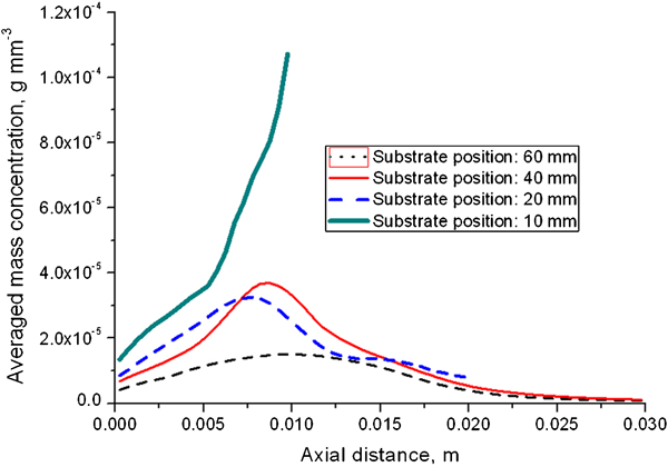
Influence of substrate position on average mass concentration, along axial direction (powder flowrate: 0·42 g s−1; carrier gas flow: 1·33×10−4 m3 s−1; inner gas flow: 1·0×10−4 m3 s−1)
There is a marked increment in powder mass concentration as the distance from the nozzle to the substrate (standoff distance) is reduced. It can be noticed that when the substrate is placed further apart from the nozzle tip, at 60 mm, the smallest mass concentration is found, whereas at a distance of 10 mm, a sharp increase is observed. This is explained by the fact that at such distance, a number of particles hit the substrate outside the boundaries of the melt pool and bounce back into the main stream, thus increasing its overall mass.
Powder stream heating
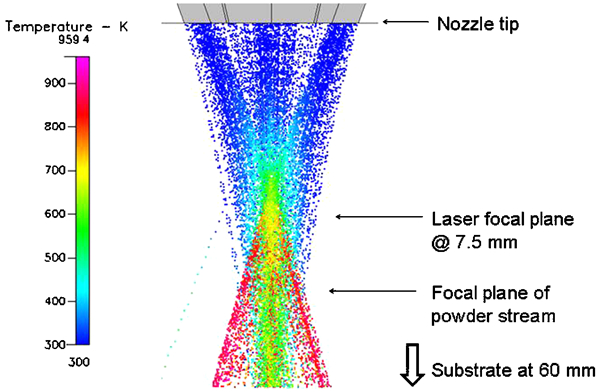
After emerging from the nozzle, powder particles intersect the laser beam. Depending on the geometry of the beam, and their trajectory and velocity, particles can experience significant temperature increases. Figure 6 shows a typical temperature distribution within the powder stream, for the case where the laser power is 1000 W and the standoff distance is 60 mm.
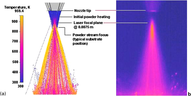
Temperature of free flowing powder stream, after nozzle (power: 1000 W; supplied powder flow rate: 0.58 g s-1; carrier gas flow: 8.33 × 10⁻⁵ m3 s−1; inner gas flow: 6.67 × 10⁻⁵ m3 s−1): a modelled stream; b experimental stream
Initial powder heating occurs 3·5 mm under the nozzle. At this point, the laser beam is still defocused and the temperature rise is moderate. The highest rate of temperature increment occurs when particles cross the focus of the laser beam at 7·5 mm. After this point, the particles irradiated by a defocused beam are still heated, at a reduced magnitude. This fact, in conjunction with the previously explained notion that the powder stream diverges after the merging point, helps to understand why particles on the edges of Fig. 6a observe higher temperatures.
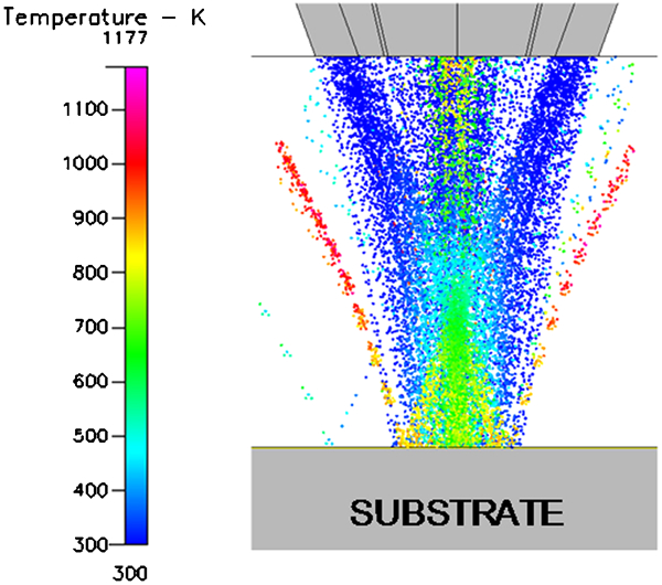
Figure 6b shows a thermal image of the irradiated powder stream, which was obtained according to the procedure described in the section on ‘Experimental procedure’. The obtained readings were found useful to analyse heating trends, albeit not actual temperature in the stream, as the scale in the temperatures was arguably too low. This was deemed to be caused by the fact that the powder stream consists of small particles travelling at high speeds. The powder stream can be regarded as a semitransparent material, whose temperature emission can be affected by the density level of the cloud of particles. As the powder stream, taken as a whole body, has a very low density, the scale in the temperatures recorded was too low to be used for quantitative comparison. Nonetheless, the observed powder stream heating trends showed useful information. It can be observed that the modelled and measured heating trends are closely comparable, particularly in identifying the point at which temperature increase starts and when it reaches a maximum.
This behaviour can also be observed in Fig. 7, where the averaged increase in stream temperature below the nozzle is calculated.
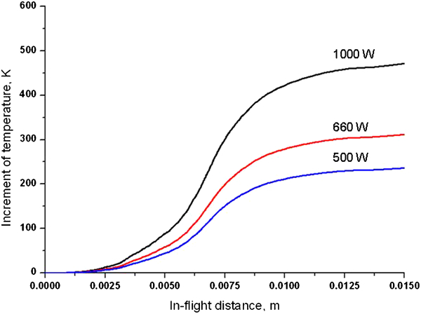
Modelled averaged powder stream heating along axial direction (laser focus: 7·5 mm under nozzle; beam waist: 1·5 mm; supplied powder flowrate: 0·58 g s−1)
It is clear from Fig. 7 that temperature increment initially remains at zero, followed by a zone of moderate increment. The highest gradient in the curves representing heating rate is found around the position of the beam focal plane. After this, temperature continues to increase more gradually. This heating trend is also verified experimentally, as shown in Fig. 8. The effect of standoff distance can also be noticed on powder stream heating. Figure 9 Figures 9 and 10 show two contrasting cases where the standoff distance is 60 and 10 mm. Higher temperatures can be seen in Fig. 10, which can be explained by the effect of particles bouncing back into the bulk of the stream, and being further heated by the laser beam.
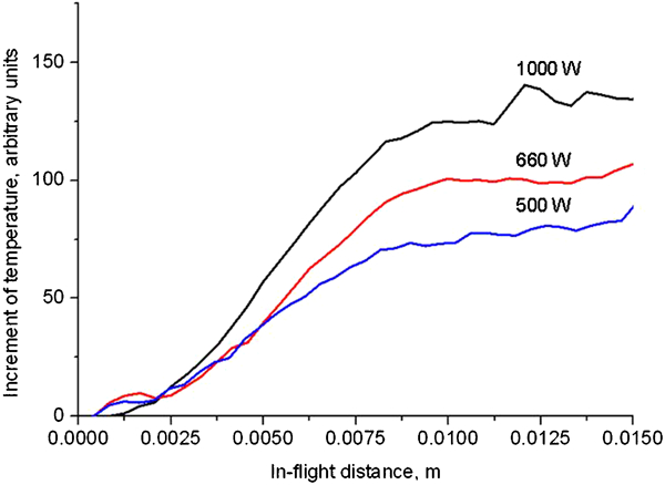
Experimental powder stream heating, measured along central axis (laser focus: 7·5 mm under nozzle; beam waist: 1·5 mm; powder flowrate: 0·58 g s−1)
Modelled stream temperature, half cross-section [power: 1000 W; powder flowrate: 0·58 g s−1; substrate position: 60 mm (substrate is not perceptible on this figure); carrier gas: 8·33×10−5 m3 s−1; inner gas: 6·67 m3 s−1]
Modelled stream temperature, half cross-section [power: 1000 W; powder flowrate: 0·58 g s−1; substrate position: 60 mm (substrate is not perceptible on this figure); carrier gas: 8·33×10−5 m3 s−1; inner gas: 6·67 m3 s−1]
Mass addition
Substrate positioning also affects the efficiency of mass deposition. The size of the melt pool may be changed by the laser intensity, spot size and stream attenuation.
As previously shown, the substrate can alter powder concentration in the stream and cause particles to fall further away from the melt pool, bouncing against the substrate and being lost to the surrounding media. The amount of powder effectively falling into the melt pool per unit time is calculated using the model. The mass of all particles falling within its boundaries, regardless whether they arrive in solid or liquid form, is summed and plotted. Figure 11 shows the modelled and measured mass addition rates at three different standoff distances.
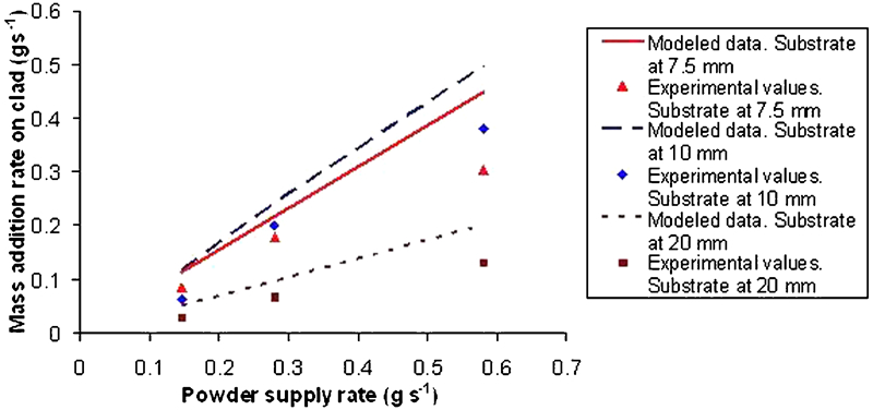
Simulated and modelled rate of mass addition to melt pool, varying substrate positions (laser power: 1000 W; traverse speed: 0·004 m s−1)
A clear linear relation exists between the amount of powder initially supplied into the process and the amount of powder that is actually incorporated into the clad, which could be expected a priori. However, the highest mass addition rate can be observed when the substrate is positioned at 10 mm below the nozzle, which interestingly is not the location of laser focal plane, but rather 2·5 mm under it. At a standoff distance of 7·5 mm, the ratio of mass added to clad against the mass supplied is 78%, whereas when the standoff distance is 10 mm, it is 85%. A modest ratio of 35% is observed when the substrate is located at 20 mm.
The reason for this is that at 0·0075 m, the powder stream is still not fully merged and a portion of particles still fall outside the melt pool, but at 0·01 m the stream has consolidated into a single spot and the maximum amount of particles are falling within the melt pool. Below this distance, and if the standoff distance is increased, the stream diverges, thus increasing the proportion of powder that is lost. A slight overestimation of predicted against measured mass addition rates is observed in Fig. 11, which could be caused by some particles falling near the edges of the melt pool and not being assimilated.
Conclusion
This work presents a computational fluid dynamics based model developed for the study of the laser cladding process. Phenomena of gas and powder particles motion are used for simulating the coaxial powder stream. Particular emphasis is put on analysing particle heating, interactions between the laser beam, powder stream and substrate, and mass deposition into the melt pool. The inclusion of the substrate in the model, in contrast to previous works, allows a simulation closer to real processing conditions.
Key findings derived from this work can be summarised as:
The trajectory of powder particles is mainly determined by wall collisions inside the nozzle cavity and drag forces from the assistive gases. Accurate trajectory predictions cannot be achieved by the sole use of trigonometry and geometrical methods.
The distance from the nozzle tip to the substrate influences the following aspects: mass concentration within the powder stream, overall powder stream heating and mass deposition rate.
Mass concentration in the powder stream is significantly influenced by the standoff distance. As the substrate is positioned closer to the nozzle, the mass concentration tends to increase since more particles bounce from the substrate back into the bulk of the stream.
The amount of mass incorporated into the melt pool is affected mainly by: dimensions of the powder stream, the amount of powder supplied to the process, properties of the powder and the substrate, size of powder particles, laser power, substrate absorptivity, scanning speed and position of the substrate.
The standoff distance at which mass deposition rate can be maximised does not necessarily coincide with the beam focal plane. The ideal standoff distance for each cladding equipment depends mainly on nozzle geometry and flow of assistive gases, which dictate the focusing of the powder stream. The model can be used for optimisation of this output.
Better understanding of the process can be achieved when the important elements presented in this work such as accurate prediction of particle motion, presence of the substrate and interactions between laser beam, powder stream and substrate, are considered at the same time.
Footnotes
Acknowledgements
J. Ibarra-Medina thankfully acknowledges the full support of the Mexican National Council for Science and Technology (CONACYT). This work is also supported by EU FP7 IAAP Agreement 230756 ‘INLADE’. Thanks to project partners Dr M. Megahed and Dr N. A. N'Dri, from ESI GmbH.