
Abstract
In this investigation, a porous oxide coating has been formed on aluminium using direct current anodising technique, sensitised in stannous ion followed by colouring in dilute silver ion at different concentrations and durations to produce pleasing colours ranging from yellow to brown and black. The metallically coloured surface has been analysed using EDAX, atomic force microscopy, X-ray diffraction and ultraviolet–visible–infrared spectrophotometer, and a suitable mechanism has been proposed.
Introduction
Coloured coatings on metal surfaces continue to be a growth technology for decorative, protective and functional applications. New colouring processes are being formulated for anodised aluminium to meet the demands for architectural and solar applications. Anodising is an electrochemical process of producing an oxide film over the surface of aluminium by passing a current at sufficient voltage through a suitable electrolyte using aluminium as the anode and lead or graphite or stainless steel as the cathode. The widely used anodising electrolyte is sulphuric acid.1 – 7
Anodising may be regarded as the artificial thickening of the thin (1–5 nm) native oxide film that is always present on aluminium exposed to the atmosphere. When an electric current is passed through the cell, the aluminium surface is converted into an adherent aluminium oxide coating, which is integral with the aluminium substrate. The film formed consists of a thin barrier layer beside the metal, depending upon the nature of the electrolyte, and a thick porous layer over the barrier layer.8
The porous nature of the anodic coating is advantageously used to incorporate dyes, pigments, corrosion inhibitors or lubricants. Colouring of anodised aluminium is carried out by organic colouring,9 electrolytic colouring7,10,11 and integral colour anodising.12 In the organic colouring process, colouring takes place by the adsorption of the dye in the outer portion of the pores. Very light fast shades of bronze or black were obtained from the electrolyte system containing either Ni or Tin salts by electrodeposition of fine Ni or Tin particles in the pores of conventionally produced oxide films. Electrolytic colouring of anodised aluminium by direct current gives faster and greater yield. Integral colour anodising is carried out using a special type of aluminium alloy or a special organic electrolyte, such as oxalic acid, sulphosalicilic acid+sulphuric acid and sulphothallic acid+sulphuric acid. This process produces bronze to grey shades, depending upon the anodising condition and the alloy employed.
In the present study, colouring was carried out by electroless method, where only the sensitisation and activation treatment involved in the electroless plating of plastic or non-conductor were used. When anodised aluminium was subjected to sensitisation treatment in acidified stannous chloride solution and then with ammoniacal silver nitrate solution, colours ranging from yellow to brown and black shades were produced, depending upon the composition of silver and oxides/chlorides of tin over the oxide layer. The studies include the following:
effect of anodising current density (CD) on coating ratio (CR) and colour formation
effect of stannous ion concentration on colour formation
characterisation of the coating using atomic force microscopy (AFM), energy dispersive X-ray microanalysis (EDAX), X-ray diffraction (XRD) and reflectance measurements using a spectrophotometer.
Experimental
2S aluminium panels of 1×7 cm were subjected to alkaline cleaning in 5%NaOH solution for 5 min followed by desmutting in 25%HNO3 for 2 min, washed, rinsed, dried and weighed W1. The cleaned and weighed aluminium panels were anodised in 10%H2SO4 solution containing 3% sodium sulphate at 15°C. For anodising, 32 V and 30 A Aplab regulated power supply was used along with two multimeters, one at series connection to measure the current and one at parallel connection to measure the voltage across the electrodes. The anodisation block diagram is given in Fig. 1.
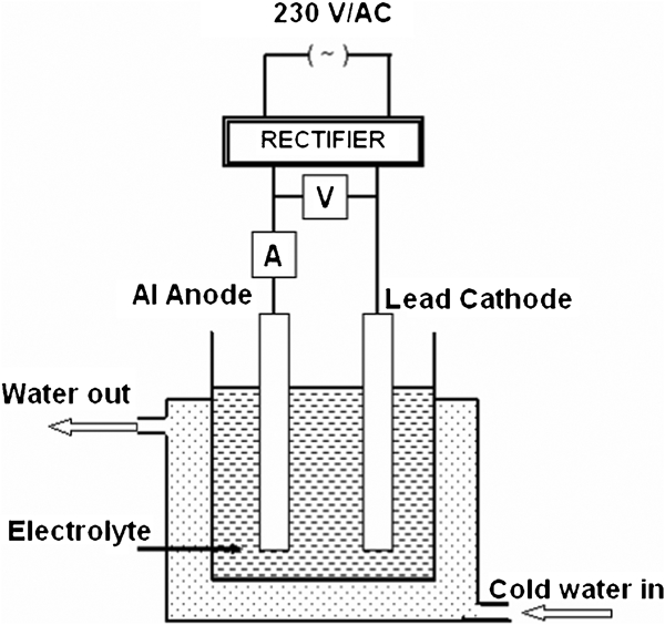
Anodising set-up
A double walled plastic container was used as the anodising cell. Cold water was circulated through the double wall using a fractional horse power pump so as to maintain the electrolyte temperature at the required level. A magnetic stirrer was used to maintain uniform temperature throughout the electrolyte. The weighed W2 anodised aluminium was subjected to stripping in a solution containing chromium trioxide 20 g L−1 and phosphoric acid 35 mL L−1, washed, rinsed, dried and weighed W3. From these weights, the CR was calculated as follows

The anodised aluminium was subjected to colouring by electroless method. The sensitisation treatment solution contains 10–50 g L−1 stannous chloride acidified with hydrochloric acid. It was prepared by dissolving a known amount of tin metal in hot hydrochloric acid and made up to the required volume. The activation solution contains 5 g L−1 ammoniacal silver nitrate and was prepared by dissolving a known quantity of silver nitrate in demineralised water and adding excess ammonia to get a clear solution. The anodised aluminium was first treated with acidified stannous chloride solution for 1–2 min and then with ammoniacal silver nitrate solution for 1–2 min. Colour formation took place during the activation treatment with ammoniacal silver nitrate solution. The anodising CD affects the surface properties of the oxide coating, which determines the intake of tin and silver. The base colours, ranging from yellow to brown and black shades, were produced depending upon the composition of silver and oxides/chlorides of tin over the oxide layer. Characterisation of the coating was carried out using AFM (Digital Instruments CP-II Veeco Company, USA), EDAX (Oxford link ISIS 300), XRD (Philips X'Pert X-ray diffractometer) and reflectance measurements using a spectrophotometer (Hitachi U-3400).
Results and discussion
Effect of CD on coating ratio
The anodising CD was varied from 1 to 5 A dm−2 with an almost constant charge passed by varying the anodisation time. The effect of CD on the coating ratio is presented in Table 1.
Effect of current density on coating ratio
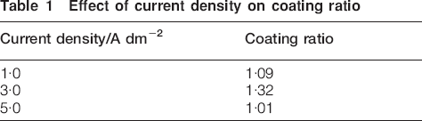
Table 1 shows that there is a fall in coating ratio beyond the CD of 3 A dm−2. The dissolution rate is high compared with the dissolution occurring at lower CDs. A high CD, in turn, increases the local temperature7 at the surface of the anode and facilitates the dissolution of oxide coating, leading to a low coating ratio.
Effect of anodising CD and stannous ion concentration on colour of the film
Anodising was carried out at CDs of 1, 3 and 5 A dm−2. The anodised surface was subjected to sensitisation treatment in stannous ion. In this treatment, there was no colour formation. Colour was produced in the subsequent silver ion treatment only. However, the silver ion concentration has no effect on either variation or intensity of colour formation. Table 2 shows the effect of anodising CD and stannous ion concentration on the colour of the film. It is seen from the table that anodising CDs of 1, 3 and 5 A dm−2 decide the base colour yellow, brown and black formation respectively. Figure 2 shows photographs of yellow, brown and black coloured anodised aluminium anodised at 1, 3 and 5 A dm−2 respectively.
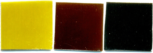
Yellow, brown and black coloured anodised aluminium plates
Effect of CD and stannous ion concentration on colour of film
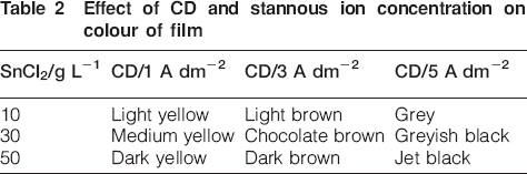
Increasing the stannous ion concentration in the sensitisation solution increases the intensity of the base colour on anodised aluminium. It can be concluded that during sensitisation treatment, the amount of stannous ion intake in the pores of anodised aluminium decides the colour. The amount of stannous ion intake in the pores of anodised aluminium depends upon the anodising CD.
Energy dispersive X-ray microanalysis of coloured film
The coloured coating was subjected to EDAX. Figures 3–5 show the EDAX results of yellow, brown and black coloured coatings respectively.
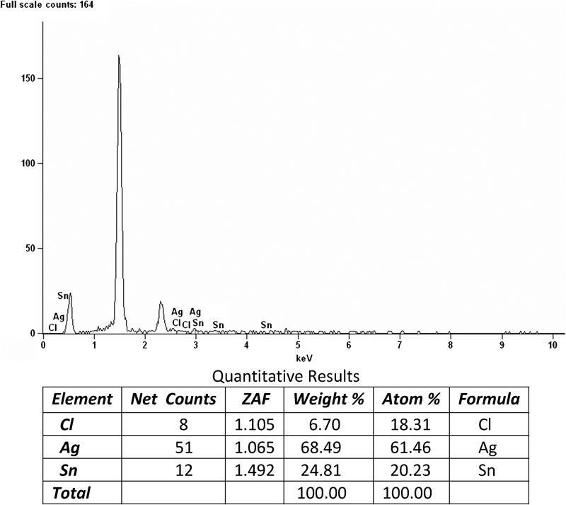
Energy dispersive X-ray microanalysis result of yellow coloured coating
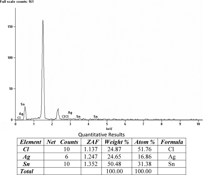
Energy dispersive X-ray microanalysis result of brown coloured coating
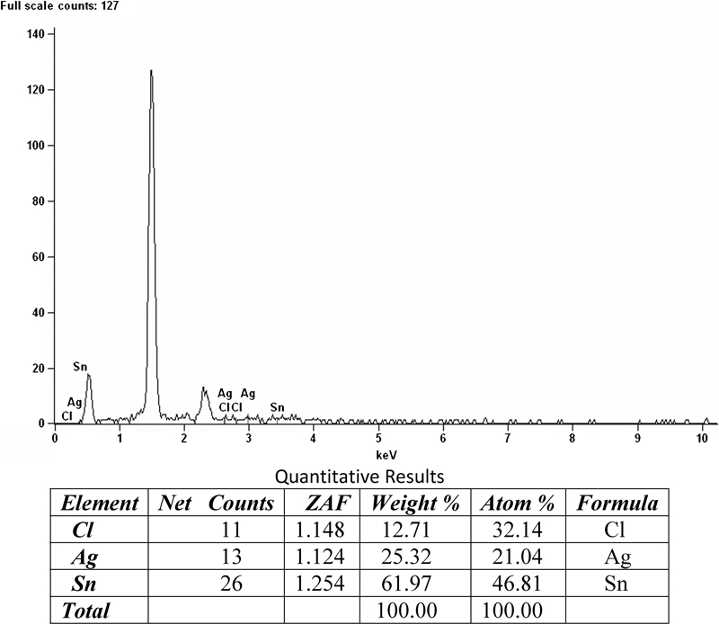
Energy dispersive X-ray microanalysis result of black coloured coating
Figure 3 shows higher silver content than tin, and it also shows some amount of chloride. Figures 4 and 5 show higher tin content than silver, and it also shows chloride presence in the coating.
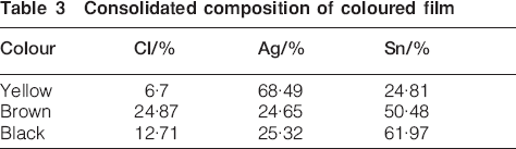
A consolidated composition of the coloured film is given in Table 3. Depending upon the anodising CD, there is a change in topography, which leads to the increase in the specific surface area of the oxide coating. Owing to this change, the intake of stannous ion is varied, which leads to the different compositions of the coloured coating.
Consolidated composition of coloured film
Atomic force microscopic studies
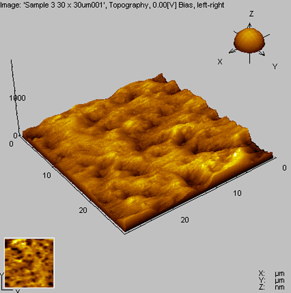
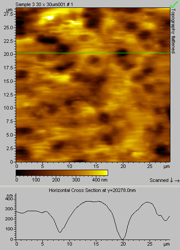
Surface topography of the coloured anodised aluminium surface was found out using AFM. The surface topography and depth profile of the yellow coloured surfaces are presented in Figs. 6 and 7, brown in Figs. 8 and 9 and black in Figs. 10 and 11.
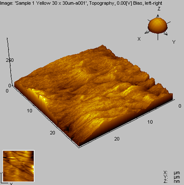
Atomic force microscopy photograph of yellow coloured coating
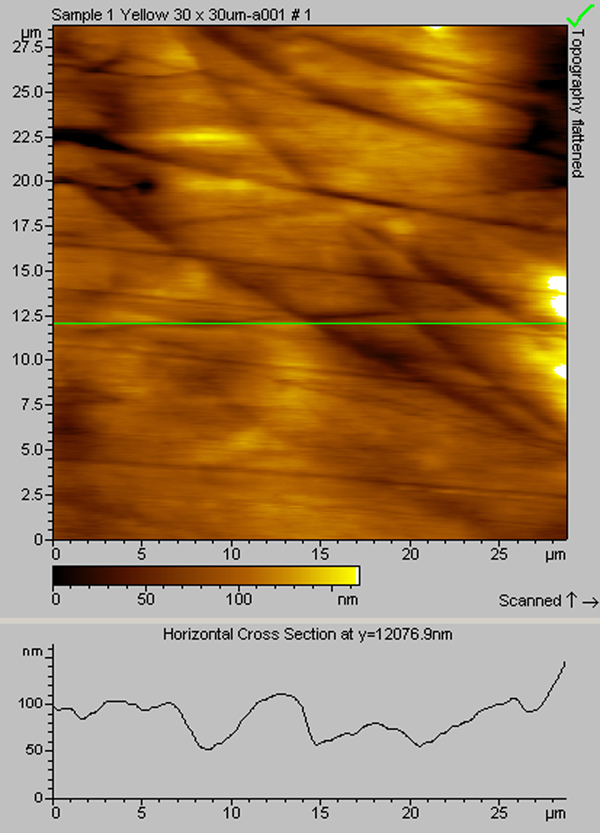
Atomic force microscopy photograph: depth profile of yellow coloured coating
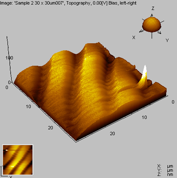
Atomic force microscopy photograph of brown coloured coating
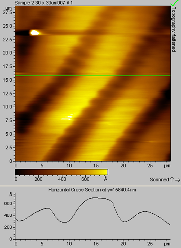
Atomic force microscopy photograph: depth profile of brown coloured coating
Atomic force microscopy photograph of black coloured coating
Atomic force microscopy photograph: depth profile of black coloured coating
It is clear from the figures that the pore depth in the yellow coloured coating is in the order of ∼50 nm, brown is in the order of 100 nm, whereas the black coloured coating is in the order of 200–400 nm ,with higher numbers than the yellow coloured coating. During the colouring process, both tin ions and silver get deposited as nanoparticles at the pores as well as at the plain areas of the anodised surface. This coverage of nanoparticulate matter of different ratios produces different coloured coatings.
X-ray diffraction studies
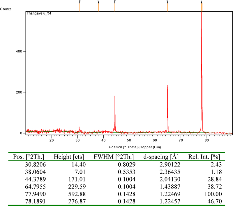
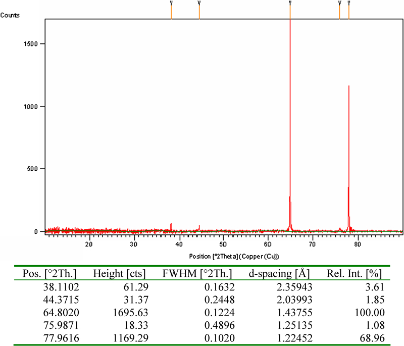
The XRD data for yellow, brown and black coloured coatings are given in Figs. 12–14 respectively.
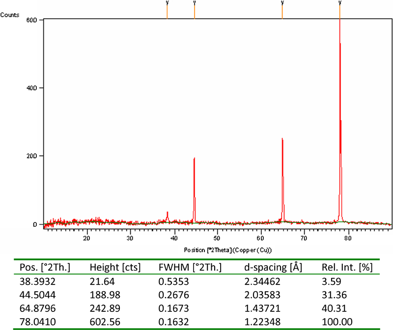
X-ray diffraction data of yellow coloured coating
X-ray diffraction data of brown coloured coating
X-ray diffraction data of black coloured coating
From the XRD data, the average crystalline size was calculated using the following Debey–Scherrer equation
Spectrophotometer studies
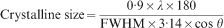
Reflectance measurements were made on the coloured coating using a spectrophotometer in the ultraviolet–visible–infrared region of 200–800 nm. Reflectance versus wavelength for anodised aluminium, yellow, light brown, dark brown, grey and black coloured coatings are presented in Fig. 15.
Reflectance of anodised Al and coloured coatings
Figure 15 shows that an increasing darkness of colour from light brown, dark brown and grey to black decreases the reflectivity. The anodised aluminium shows about 40–50+% reflectivity between 400 and 800 nm. The yellow coloured coating shows ∼40% reflectivity between 550 and 800 nm. The grey coloured coating shows about 5–9% reflectivity. The black coloured coating shows ∼4% reflectivity in the entire spectrum of 250–800 nm. This black coating absorbed ∼96% light in the region of ultraviolet–visible–infrared. This black coating can be used as a solar absorber coating.
The anodised aluminium itself shows a reduction in reflectance value of 50%, which means that the nanoporous nature of the oxide film absorbed ∼50% of the light in the visible region. Further deposition of the nanoparticles of silver and tin oxide/chloride at the pores further increases the absorbance of light to >90%, leading to a black colour. Among the various colours, which are light of a particular wavelength, black colour absorbs light of different wavelengths, especially in the visible region of the spectrum. An explanation for the black colour of black nickel is presented by Rajagopalan et al.13 According to them, there are two phases in the coating: one is the metallic phase, and the other one is the non-metallic/oxide phase. The high reflectivity of the metals is due to the high skin effect, where electromagnetic radiation cannot penetrate far into the metal because of the high electron density. In the present system, the EDAX results and XRD data reveal that both yellow and black coloured coatings contain silver and tin oxide and also contain some amount of chloride. Here, silver is the metallic phase, and tin oxide/chloride as well as aluminium oxide is the non-metallic phase. In the yellow coloured coating, the tin oxide/chloride content is less than the metallic silver particles as the more metallic silver present in the yellow coloured coating is the reason for this 40% reflectance. Whereas in the black coating, the silver particle content is less than the tin oxide with small chloride particles. The AFM results show that the black coloured coating has more number as well as higher depth of pores than the yellow coloured coatings. Hence, it shows an absorbance value of 96% that is the absence of light, leading to this black colour.
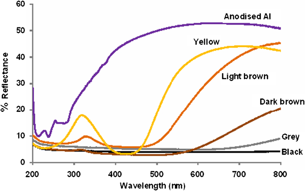
Colouring of anodised aluminium
The porous oxide coating of aluminium above the barrier zone increases its specific surface area, incorporating plain as well as pore areas. A high CD produces a high specific surface area of the oxide coating. After anodisation, when treating with stannous ion, it gets adsorbed into the pores as well as on the other areas of the oxide coating. When combining with silver ion, stannous ion gets oxidised to stannic, reducing the silver ion into silver, as shown in the following equation

Colouring of anodised aluminium by electroless method
Conclusion
Anodising of aluminium in 10% sulphuric acid containing 3% sodium sulphate produces an anodic coating ratio of 1–1·3 at CDs of 1–5 A dm−2 and temperature of 15°C. The anodised aluminium was subjected to colouring by electroless method involving sensitisation and activation treatments. The sensitisation treatment solution contains 10–50 g L−1 stannous chloride acidified with hydrochloric acid. The activation solution contains 5 g L−1 ammoniacal silver nitrate. The anodised aluminium was first treated with acidified stannous chloride solution for 1–2 min and then with ammoniacal silver nitrate solution for 1–2 min. The colour varies depending upon the ratio of silver to tin oxide/chloride. The black coloured coating shows ∼96% absorbance in the visible region. Hence, it could be used for solar absorber applications.
Footnotes
Acknowledgements
The author gratefully acknowledges S. John and P. R. Thangavelu of the Industrial Metal Finishing Division, Central Electrochemical Research Institute, Karaikudi, India, for their help.