
Abstract
Nanostructured anatase TiO2 thin films were deposited at 350, 450 and 550°C on crystalline silicon substrates using ultrasonic spray pyrolysis technique. The thickness of the films decreased with increasing temperature whereas roughness and grain size increased. Adhesive strength of the films was found to decrease with substrate temperature. When steel ball (100 Cr6) was used as the counter body, coefficient of friction (CoF) was found to increase with substrate temperature. In the case of films grown at 350°C, when silicon nitride ball were used as the sliding body, the CoF was found to be high. This anomaly is explained on the basis of three body interaction causing large dissipation of energy.
Introduction
Thin coatings are widely used in mechanical parts and tools because of their high hardness, fracture toughness and wear resistance.1,2 When mechanical parts with thin hard coatings are used in dry sliding conditions, to improve the machining efficiency their coefficient of friction (CoF) needs to be low.3,4 In this context, it is imperative to study the change in CoF with coating materials and process parameters. Nanostructured TiO2 coatings has high strength, fracture toughness, durability, low density, corrosion resistance, biological compatibility and self-cleaning ability which is useful for several applications in chemical and biomedical industry.5 – 9 TiO2 coated silicon is used in MEMS devices due to its unique properties. However, little attention has been paid to study the tribological behaviour of nanocrystalline TiO2 thin films on silicon substrate which acts as a protective layer enhancing the lifetime of the devices. In this regard, the present work is an attempt to investigate the adhesive strength and tribological properties of nanocrystalline TiO2 films deposited on silicon substrate by ultrasonic spray pyrolysis. The effects of substrate temperatures on the structural and mechanical properties have also been evaluated. A wear mechanism is proposed to explain the frictional behaviour of films when silicon nitride and steel ball are used as counter bodies.
Experimental
TiO2 thin films were deposited on silicon substrates by ultrasonic spray pyrolysis deposition technique, which is analogous to atmospheric chemical vapour deposition. The experimental set-up and the parameters required for the synthesis of nanostructured TiO2 thin films are described elsewhere.10 The spray pyrolysis set-up consists of an ultrasonic atomiser, a quartz column and substrate heater. The precursor was prepared by dissolving titanium oxy-acetyl acetonate in methanol (0·05M). The aerosols of fairly uniform size (1–3 μm diameters) generated by the ultrasonic atomiser are transported to the silicon substrates mounted on an overhead heater kept at temperatures of 350, 450 and 550°C, through the quartz column. The aerosols on contacting the substrate evaporate and undergo decomposition reaction on the substrate surface to produce desired nanocrystalline TiO2 films. In each case pyrolysis was carried out for 30 min to make the coatings. The films deposited at substrate temperatures of 350, 450 and 550°C are designated as C-350, C-450 C and C-550 respectively in the text.
The thickness of the films was measured using a surface profilometer (Vecco-Dektek 6 m). The topography and film roughness were studied by an atomic force microscope (AFM, NT-MDT, Russia) in semicontact mode. Scratch tests were performed using a Revetest scratch tester (CSM Instruments, Switzerland). A spheroconical diamond indenter with radius of curvature 200 μm was used as the scratching element. Normal load was applied progressively from 1 to 10 N and scratch length was kept constant at 2 mm. The CoF was measured using a tribometer (CSM Instruments, Switzerland) operated in a linear reciprocating mode. The friction measurements were performed by using 6 mm diameter spherical balls of steel and silicon nitride as counter bodies at a constant load of 1 N and a sliding velocity of 1 cm s−1. Experiments were performed at ambient conditions where the relative humidity was 53%. Morphology of wear tracks was characterised using a scanning electron microscope (SEM, Cam Scan 3200, UK).
Results and discussion
Topographies of the TiO2 thin films deposited on silicon at substrate temperatures of 350, 450 and 550°C were studied using AFM. Figure 1 shows the AFM images of the clusters over a scan area of 5×5 μm. No remarkable change in surface topography with the temperature can be discerned. At a temperature above 350°C, the nucleated clusters grow into substantial sizes and get densely packed. With rise in substrate temperature, these clusters coalesce through diffusion. It is apparent that at high temperature, the film is porous. Columnar growth pattern and anatase phase evolution was observed at all the deposition temperatures. Increase in temperature leads to elongation and pointed out that crystallites grew perpendicular to the substrate surface leading to a columnar growth.11 The thickness of the films was found to decrease with increasing substrate temperature. The thicknesses of the films are 350, 225 and 180 nm for C-350, C-450 and C-550 respectively. Using an AFM, the root mean square (rms) roughness was estimated to study the evolution of the surface patterns. The rms value of roughness lies in the range 2–7 nm. This is significantly less (2 nm) in the case of C-350. But for C-450 and C-550, the measured values of surface roughness are 5 and 7 nm respectively. The increase in roughness is because of the increase in grain size with substrate temperature. The grain size is calculated from XRD pattern using Scherrer formula. The prominent peak (101) at a diffraction angle of 25·3° was considered for their purpose.10 The calculated grain size are 22, 27 and 37 nm for C-350, C-450 and C-550 respectively. The minor peaks (004) and (200) were obtained at diffraction angles of 38·2 and 48° respectively. The morphological characteristics such as grain size, shape and surface area changed with deposition temperature.
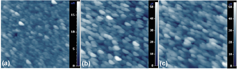
Images (AFM) of TiO2 films. Scan area of AFM images is 5×5 μm:
Progressive load scratch test
Scratch test can be performed under ramped loading to determine the scratch resistance of the coating. This is performed to evaluate adhesive strength between thin film and substrate.12 The smallest load at which the coating is damaged (either by adhesive or by cohesive failure) is called the critical load. This is determined from the acoustic emission signal. In Fig. 2, it is seen that the critical load for failure of the film occurs at normal forces of 5·4 and 3·5 N for films C-350 and C-450 respectively. However, the C-550 film depicts failure at very early stage may be due to residual stress at the interface which can cause de-bonding. This implies that TiO2 is damaged by interfacial spallation and ploughing at critical load associated with the plastic flow of the material. The adhesion, therefore, characterises the rupture strength of the interface or of the transition zone between the coating and the substrate. Critical load for failure is seen to have significant dependence on the substrate temperature. Formation of interdiffusion layer of TiO2–silicon interface acts as an adhesive layer. Strong adhesion is achieved when interdiffusion occurs between coating and substrate. This results in the formation of a solid solution with a progressive transition of composition. The increase in adhesion of TiO2–silicon coatings with decreasing temperature is attributed to the increase in toughness. The critical loads of failure of TiO2 films deposited by RF sputtering at room temperature, 200 and 300°C were found to be 1·51, 1·54 and 1·08 N respectively.12 This shows that the films deposited by ultrasonic spray pyrolysis have better adhesive strength compared to films grown by magnetron sputtering.
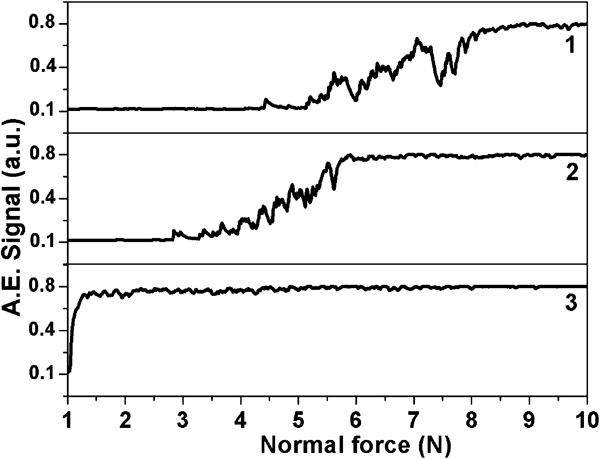
Progressive load scratch test on films synthesised at different substrate temperatures
Tribological test with steel ball
The C-350 film has a low and steady value of CoF (0·26) at the end of passes due to high adhesive strength prevailing between the substrate and film as shown in Fig. 3 (curve 1). Finer grain size and lower surface roughness attribute to the lower adhesion between the sliding surfaces causing low friction. This causes lower dissipation of energy where densification of the film provides low surface energy. Steady value of friction for longer passes is attributed to higher film thickness. The C-350 and C-450 films show low values of steady state CoF 0·23 and 0·37 after 64 and 23 passes respectively. It is clearly shown in the inset of Fig. 3 (curves 1 and 2). The C-550 film shows comparatively higher value of CoF due to large adhesive strength with the surface of film (curve 3). The increase in CoF is also associated with lower film thickness and high rms roughness.
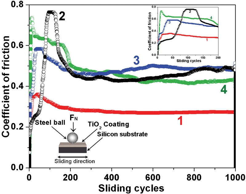
CoF of TiO2 film versus sliding cycles using steel ball
Tribological test with silicon nitride ball
Distinctly different behaviour with regard to the evolution of CoF in TiO2 films/silicon nitride ball is observed. It is noticed from the results that the film thickness and the grain size has considerable effect on CoF. The C-350 and C-450 films have lower steady state value of CoF, 0·23 and 0·25, respectively, while sliding with silicon nitride ball for 45 passes. It is shown in the inset of Fig. 4 (curves 1 and 2). After these passes, the TiO2 film breaks up causing interaction with silicon substrate. The value of CoF for C-550 film and silicon substrate are shown in curves 3 and 4 respectively. Small film thickness and large grain size lower adhesive strength. However, film thickness directly does not affect the interfacial adhesion hence stress confined in the interface has significant effect on adhesion. Diffusion layer and thickness of interfaces are normally higher in high coating thickness which can improve the interfacial adhesion. If the film thickness is lower it can produce larger interfacial stress in the radial direction. The loss of adherence appears at the interface and grows rapidly as the strain increases. This may decrease the fracture toughness of the coatings. The film C-350 shows higher CoF (∼1) after lapse of 42 passes. It can be explained by three body interaction of TiO2 particles involving silicon nitride ball and silicon substrate. This three body interaction causes large dissipation of energy which leads to higher value of CoF. After 647 passes, the CoF decreases to 0·7 when sliding occurs between ball and substrate.
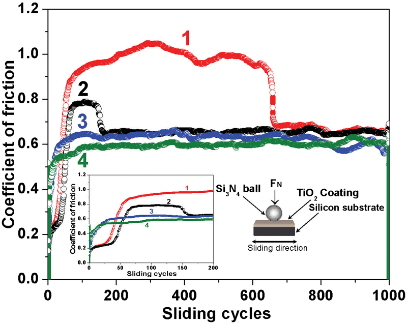
CoF of TiO2 film versus sliding cycles using silicon nitride ball at substrate temperature
The quantity of wear debris generated from film is higher with silicon nitride ball compared to steel ball. It is shown in Fig. 5. As seen in Fig. 5a, silicon nitride ball contact causes extensive grooving accompanied with adhesive failure. The worn out surface of TiO2 films get smoothened out by interaction with silicon particles, generated through dynamic sliding. This particulate mass promotes adhesive interfacial interaction causing deformation of wear surface and ultimately resulting in adhesive wear failure. Once the coating is fractured, coating fragments are ripped out, owing to the effect of shearing action of the counter body. When the coating is partially removed, the rate of this detachment often increases due to excessive contact pressure experienced at the edge of wear scar. In the case of using a steel ball as a counter body, the deformation and abrasion are comparatively less (Fig. 5b). It is understood that the ensuing fracture is induced by plastic deformation and abrasive interaction of these particles with counter body.13 As revealed from the micrographs, sliding with steel ball causes smoother surface than silicon nitride ball. Wear debris and ploughing grooves are also observed on the wear tracks. Interfacial adhesion is the main mechanism at the onset of the sliding as it is the major cause of friction on smooth surface. As the sliding surface is gradually damaged, this mechanism is disrupted and abrasive wear becomes dominant.
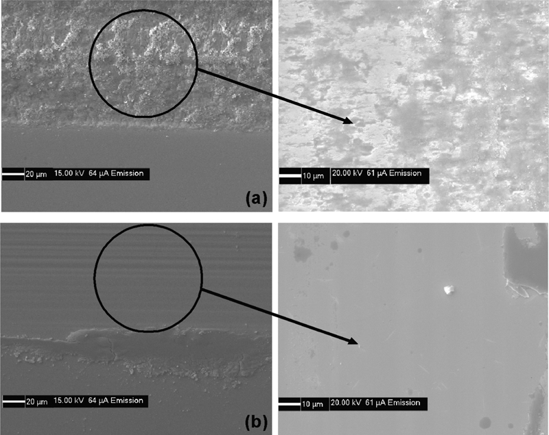
Surface morphology of wear track for film deposited at 450°C with counter face of a silicon nitride ball and b steel ball
It has been described that the adhesive force of TiO2 films surface is lower than that of silicon substrate.14,15 The result implies that the wetting characteristics are also important factors which influence the adhesion. The difference between the friction behaviour of TiO2 thin films and the substrate arises due to differences in surface energy and roughness. Silicon substrate has a lower surface roughness but a higher surface energy than the TiO2 thin films. TiO2 films having high adhesion with substrate and low friction with ball counter bodies. It is observed that at similar applied load the friction force of TiO2 thin films is less than that of silicon substrate.16,17 The rapid increase in friction force after a few sliding cycles is the result of asperity impacts. This leads to high frictional energy dissipation at the sliding interfaces encountered during the use of silicon nitride and steel balls. The CoF is higher with silicon nitride ball due to high interfacial adhesive strength of interface. It has been proposed that silicon nitride ball can react with environmental oxygen and water vapour forming SiO2 and Si(OH)4 which chemically forms mild reactive tribolayer. This layer undergoes easy abrasion leading to larger wear track dimensions.5,18
Conclusion
Tribological properties of TiO2 thin films synthesised using ultrasonic spray pyrolysis deposition technique were studied for the first time to the best of our knowledge. Spray pyrolysis is a cost effective processing technique for making TiO2 coatings. The frictional property was investigated using the steel and silicon nitride balls as static counter bodies. The critical loads for failure of the films grown at 350 and 450°C were found to be 5·4 and 3·5 N respectively, whereas the film grown at high temperature (550°C) showed poor adhesion. The CoF is low (0·23) for the films deposited at 350°C while using the steel ball as a static contact body. The CoF while using the steel ball was low for all the films and higher with the silicon nitride ball. TiO2 coatings having high adhesion and low friction with ball counter bodies may be suitable for application in MEMS and NEMS devices to improve the efficiency of micromechanical sliding.
Footnotes
Acknowledgements
The authors thank Dr G. Mangamma and Mr C. R. Das for AFM and SEM studies respectively. The authors sincerely acknowledge Dr C. S. Sundar, Director MSG for sustained encouragement.