
Abstract
In this study, the chemical vapour deposition (CVD) technique is used to modify the surface of Li2O–ZrO2–BaO–SiO2 glass fibre with Nb2O5, using NbCl5 as the precursor. Glass fibres were coated as follows: without thermal pretreatment but followed by air exposure after the reaction with NbCl5; without thermal treatment followed by water hydrolysis, with thermal treatment at 300°C for 2 h and air exposure; and finally, with thermal treatment and hydrolysis in water. The best result was obtained with the fibre chemically modified with Nb2O5 after heat treatment followed by water hydrolysis. This procedure resulted in fibres coated with a homogeneous layer of Nb2O5 without cracks. The fibres were characterised by scanning electron microscopy and energy dispersive X-ray spectroscopy. The fibres were evaluated in the qualitative determination of a mixture of methanol, ethanol and 1-butanol by solid phase microextraction and gas chromatography, yielding better results than those of the fibre coated with Nb2O5 prepared by metallo-organic decomposition.
Introduction
The surface modification of solids yields materials that can contribute to the development of new analytical methods. Among the techniques used to modify surfaces through the formation of thin films, methods based on metallo-organic decomposition (MOD) and chemical vapour deposition (CVD) stand out.1 The chemical vapour deposition technique is one of the methods most commonly used in the formation of multilayers, fine films, coatings and surface modifications.1 – 3 This technique involves the use of precursors at high vapour pressure and moderate sublimation temperatures, among them chlorides, alkoxides and β-diketones. The CVD technique can be adapted to different precursor excitation methods, one of which consists of a plasma system coupled to a vacuum chamber.2 Another method involves the use of a UHV chamber equipped with a mass spectrometer,3 while one of the simplest methods for using the CVD technique is a high vacuum device coupled to a heating system.4 Both the MOD and CVD techniques can be used to obtain devices for solid phase microextraction (SPME).
In SPME combined with chromatographic techniques, vitreous fibres coated with adsorbents are used. Depending on the physical and chemical characteristics of the coatings, these fibres can provide greater specificity and selectivity to different analytes. New fibres that are potentially applicable in SPME contribute to broaden the range of possible uses of this technique, since most commercial devices are made of glass fibres coated with organic polymers.5 Among the most common adsorbent organic phases are polydimethylsiloxane (PDMS),6 polyethylene glycol (PEG)7 polyacrylate8 and polyaniline,7 and combinations such as PDMS/carboxen,9 PDMS/divinylbenzene10 and PEG/carbon nanotubes.11
Some studies report the applicability of SPME of both alternative supports and coatings, such as gold wire12 and steel fibre13 coated with polyaniline, platinum wire coated with polypyrrole doped with dodecyl sulphate,14 copper wire coated with copper sulphide with a high degree of porosity15 and anodised aluminium16 and zinc wire.17 In this same context, glass fibres coated with inorganic oxides are attractive materials for application in SPME, by combining the thermal stability with the adsorbent capacity of the oxides. As previously reported, coating glass fibres with Nb2O5 by a combined method of sol–gel with dip-coating and MOD has proved useful in the determination of alcohol by SPME–gas chromatography (GC). 18 18,19
In this paper, we describe a study of silica based glass fibres and their surface modification with Nb2O5 by CVD, using niobium chloride as the precursor reagent. We also tested the efficiency of this fibre in determining an alcohol mixture using the SPME technique coupled to GC and compared our findings with those obtained with Nb2O5 coated fibres prepared by MOD.
Experimental
Reagents
The precursor reagents used in the preparation of the glass fibre were Li2CO3 (Vetec); ZrOCl2.8H2O (Vetec 98%); Ba(CH3CO2)2 (Aldrich Chemical) and SiO2 (Aldrich Chemical), all of analytical grade. For the coating we used niobium chloride (V) reagents (Aldrich Chemical). A mixture of alcohols supplied by Aldrich and containing methanol, ethanol and 1-butanol was used to test the efficiency of the fibre.
Preparation of glass fibres
The glass had the following composition: 29Li2O–1ZrO2–5BaO–65SiO2.20 The reagents were weighed on a Sartorius Basic analytical scale with a precision of ±0·01 g. The total mass of the mixture of precursor reagents was 20·00 g. These reagents were mixed by hand in an agate mortar and then transferred to a platinum crucible for subsequent melting. The samples were melted in an EDG-1800 electric furnace in an air atmosphere, applying a heating rate of 10°C min−1 up to a temperature of 1100°C, where they were held for 180 min. Glass fibres were produced by pulling from the mass of melted glass, using a device designed for producing glass fibres.18
Coating of fibres
The glass fibres were coated by CVD, for which a device was set up which combines low pressures with moderate temperatures, as depicted in Fig. 1. Niobium pentachloride was used as the precursor reagent of niobium (V) oxide. In each coating stage, 1 g of NbCl5 was subjected to a sublimation temperature of 140°C, so that the niobium chloride vapours entered into contact with the fibres (three fibres per coating stage) located in an upper compartment in the vacuum line. About 12 tests were carried out, varying the heat and hydrolysis treatments and conditioning the fibres. This paper describes the best coatings. To compare the chromatographic efficiency, fibre coated by the MOD technique was prepared as previously reported.21
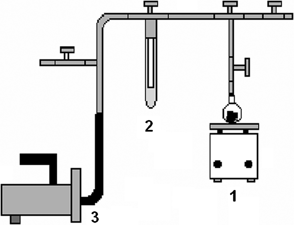
Simplified scheme of system used in CVD technique:
Reuse of hypodermic tube
To use the niobium oxide coated glass fibre in the SPME, we reused the hypodermic tube used in SPME. This involved removing the worn out commercial fibre from the commercial tube by cleaning it with a solution of fluoridric acid (HF 3% v/v) in an ultrasonic bath at 30 s intervals until the hypodermic tube of the commercial SPME device was completely unobstructed, thus allowing the niobium (V) oxide coated glass fibre to be inserted into the clean commercial tube.
Scanning electron microscopy (SEM)
The Nb2O5 layer deposited on the fibre surfaces was analysed by SEM. The samples were attached to a metal support and coated with a fine layer of carbon, using a BAL-TEC CED 030 carbon evaporator. The niobium in the fibres’ coatings was identified and analysed using the ‘Color Map’ surface mapping program. For the chemical analysis, SEM micrographs of the fibres with and without Nb2O5 coating were recorded using a Philips XL 30 scanning electron microscope equipped with an energy dispersive X-ray spectroscope (EDS).
Operating conditions of GC
A gas chromatograph (Shimadzu 14B) was used, equipped with a flame ionisation detector (FID) and split/splitless injector with a 25 m polar column (CBP-20) having an internal diameter of 0·25 mm and film thickness of 0·22 μm.
The heating schedule used in the analysis of the alcohol mixtures was as follows: initial temperature of 40°C for 6 min, followed by an increase in temperature to 150°C at a rate of 10°C min−1, and holding at the final temperature for 2 min. The injector and detector temperatures were 300 and 280°C respectively.
To extract the alcohols, 0·5 cm of the coated fibre was exposed for 20 min to a headspace, at 25°C, of an aqueous solution of methanol, ethanol and 1-buthanol. The individual concentration of alcohols was 50 mg L−1. To release the analytes adsorbed on the fibre, the hypodermic tube with a modified glass fibre was put into the injector, which was kept in the splitless mode for 5 min.
Results and discussion
Optimisation of use of fibre maker
The glass fibres were produced with a fibre maker18 operating by the pulling process. Glass fibres of varying diameters can be obtained by controlling the pulling speed. The device allows one to produce ∼60 cm long fibres in each pulling mode. Daily production may reach up to 15 fibres, totalling 900 cm of fibres/day. In each fibre pulling stage, the crucible containing the melted glass mass is placed in the furnace for 30 min to reach the new melting equilibrium.
The operational parameters of the fibre maker were optimised at 300°C and a pulling speed of 20 rev min−1 to obtain fibres with a diameter of ∼100 μm.
Coating of fibres
Glass fibres with a composition of 29Li2O–1ZrO2–5BaO–65SiO2 were coated with Nb2O5 using NbCl5 as a precursor reagent. The CVD technique was used to produce the respective coatings, as illustrated in Fig. 1.
Earlier studies20 showed that the glass that makes up the fibre contains silanol and siloxane groups distributed internally and externally. Thus, we consider that the reactions between the glass fibre surface and the precursor display characteristics similar to silica gel surface modification reactions. Fibre glass contains Bronsted acid sites (Si–OH) which can promote binding with niobium (V) chloride. However, the use of controlled hydrolysis leads to the formation of the respective oxide.
Characterisation of coated fibres
The layer of Nb2O5 deposited on the fibre's surface was clearly visible by SEM. The ‘Color Map’ (a surface mapping program coupled to the scanning electron microscope) enabled us to identify the niobium in the fibres’ coatings. Qualitative EDS analyses were made of the chemical composition of the coated fibres. An observation of the micrograph in Fig. 2 reveals a glassy matrix with vestiges of crystallisation deriving from the heating state during the fibre pulling process. This treatment is applied to prevent rapid cooling of the melted glass mass and consequent excessive reduction of its viscosity, which would make it difficult to pull the fibre.
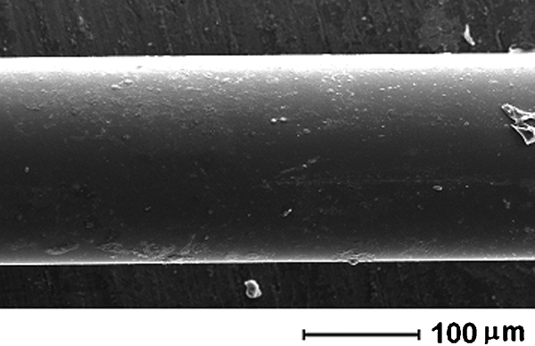
Micrograph of side view of uncoated glass fibre
A comparison of the micrograph in Fig. 2, showing an uncoated glass fibre, and the micrograph in Fig. 3a, corresponding to a glass fibre coated with NbCl5 by the CVD method without any heat treatment, reveals the deposition of a thick layer on the fibre's surface. The image in Fig. 3b indicates that the layer of coating on the glass fibre surface is Nb2O5, with the white dots corresponding to niobium. This image reveals a well defined boundary region corresponding to the respective deposition.
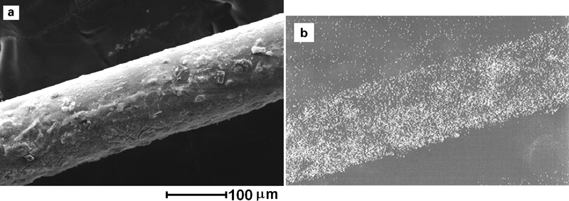
a micrograph and b image analysis of non-heat-treated glass fibre coated with NbCl5 without hydrolysis
The micrograph in Fig. 4a corresponds to a glass fibre coated with NbCl5 and hydrolysed for 24 h in distilled water, also without previous heat treatment. Note the greater irregularity of the Nb2O5 layer on the fibre's surface when compared with the micrograph in Fig. 3a. This is due to hydration of the oxide layer followed by dehydration, leading to the formation of cracks due to swelling/deflation promoted by water.
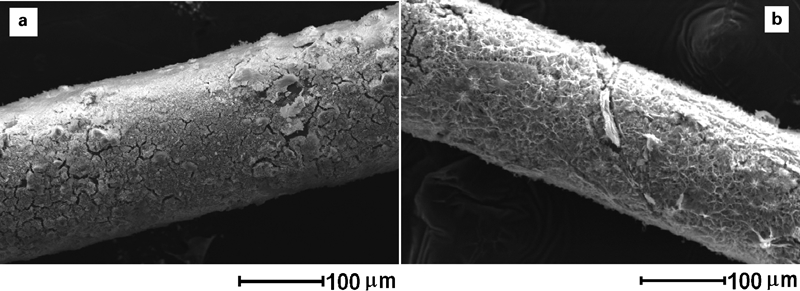
a micrograph of non-heat-treated glass fibre coated with NbCl5 and hydrolysed for 24 h and b glass fibre heat treated at 300°C for 2 h, coated with NbCl5 and hydrolysed for 24 h
The micrograph in Fig. 4b shows a glass fibre previously treated at 300°C for 2 h and subjected to a reaction with NbCl5 followed by hydrolysis for 24 h. A homogeneous layer of coating is formed along the longitudinal section of the glass fibre, which was also identified as niobium pentoxide by niobium Kα line mapping.
The previous heat treatment releases the Bronsted acid sites on the fibre surface. The release of reactive sites allows for a greater degree of coating with the oxide precursor, which, after hydrolysis, prevents the formation of cracks.
Chemical analysis
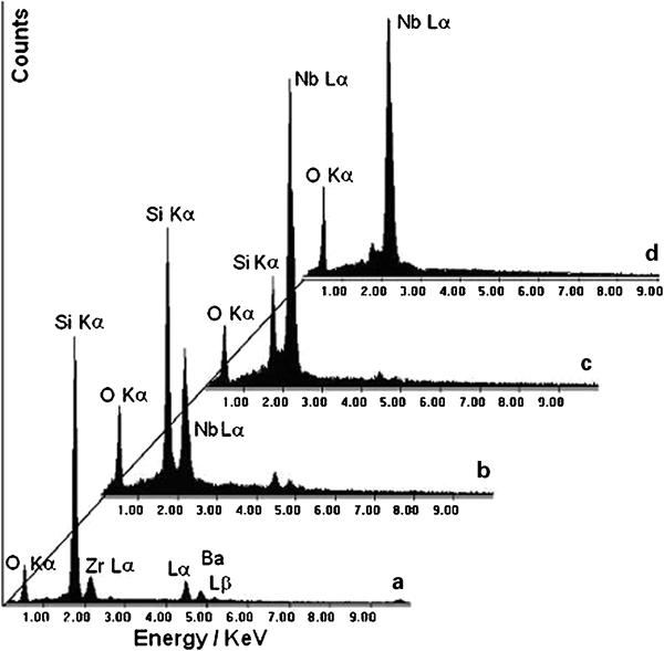
The compositions of the glass fibres without coating and coated with Nb2O5 were analysed qualitatively by EDS, confirming the results obtained by SEM. The spectrum of the glass fibre shown in Fig. 2 is presented in Fig. 5a and reveals only the presence of peaks representing the SiO2, ZrO2 and BaO oxides that make up the fibre. However, because Li is a very light metal, it was not determined or detected by EDS.
EDS spectra of glass fibres:
The spectrum in Fig. 5b, which depicts the chemical analysis of a glass fibre coated with Nb2O5 without heat treatment and without controlled hydrolysis (corresponding to the Nb2O5 coated glass fibre in Fig. 3a), shows an increase in the peak at 2·2 keV when compared with Fig. 5a. This increase may be attributed to the Lα emission lines of both zirconium and niobium. This increase resulted from the large amount of niobium on the glass fibre surface.
Figure 5c shows the spectrum of the glass fibre coated with niobium oxide, which was not heat treated but subjected to 24 h of controlled hydrolysis in distilled water. A considerable increase in peak intensity at 2·2 keV was also found. Note the sharp drop in the silicon peak resulting from the difficulty of the electron beam to pass through the thick layer of Nb2O5 coating on the surface of the glass fibre to reach its glassy core. This was also observed in the fibre heat treated and coated with Nb2O5, and subjected to 24 h of controlled hydrolysis in distilled water, as shown in Fig. 5d. As can be seen, the silicon peak of both coatings is less marked while the niobium peak is more evident. This finding confirms what had already been observed by SEM and ‘Color Map’ image analysis, i.e. that this coating contained a larger amount of deposited Nb2O5 modifying the glass fibre surfaces. Furthermore, hydrolysis was efficient both in air and in water, since the chlorine peaks in the corresponding spectra are absent.
Efficiency of coated fibres
The efficiency of the niobium oxide coated fibres was evaluated by SPME–GC. All the fibres coated with Nb2O5 were evaluated. However, in this paper we present only the results of the heat treated fibre (300°C/2 h) after hydrolysis, for it was the coated glass fibre that displayed the best chromatographic result. This was confirmed by the analysis of the mixture of alcohols containing methanol, ethanol and 1-butanol.
Figure 6 shows the chromatograms of the same mixture of alcohols obtained for Nb2O5 coated fibres produced by CVD and MOD. Both chromatograms show the presence of three separate and well defined peaks, each one corresponding to its respective alcohol. The first peak, with a retention time of ∼2·3 min, corresponds to the release of methanol; the second, with a retention time of 2·7 min, indicates the outgoing ethanol; and the third peak, with a retention time of 7·9 min, corresponds to the 1-butanol. The fibre coated by CVD displays more intense peaks than the fibre coated by MOD, presumably due to a larger number of adsorption sites. Moreover, the chromatographic analysis using the fibre coated by CVD revealed methanol and ethanol peaks with the same intensity, while the fibre coated by MOD showed a less intense ethanol peak. Therefore, the Nb2O5 coated fibre produced by CVD proved to be more efficient in adsorbing the mixture of alcohols by SPME, providing qualitatively excellent results.
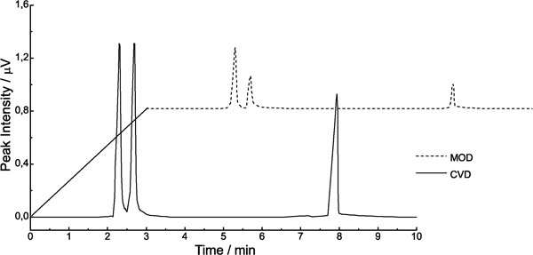
Chromatogram of mixture of alcohols containing methanol, ethanol and 1-butanol (individual concentration of 50 mg L−1) obtained after extraction by SPME technique, using Nb2O5 coated glass fibres obtained by MOD and CVD
Surprisingly good results were also observed for the Nb2O5 coated glass fibre, which displayed high durability and was used in about 180 analyses, as well as high thermal resistance when used under conditions of extreme exposure in the chromatograph, and high capacity of adsorption, separation and selectivity for the SPME–GC technique.
Conclusion
The CVD technique with a heating system coupled to a vacuum line proved very efficient for coating fibres with niobium (V) oxide using NbCl5 as the precursor, producing fibres with a thick and homogeneous coating along their entire longitudinal section after hydrolysis. The best coating was obtained with glass fibres that were preheated for 2 h at 300°C before the reaction with NbCl5 followed by hydrolysis in water. The coated fibres proved to be promising for the determination of a mixture of methanol, ethanol and 1-butanol by SPME and GC.
Footnotes
Acknowledgements
The authors acknowledge the financial support of Conselho Nacional de Desenvolvimento Científico e Tecnológico – CNPq (Brazil) and Programa de Ciência e Tecnologia – PTI C&T.