
Abstract
High velocity arc spraying and cold gas dynamic spraying were applied to prepare the aluminium coating, and electrochemical impedance spectroscopy measurement in combination with scanning electron microscopy analysis of corrosion surface and X-ray diffraction results of corrosion product were used to compare the corrosion behaviour of these two coatings. It was found that there was sparse and porous corrosion product covering on the surface of the arc sprayed aluminium coating through which the Cl− can penetrate into the inner coating interface. In contrast, the surface of the cold sprayed aluminium coating after immersion was less porous and tended to seal the pores in the coating. This kind of structure can obstruct the penetration of corrosion medium into the inner coating surface and reduce the corrosion rate to a certain extent. In addition, the diffusion impedance O was introduced in the electrochemical impedance spectroscopy modelling for the purpose of getting good fitting results.
Introduction
Marine structures, such as bridges, pipelines, ships and offshore structures, have been severely degraded in marine environment. It has been reported that paint and metallic coatings can durably protect the structures from corrosion. Aluminium coatings deposited on the steel structure have good corrosion resistance under the marine environment.
Different techniques have been used to deposit aluminium coatings on steels,1 – 4 such as electroplating, chemical vapour deposition, hot dipping, thermal spraying, etc. Among them, arc spray (AS) is a thermal spraying method used frequently. However, the technique will heat the material to melt, which involves oxidation, burning loss of element and phase transition in the process. As a result, the coatings will degrade with these phenomena.
Cold spray (CS), as a novel surface treatment technique, was invented in the 1980s at the Institute of Theoretical and Applied Mechanics, Russian Academy of Science in Novosibirsk. In the CS process, spray materials adhere to the substrate only due to their high kinetic energy upon impact. Depending on the spray particle diameter and density, the carrier gas properties as well as the nozzle geometry, the particles will be accelerated to supersonic velocities ranging from 500 to 1500 m s−1.5 Because of the relatively lower deposition temperature, oxidation and other undesired reactions can be avoided in comparison to conventional thermal spraying processes. Furthermore, the CS coatings are characteristic for the lower porosity than thermal spray coatings.
Aluminium coatings have been successfully deposited on different substrates by CS. Previous studies6 – 11 have described deposition mechanism, preparation technology and surface characteristic of CS aluminium coating. The corrosion performance of CS aluminium coating has also been studied.12, 13 However, most of these investigations are mainly focused on the general corrosion resistance. The detailed corrosion behaviour of CS aluminium coating compared with AS aluminium coating is rarely reported. Choi et al.7 studied the integrated characterisation of CS aluminium coatings. They found that the coating displayed a network of interlocking splats, boundaries and pores. Moreover, the top layer of the coating was well bonded and showed approximate equiaxed crystallite structure. Tao et al.12 studied the corrosion performance of CS aluminium coating. In their study, electrochemical testing showed that the CS aluminium coating had better pitting corrosion resistance than bulk pure aluminium in neutral 3·5 wt-%NaCl solution. In addition, their electrochemical impedance spectroscopy (EIS) tests revealed that a mass transfer step was involved in the corrosion during immersion.
This work aims to investigate the difference in corrosion behaviour between CS and AS aluminium coating. Here, the coated substrates were examined before and after immersion in sea water. In particular, the EIS behaviour and the morphology of the coatings after different immersion times have been studied.
Experimental
Materials and coating preparation
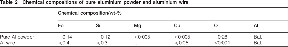
Sheets of Q235 steel (100×50×5 mm) were used as substrates. The chemical composition of the steel is shown in Table 1. Before the coating preparation, the substrates were sand blasted using alumina grits in order to remove the remaining oxides and oil, which will decrease the coating adhesion. Pure aluminium powder produced by gas atomisation and sieved through 300–500 mesh standard screens was used as CS material. The CS novel had a converging–diverging geometry; the diverging portion of the novel was conical and 100 mm in length, with throat and exit diameters of 2 and 5 mm respectively. Aluminium powder was fed into the novel at 1·6 g s−1. The spraying standoff distance was maintained at 25 mm. The carrier gas (N2) was preheated up to 250°C at a pressure of 2·0 MPa. An autocontrolled spray gun moved at a speed of 10 mm s−1 in front of the substrate. The whole CS process was controlled by a precompiled computer program to ensure good reproducibility of the coating specimens. As a comparison, the aluminium coating deposited by AS was also used in this study. The aluminium wire (2·0 mm, ∼99·7% purity) was used as feedstock material. The chemical compositions of both pure aluminium powder and aluminium wire are listed in Table 2. Compressed air was used as carrier gas. The spraying parameters are summarised in Table 3.
Chemical composition of Q235 steel

Chemical compositions of pure aluminium powder and aluminium wire
Deposition conditions of AS Al coating

Test methods
The samples were immersed in natural sea water (Qingdao, China) at 25°C for different periods of time. Electrochemical measurements were performed using a Princeton Applied Research 2273 electrochemical workstation. A conventional three-electrode cell was used during the electrochemical tests. The working electrode was the investigated sample, exposing 1·0 cm2 of the surface to sea water. The counter electrode was a platinum plate, and all the potentials were measured with respect to the saturated calomel electrode. If there is no special indication, all the potential values in this report are quoted with a saturated calomel electrode. The EIS measurements were performed in potentiostatic mode at open circuit potential. When the corrosion potential remained stable, a sinusoidal ac perturbation of 5 mV (root mean square) amplitude coupled with the corrosion potential was then applied to the electrode at frequencies ranging from 100 kHz to 0·01 Hz. The software ZSimpWin was used in this study for EIS data analysis, which allowed non-ideal electrochemical behaviour to be modelled, using the constant phase angle element to replace pure capacitance and provided other complex circuit elements suitable for the investigation of diffusion and mass migration.
Sample morphologies were investigated by scanning electron microscopy (SEM) using a JSM-6700F instrument. The X-ray diffraction (XRD) patterns were obtained by a D/MAX-2500/PC diffractometer (X-ray was Cu Kα radiation with λ = 0·154056 nm).
Results and discussion
EIS spectrum and analysis
The EIS data, which were collected from aluminium coated steel after 24, 72, 240 and 480 h exposure to natural sea water, are presented in Fig. 1. For the CS aluminium coating, two time constants are observable in Fig. 1a during the earlier stage. The one appearing at high frequency characterises the break of the original oxide film, while the one at low frequency represents the corroding of fresh aluminium coating by corrosion medium. As shown by the broken lines in the plots of Fig. 1a, the positions of peaks at high frequency remain unchanging with the immersion time. However, the positions of peaks at low frequency shift towards high frequency as the time increases, indicating that the dielectric property of the CS aluminium coating may be influenced due to the immersion in sea water. For the AS aluminium coating, there are also two time constants observed in the plots. However, the positions of the two peaks shown in Fig. 1b change along with time, suggesting that the dielectric property of the AS aluminium coating is also affected due to the exposure. In addition, the peak highlight at high frequency (Fig. 1a and b) decreases with exposure time, indicating that the coating becomes less capacitive. Moreover, the peak highlight at low frequency rises and falls irregularly. We infer that the formation and dissolution of corrosion product film are simultaneous events.
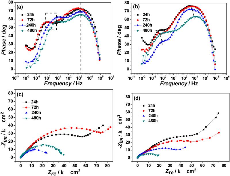
Bode phase and Nyquist plots of aluminium coating with time immersed in sea water: a, c plots of CS aluminium coating; b, d plots of AS aluminium coating
Figure 1c demonstrates the typical Nyquist plots of the CS aluminium coatings. During the earlier stage, the curves show a capacitive loop in the high frequency range and an approximately straight line in the low frequency range, which indicates that a mass transfer step is involved in the corrosion process. In this report, the mass transfer step may involve the diffusion of reactants and products, such as oxygen and Cl−. During the later stage, the pure capacitive behaviour as a common feature appears in all the EIS plots. The diameter of the loops decreases sharply compared with the earlier stage. In Fig. 1d, the Nyquist plots of the AS aluminium coating reveal roughly the same trend. However, the pure capacitive loop comes later than that of the CS aluminium coating.
In the Nyquist diagrams shown in Fig. 1c, the diameter of the capacitive loop at low frequency shifted to a higher value from 240 h of immersion to 480 h of immersion, which indicated that the polarisation resistance Rp of the CS Al coating increased in this period of immersion. After immersion for 480 h, the capacitive loop at low frequency of the CS Al coating was much larger than that of the AS Al coating, which showed that the Rp of the CS Al coating was higher than that of the AS Al coating. However, after 240 h of immersion, it should be pointed out that the Rp of the AS Al coating was higher than the Rp of the CS Al coating. According to the analysis, it was relevant to the corrosion product on the coating surface. At this stage, there was much corrosion product on the AS Al coating surface. Furthermore, the localised corrosion was not severe. Therefore, the AS Al coating exhibited a higher Rp than the CS Al coating after immersion for 240 h. However, taking account of the whole immersion process, the corrosion resistance of the CS Al coating is higher than that of the AS Al coating.
Taking Bode and Nyquist plots into consideration, we separate the corrosion of aluminium coating into two steps. The first step is the rapid attack occurring on the external surface of the coating and the inner surface of the pore. Consequently, the corrosion products accumulate in the defects, which will prevent the solution from further penetration. The second step is the development of localised corrosion, and thus, the pores will deepen and widen, and the mass transfer will be free from obstruction. Eventually, the impact of diffusion on corrosion has been gradually weakened.
EIS equivalent circuit (EC) and modelling
Based on the above mentioned analysis of the EIS spectrum, we initially established the ECs for different immersion times of aluminium coating. The EC for the earlier stage is Rs {Cc[Rc W(Cct Rct)]}, while the Rs {Cc[Rc(Cct Rct)]} is for the latter stage, as shown in Fig. 2. In the circuits, the symbols of Rs, Rc, Rct, Cc, Cct and W represent solution resistance, coating resistance, resistance of charge transfer, coating capacitance, electric double layer capacitor of the electrochemical reaction and Warburg impedance respectively. However, modelling using the two ECs did not give a satisfactory fit to the experimental spectra. This is attributed to the use of ideal elements in the ECs. By replacing capacitors C with constant phase elements Q, the fitting precision using Rs {Qc[Rc(Qct Rct)]} produces a significant improvement. Similarly, for the EC of the latter stage, the substitution of Qs for capacitors significantly improved the fitting results. However, further improvement of fit has been achieved by introducing a co-tangent hyperbolic diffusion impedance O to replace the Warburg impedance W.
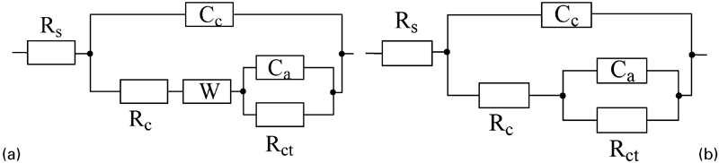
Equivalent circuit of Al coating in sea water for different times: a R{C[RW(CR)]}; b R{C[R(CR)]}
As investigated by Liu,14 the diffusion of reactant agents (e.g. Cl−) in the electrochemical corrosion of coated steel is microscopically confined within pores or grain boundaries. Therefore, the microstructure of the aluminium coating can significantly influence the diffusion behaviour. They found that the Warburg impedance is most suitable for columnar crystallite, while the cotangent hyperbolic diffusion impedance O is best for the equiaxed crystallite structure. Apparently, the top layer of both CS and AS aluminium coatings is of approximate equiaxed crystallite structure.7 This is why we use O to replace W in the ECs for the aluminium coated steel.
Corrosion behaviour analysis on basis of EIS fitting
Based upon the EC illuminated in Fig. 2, the EIS data are analysed using a complex non-linear least square fitting method. The variations in the fitted values of log Rc and log Rct are presented in Fig. 3, which shows that the final values of Rc and Rct are similar for CS and AS aluminium coatings. The difference is that for the CS aluminium coating, Rc varies less than that for the AS aluminium coating, and Rct varies in a greater extension than that for the AS aluminium coating. It is related to the localised corrosion and generation of corrosion products.
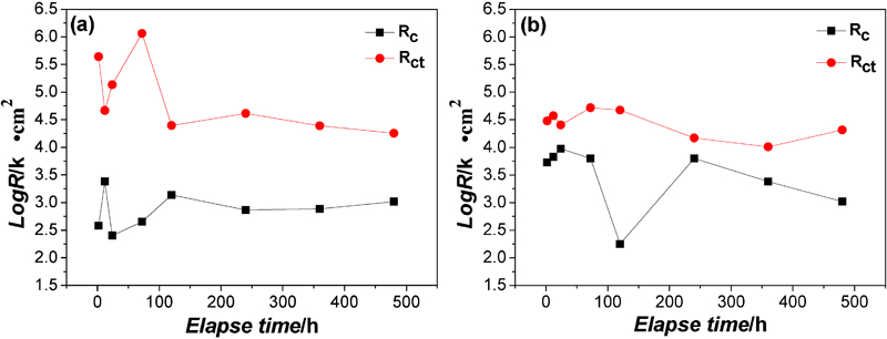
Variation in Rc and Rct of Al coatings with time in sea water: a CS Al coating; b AS Al coating
For the CS aluminium coating (Fig. 3a), because the oxide film on the surface occurs naturally, Rc immersion for 2 h is 0·38 kΩ cm2, and it turns to a lower value of 0·25 kΩ cm2 after 24 h due to the attack of Cl−. At the primary stage of immersion (no longer for 120 h), as many pores are filled with solution and much corrosion product accumulates in the defects, the localised corrosion is becoming more active. After immersion for a longer time, Rct and Rc reach relatively stable states (Rc, ∼1·04 kΩ cm2 and Rct, ∼17·9 kΩ cm2), which indicates that the localised corrosion proceeds slowly due to the active dissolution of the defects and piling up of the corrosion product. The resistance maintains a constant value in the latter stage of immersion, which illustrates that the CS Al coating has a very high corrosion resistance.
For the AS Al coating (Fig. 3b), the Rc of the oxide film is larger than the CS Al coating at the beginning of the immersion because of the aluminium oxidation in the preparation process. After immersion for 2 h, Rc is 5·32 kΩ cm2, which is effective in protecting the passive film from Cl− attack. As a consequence, the oxide film or corrosion product will build up a barrier to hinder corrosion rather than dissolution. Furthermore, it exhibits a higher value of Rc after 24 h, 9·47 kΩ cm2. It has been illustrated that there are many pores existing in the coating, and the solution can penetrate through them into the inner surface. The localised corrosion dominates the corrosion process, which results in the break of the original oxide film so that the value of Rc diminishes greatly and shows a value of 1·05 kΩ cm2 after 480 h. It can be confirmed that the AS aluminium coating shows a faster degradation, and the CS aluminium coating can provide a stable corrosion protection for the substrate.
Morphology change by corrosion
A surface morphology comparison between the CS and AS Al coatings after 720 h immersion in sea water is shown in Fig. 4. It can be found that only a little corrosion product can be observed on the surface of the CS Al coating. As you can see, there are regions without corrosion product in Fig. 4a, and they are still aluminium coating rather than steel substrate. Accordingly, the corrosion product is not a guarantee against corrosion by chloride ions. However, the corrosion product can block the pores of the coating and obstruct the penetration of corrosion medium into the inner coating surface and reduce the localised corrosion rate to a certain extent. Dissimilarly, a much sparse corrosion product appears on the surface of the AS Al coating, and numerous local pores are enlarged. From this contrast, it is clear that the CS Al coating has a higher corrosion resistance than the AS Al coating.
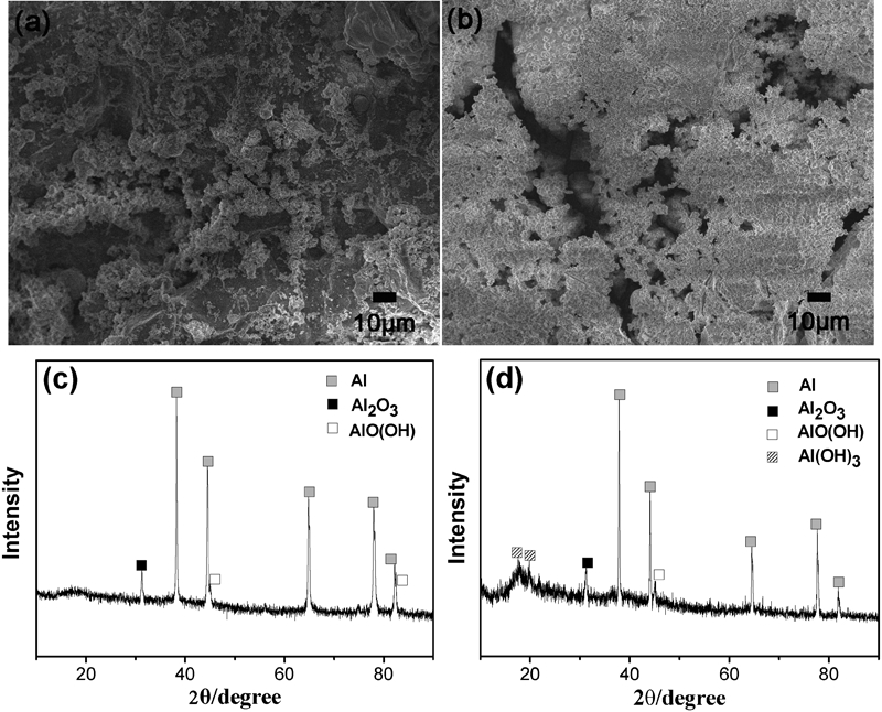
Scanning electron microscopy surface morphology and XRD analysis of aluminium coatings after 30 day immersion in sea water: a, c SEM image and diffractogram for CS aluminium coating; b, d SEM image and diffractogram for AS aluminium coating
To further investigate the corrosion product, the corrosion specimens were characterised by XRD. Figure 4c and d shows the patterns of CS and AS aluminium coatings post-corroded respectively. The different substance phases are identified. From the pattern illustrated in Fig. 4c, Al, Al2O3 and AlO(OH) were the compounds of the CS Al coating surface identified. During the CS deposition process, the atmosphere contains only N2, and we assume Al2O3 is formed in the air after preparation. However, AlO(OH) comes into being naturally in sea water. The pattern of Al coating depicted in Fig. 4d reveals a great difference in component in relation to the CS Al coating. Al(OH)3 can be observed in the surface coating. It is a porous layer, through which the corrosion medium will penetrate into and corrode the inner metal surface of the coating, as previously reported.15 As a result, localised corrosion occurs in the pores of the coating. It is characterised by the production of acid solution in the occluded corrosion cell owing to the self-catalysis acidification effect. This is why the AS aluminium coating shows a faster degradation than the CS aluminium coating.
Conclusion
The corrosion behaviour of CS and AS aluminium coatings has been studied through fitting the EIS spectra at different immersion times in natural sea water. The obtained parameters can provide a wealth of information on corrosion reaction, mass transfer and dielectric property of aluminium coating. Furthermore, the morphology and corrosion product has been respectively detected by SEM and XRD analysis.
The EIS spectra from CS and AS aluminium coating systems showed two time constants, while the positions and highlights of peaks between the two systems were different. The changes in positions and highlights indicated that the dielectric property of both CS and AS aluminium coatings was influenced due to the immersion in sea water. The constant at low frequency represented the electrochemical response of the localised corrosion, which was different from the one at high frequency.
The CS aluminium coating has better corrosion resistance than the AS aluminium coating, which was attributed to the denser microstructure of the coating and corrosion product. It was found that there was sparse and porous corrosion product covering on the surface of the AS aluminium coating through which the Cl− can penetrate into the substrate/coating interface. In contrast, the corrosion product of the CS aluminium coating was dense and can greatly protect the steel substrate from the corrosion medium.
Herein, we introduced the co-tangent hyperbolic diffusion impedance O in the ECs rather than the Warburg impedance W to describe the diffusion process, which can bring more accurate fitting results.