
Abstract
Ultrasonic was introduced during pulse plating process to prepare NiFeP alloy films. Effects of different duty ratios and ultrasonic powers on composition, microstructure and magnetic properties of films were investigated. With the rise in duty ratios, the amount of nickel increased gradually. Higher ultrasonic power could result in larger contents of iron in NiFeP alloy films. That was because nickel reduction was potential controlled while iron reduction was diffusion controlled during the pulse plating process. Almost all the deposited films were crystalline and formed peaks of FeNi3 (111), FeNi3 (200) and FeNi3 (220). With the increase in duty ratios, the intensity of all three peaks started to decline, which led to worse crystalline and bigger grain sizes. Dissimilar surface morphology could be detected by the condition of different duty ratios and ultrasonic powers. NiFeP films with smaller grain size and smooth surface could be obtained when a higher power of ultrasonic was introduced during the pulse plating process. However, the films with rough and agglomerate nodular structures would be observed with higher duty ratios. Vibration sample magnetometer results showed that the coercivity of NiFeP films ranged from 30 to 150 Oe.
Introduction
With rapid development of information society, there is a great need for small size and optimum performance magnetic thin films. Much more attentions have been paid to NiFe magnetic thin films these days. Because NiFe alloy films are ferromagnetic materials with lower linear expansion over temperature ranged between 20 and 200°C, they are usually utilised in magnetic headers.1 In addition, NiFe alloy films possess lower coercivity and high performance against corrosion, which play a significant role in many soft ferromagnetic applications.2 Many traditional methods could be used to prepare NiFe alloy films. Electrodeposition is a favourable method, which has many advantages, such as the ability to control the film composition, superior magnetic properties, fast deposition rate, etc. 3 3,4 Based on a recent survey, ∼60% of NiFe thin film adopted in magnetic devices field is prepared by electrodeposition. Recently, pulse plating, a kind of electrodeposition, has been considered as an efficient and effective approach to obtain NiFe alloy films because of high selectivity and easy control. Pulse electrodeposition has the ability to generate high power density at target surface, higher deposition rate and precise deposition control.5 Duty ratio is a crucial parameter during pulse electrodeposition process. On one hand, smooth and compact alloy films could be obtained by choosing proper duty ratio during the pulse plating process. On the other hand, NiFe deposited by pulse plating could possess great soft magnetic performance. This paper investigated the effects of duty ratios and ultrasonic on the composition, microstructure and magnetic properties of NiFe alloy films during the pulse plating process.
Experimental
An acid solution was employed for pulse electrodeposition of NiFeP alloy thin films on a copper substrate with or without ultrasonic. Effects of duty ratio and ultrasonic power on composition, microstructure and magnetic properties of the films were studied. Table 1 below gives detailed information about the acid solution used to pulse electrodeposit NiFe alloy films.
Composition and operating conditions of NiFeP films pulse electrodeposition solutions
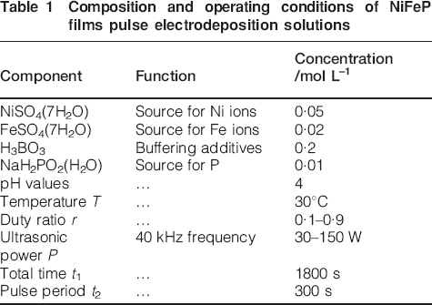
According to Table 1, NiSO4 and FeSO4 were chosen as the source of Ni and Fe ions respectively. H3BO3 served as a buffering additive to effectively and efficiently maintain stability of pH value. In addition, working temperature and pH value were kept to 30°C and 4 respectively. Duty ratio changed from 0·1 to 0·9, while power of ultrasonic (40 kHz frequency) ranged from 30 to 150 W during the pulse electrodeposition process to investigate the effects of r and P on NiFeP alloy films.
The acid solution was formed by adding proper amounts of chemicals into distilled water. A copper sheet with dimensions of 2×3 cm was selected as substrate for the NiFeP pulse electrodeposition process. The substrate was polished using a polishing machine (MP-1A) and dipped into alkaline solution (12 g L–1 NaOH, 60 g L–1 Na2CO3 and 60 g L–1 Na3PO4) to get rid of oils. H2SO4 (10%) solution was chosen to wipe off oxides. Finally, the copper was immersed into 100 mL electrolyte to perform an electrodeposition reaction for ∼30 min. A chart of the NiFe pulse electrodeposition process is shown in Fig. 1.
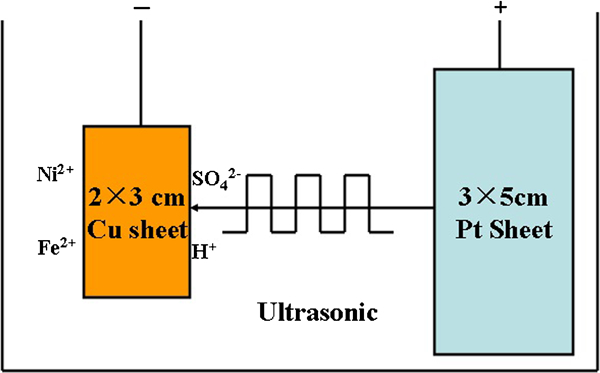
Chart of pulse electrodeposition process
After the electrodeposition was completed, NiFeP alloy film was washed with a jet of distilled water and dried using a blower. Microstructural analysis of the electrodeposited NiFeP films was carried out using an X-ray diffractometer (X'Pert Philips PW1830), which used a Cu Kα radiation as an incident beam and worked at 40 kV and 150 mA. The surface morphology of films was observed using an SEM (Hitachi S-4700) and an atomic force microscope (Asylum Research MFP-3D-SA). The composition of the films was analysed by EDX (EDX 1800B). Magnetic properties were tested by a vibrating sample magnetometer (Lakeshore VSM7407).
Results and discussion
Effects of different duty ratios on property of NiFeP films
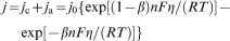
Metal ions possess certain equilibrium potential in the aqueous solution. As long as sufficient electrode potential is provided during the pulse plating process, metal ions would be reduced and deposited on the cathode. When certain electrode potential is given during the pulse plating process, anode and cathode reactions could happen simultaneously.6 The current density measured during the experiment is called macroscopic current density j, which is the sum of anode current ja and cathode current jc. The relationship between macroscopic current density and electrode potential is summarised below7
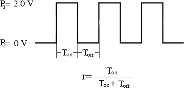
Sketch map of pulse electrodeposition process
Based on the definition of duty ratio, it is very clear that different duty ratios during pulse plating could affect the electrode potential duration. According to equation (1), changing of electrode potential would lead to different macroscopic current densities during the pulse plating process. During the electrodeposition process, the minimum current density is called lower limit, while the maximum current density is called upper limit. When the current density is lower than its lower limit, it is not possible to deposit metal coatings. If the current density is greater than the upper limit, deposited coating would be burnt and turn into black, which is mainly due to the precipitation of hydrogen near the cathode. Hence, this section investigated the effects of different duty ratios on deposition rate, composition and magnetic property of NiFeP films during the pulse plating process.
Duty ratios have an important role in deposition rate during the pulse plating process. Figure 3 gives the relationship between duty ratios and deposition rate. Based on Fig. 3, it was easy to get a conclusion that a higher duty ratio led to getting a larger deposition rate. With the rise in duty ratio, the deposition rate increased gradually. The relationship between duty ratio and deposition rate could be explained by Faraday's laws8

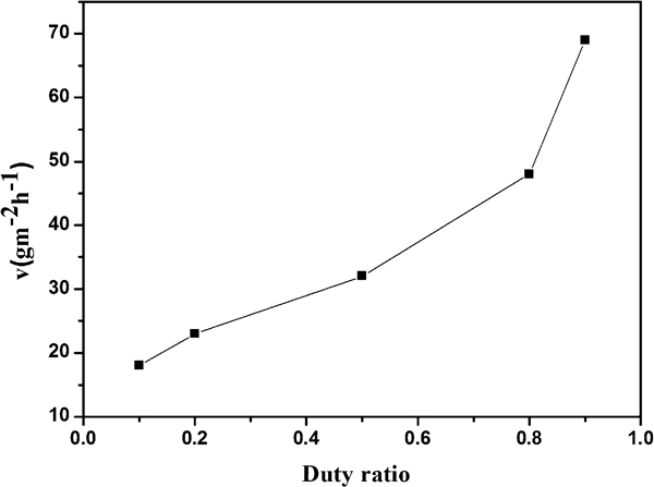
Effects of duty ratio on pulse electrodeposition rate: concentrations of NiSO4(7H2O), FeSO4(7H2O), NaH2PO2(H2O) and H3BO3 were 0·05, 0·02, 0·01 and 0·2 mol L–1 respectively (pH = 4, T = 30°C, P = 0 W, t1 = 1800 s and t2 = 300 s)
Energy dispersive spectroscopy was used to study different duty ratios on composition of NiFeP films during the pulse plating process. Figure 4 demonstrates the effects of duty ratios on composition of NiFeP alloy films.
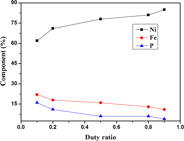
Effects of duty ratio on composition of NiFeP films: concentrations of NiSO4(7H2O), FeSO4(7H2O), NaH2PO2(H2O) and H3BO3 were 0·05, 0·02, 0·01 and 0·2 mol L–1 respectively (pH = 4, T = 30°C, P = 0 W, t1 = 1800 s and t2 = 300 s)
Different components of NiFeP films could be formed with the increase in duty ratios. According to Fig. 4, it was conspicuous that Ni contents in the film increased from ∼60 to 83% with the rise in duty ratio ranging from 0·1 to 0·9. However, the contents of Fe and P decline simultaneously, along with the increase in duty ratio. Chemical reaction rates during electrodeposition depend on potential control and diffusion control. During the pulse plating process, Ni reduction is potential controlled, while the Fe reduction is diffusion controlled.9 Hence, higher duty ratio during pulse plating could increase electrode potential duration, which induces higher Ni contents and lower Fe contents. NiFe codeposition phenomenon would mainly happen during Ton time. Because there was no potential introduced during Toff time, it was impossible to deposit iron or nickel. However, it was found that the main reaction occurs during the Toff time period as in the following

Effects of duty ratios on amount of phosphorus on NiFeP films
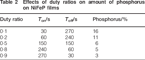
According to Table 2, it was clear that higher duty ratio could shorten Toff time, which induced the decline in amounts of phosphorus.
The effect of duty ratio on microstructure of NiFeP was studied by X-ray diffraction (XRD). X-ray diffraction patterns of NiFeP films pulse electrodeposited with different duty ratios are shown in Fig. 5. Based on the XRD patterns, three peaks of FeNi3 (111), FeNi3 (200) and FeNi3 (220) could be detected at 2θ = 43·5°, 2θ = 50° and 2θ = 74° respectively, which illustrated that the films were crystalline. The intensity of peak FeNi3 (111) was the strongest among the three peaks. Compared with standard powder diffraction cards, it was known that fcc FeNi3 was formed during the pulse plating process with different duty ratios. Debye–Scherrer equation was used to estimate the grain sizes of crystalline films

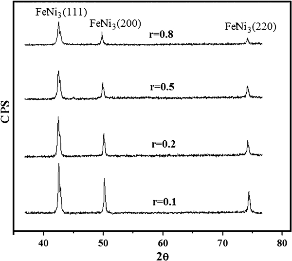
X-ray diffraction patterns of NiFeP films pulse electrodeposited by different duty ratios (FeNi3, JCPDS no. 65-3244): concentrations of NiSO4(7H2O), FeSO4(7H2O), NaH2PO2(H2O) and H3BO3 were 0·05, 0·02, 0·01 and 0·2 mol L–1 respectively (pH = 4, T = 30°C, P = 0 W, t1 = 1800 s and t2 = 300 s)
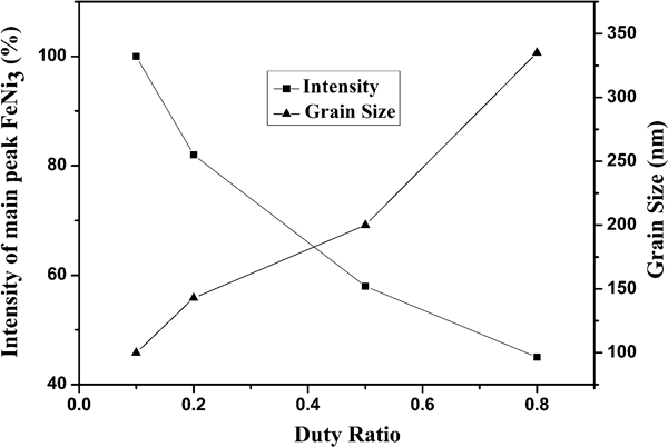
Relationship between duty ratios and grain size of films: concentrations of NiSO4(7H2O), FeSO4(7H2O), NaH2PO2(H2O) and H3BO3 were 0·05, 0·02, 0·01 and 0·2 mol L–1 respectively (pH = 4, T = 30°C, P = 0 W, t1 = 1800 s and t2 = 300 s)
Figure 7 demonstrates atomic force microscopy images of NiFeP films pulse electrodeposited with different duty ratios. According to Fig. 7, it was very clear that typical nodular and smooth films could be obtained by the condition of r = 0·1 during the pulse plating process. However, nodular granules started to grow bigger and agglomerate with the increase in duty ratio. In addition, rough surface of NiFeP films could be detected with the rise in duty ratio. It could be observed that the film prepared by pulse plating with r = 0·8 has bigger agglomerate with nodular structures and rough surface. Therefore, duty ratio could extremely affect the surface morphology of NiFeP alloys films. With the increase in duty ratios, the particles of film tend to grow bigger and form rough surfaces.
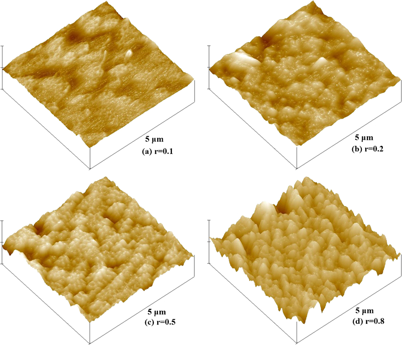
Effects of duty ratio on film surface morphology: concentrations of NiSO4(7H2O), FeSO4(7H2O), NaH2PO2(H2O) and H3BO3 were 0·05, 0·02, 0·01 and 0·2 mol L–1 respectively (pH = 4, T = 30°C, P = 0 W, t1 = 1800 s and t2 = 300 s)
The films pulse electrodeposited with various duty ratios showed different magnetic properties. Figure 8 demonstrates coercivity of films pulse electrodeposited with different duty ratios. It was clear that a higher duty ratio would induce a lower coercivity of NiFeP thin films. When duty ratio increased from 0·1 to 0·9, the coercivity decreased from 110 to 60 Oe. It was because that higher duty ratio led to lower phosphor contents in grain boundaries of NiFeP films, which contributes directly to the decline on coercivity.
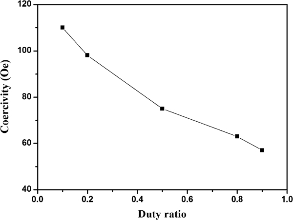
Effects of different duty ratios on coercivity of NiFeP films: concentrations of NiSO4(7H2O), FeSO4(7H2O), NaH2PO2(H2O) and H3BO3 were 0·05, 0·02, 0·01 and 0·2 mol L–1 respectively (pH = 4, T = 30°C, P = 0 W, t1 = 1800 s and t2 = 300 s)
Effects of different ultrasonic powers on property of NiFe films
In this section, ultrasonic was introduced during the pulse plating process for NiFeP films. Effects of different ultrasonic powers on electrodeposition rate, composition and surface morphology of films were investigated. Figure 9 gives the relationship between ultrasonic power and electrodeposition rate.
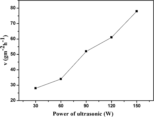
Effect of ultrasonic powers on pulse electrodeposition rate: concentrations of NiSO4(7H2O), FeSO4(7H2O), NaH2PO2(H2O) and H3BO3 were 0·05, 0·02, 0·01 and 0·2 mol L–1 respectively (pH = 4, T = 30°C, r = 0·5, t1 = 1800 s and t2 = 300 s)
Different ultrasonic powers could effectively affect electrodeposition rate during the pulse plating process. With regard to Fig. 9, electrodeposition rate increased gradually with the rise in ultrasonic powers. A deposition rate of 80 g–2 h–1 could be obtained when ultrasonic power was up to 150 W. A double layer is a structure that appears on the surface of the cathode during electrodeposition process. Double layer refers to two parallel layers of charge surrounding cathode. The first layer, the surface charge, comprises ions adsorbed directly onto the cathode. The second layer is made of free ions that move in the electrolyte under the influence of electric attraction and thermal motion. It is thus called the diffuse layer. First, ions move quickly towards cathode during Ton time (high potential). Second, because there was no potential introduced during Toff time (low potential), ions move towards cathode, relying on the function of thermal motion. Hence, electrical double layer could be formed during the pulse plating process because of changes at high potential and low potential interval. Double layer barrier formed during the pulse plating process could block and hinder ion transportation which decreased the deposition rate. Ultrasonic introduced during the pulse plating process could agitate the solution to increase the transportation of ionic species from bulk solution to electrode surface which greatly enhanced the deposition process. The effects of ultrasonic power on composition of NiFeP films are concluded in Fig. 10.
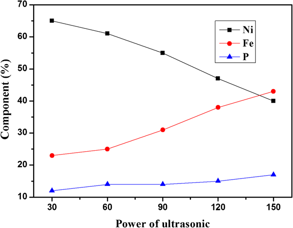
Effects of ultrasonic powers on composition of NiFeP films: concentrations of NiSO4(7H2O), FeSO4(7H2O), NaH2PO2(H2O) and H3BO3 were 0·05, 0·02, 0·01 and 0·2 mol L–1 respectively (pH = 4, T = 30°C, r = 0·5, t1 = 1800 s and t2 = 300 s)
Different components of NiFeP films could be obtained with the increase in ultrasonic powers. According to Fig. 10, with the increase in ultrasonic power, Ni contents declined gradually while Fe and P contents rose simultaneously. It was known that Fe reduction was diffusion controlled. Higher ultrasonic power would sharply agitate the solution to increase diffusion process during the pulse plating process, which was favourable for Fe deposition.10 Hence, higher ultrasonic power could induce larger Fe contents in the films. X-ray diffraction patterns were used to investigate the effects of ultrasonic power on microstructure of NiFeP films shown in Fig. 11.
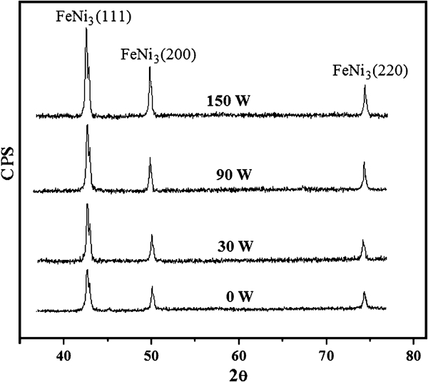
X-ray diffraction patterns of NiFeP films pulse electrodeposited by different ultrasonic powers (FeNi3, JCPDS no. 65-3244): concentrations of NiSO4(7H2O), FeSO4(7H2O), NaH2PO2(H2O) and H3BO3 were 0·05, 0·02, 0·01 and 0·2 mol L–1 respectively (pH = 4, T = 30°C, r = 0·5, t1 = 1800 s and t2 = 300 s)
Based on the XRD patterns, three peaks of FeNi3 (111), FeNi3 (200) and FeNi3 (220) could be detected at 2θ = 43·5°, 2θ = 50° and 2θ = 74° respectively. The intensity of peak FeNi3 (111) was the strongest among the three peaks. Compared with standard powder diffraction cards, it was known that fcc FeNi3 was formed during the pulse plating process with different ultrasonic powers. However, with the increase in ultrasonic power, the intensity of all three peaks started to increase which led to better crystalline and small grain sizes.
Images (SEM) were used to verify the conclusion drawn from XRD patterns. Figure 12 gives the effects of ultrasonic powers on surface morphology of NiFeP films during the pulse plating process. According to SEM images, the film presents typical spherical nodular structures without ultrasonic during the pulse plating process. With the increase in ultrasonic power, relatively smaller and nodular shaped crystallites were observed when the films were pulse electrodeposited under ultrasonic power of 90 W. It was very obvious that higher ultrasonic power introduced during the pulse plating process would smash the particle sizes and lead to form a much denser and smoother surface. However, many cracks appeared at the surface of the film, when the power of ultrasonic was up to 150 W, which could reduce the cohesion force of films. Hence, NiFeP films pulse electrodeposited by the condition of higher ultrasonic power would possess denser and smaller nodular structure. However, too much higher ultrasonic power could result in cracks and reduce cohesion force.
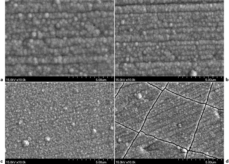
Images (SEM) of NiFeP thin films electrodeposited under different ultrasonic powers: concentrations of NiSO4(7H2O), FeSO4(7H2O), NaH2PO2(H2O) and H3BO3 were 0·05, 0·02, 0·01 and 0·2 mol L–1 respectively (pH = 4, T = 30°C, r = 0·5, t1 = 1800 s and t2 = 300 s): a 0 W; b 30 W; c 90 W; d 150 W
The films pulse electrodeposited with various ultrasonic powers showed different magnetic properties. Coercivity of films pulse electrodeposited with different ultrasonic powers is illustrated in Fig. 13. Obviously, higher ultrasonic powers introduced during the pulse plating process would induce larger coercivity of NiFeP thin films. When ultrasonic power increased from 30 to 150 W, the coercivity rose from 105 to 155 Oe. It was because that higher ultrasonic power resulted in abundant phosphor contents in grain boundaries of NiFeP films and small grain sizes, which contributes directly to the rise in coercivity.
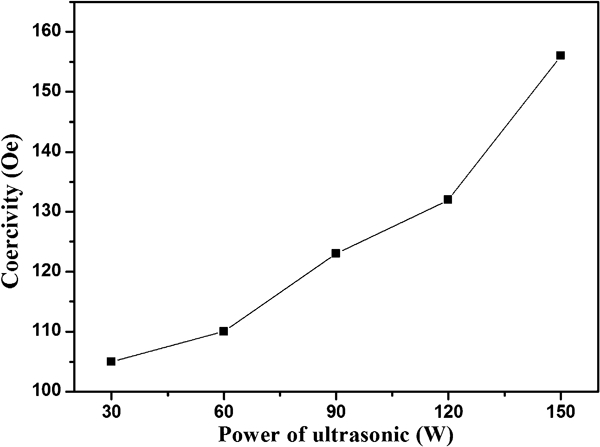
Effects of different ultrasonic powers on coercivity of NiFeP films: concentrations of NiSO4(7H2O), FeSO4(7H2O), NaH2PO2(H2O) and H3BO3 were 0·05, 0·02, 0·01 and 0·2 mol L–1 respectively (pH = 4, T = 30°C, r = 0·5, t1 = 1800 s and t2 = 300 s)
Conclusion
Ultrasonic was introduced during the pulse plating process to prepare NiFeP alloy films. Effects of different duty ratios and ultrasonic powers on composition, microstructure and magnetic properties of films were investigated. The following conclusions have been drawn.
With the increase in duty ratios, higher current density could result in the rise in the mass of the substance liberated at an electrode, which contributes directly to the increase in deposition rate. Ni contents in the film increased from about 60% to 83% with the rise in duty ratio ranged from 0·1 to 0·9. Duty ratio could extremely affect the surface morphology of NiFeP alloy films. With the increase in duty ratios, the particles of film tend to grow bigger and form rough surface. When duty ratio increased from 0·1 to 0·9, the coercivity decreased from 110 to 60 Oe.
Higher ultrasonic powers could extremely increase electrodeposition rate during the pulse plating process. Larger iron contents of NiFeP alloy films could be obtained with the rise in ultrasonic power. Almost all the deposited films were crystalline and formed peaks of FeNi3 (111), FeNi3 (200) and FeNi3 (220). NiFeP films with smaller grain size and smooth surface could be obtained when higher power of ultrasonic was introduced during the pulse plating process. Higher ultrasonic powers introduced during the pulse plating process would induce larger coercivity of NiFeP thin films. When ultrasonic power increased from 30 to 150 W, the coercivity rose from 105 to 155 Oe.
Footnotes
Acknowledgements
This work is supported financially by the Natural Science Foundation of ZheJiang Province (grant no.Y4110290).