
Abstract
X-ray diffraction (XRD) techniques including stress measurement were applied to untreated, low temperature plasma nitrided and low temperature plasma carburised AISI 304 austenitic stainless steels treated at 425°C for 12 h in H2/N2 and H2/CH4 gases respectively. Relationships between surface microhardness and XRD peak broadening were established. The results also showed that both surface treated layers were under a compressive residual stress. The compressive residual stresses of the low temperature plasma nitrided and the low temperature plasma carburised layers were 2·19 and 1·58 GPa.
Keywords
Introduction
The application of austenitic stainless steels is restricted by their relatively low surface hardness and hence their limited fatigue and wear resistance. However, the introduction of interstitial atoms such as nitrogen (N) and/or carbon (C) into the surface of stainless steels can significantly increase surface hardness, leading to improved fatigue and wear performance. Conventional plasma thermochemical surface engineering processes at high temperatures (>500°C) generate the formation of hard iron–chromium nitrides or carbides in the surface layer. Surface modification processes carried out at low temperature ranges (<500°C) can also improve the surface mechanical properties but without the formation of these hard compounds and thus avoiding the depletion of chromium from the matrix. The surface alloyed layers produced by treatment in the lower temperature range therefore not only show improvements in wear and fatigue resistance but also retain the high corrosion resistance of stainless steels.1, 2
The surface alloyed layers produced at low temperatures appear as dense, white, precipitate free structures and they are supersaturated with interstitial solid solution of nitrogen and/or carbon.3 They consist of a single phase having a unique X-ray diffraction (XRD) pattern where diffraction peak positions deviate markedly from the expected theoretical positions of common Bravais lattices.4 The XRD pattern is similar to that of a face centred cubic (fcc) austenitic structure, but the peak positions are at lower diffraction angles and the reflections contain both broadening and asymmetry.5 The crystallographic nature of this phase is open to debate and hence has been described in a number of ways. The designations ‘expanded/supersaturated austenite’, ‘γN’ and ‘S phase’ refer to an austenitic (fcc) crystallographic structure, while ‘m phase’ refers to a body centred tetragonal structure.4 A face centred tetragonal structure is also suggested.4 The term ‘low temperature colossal supersaturation’ has also emerged recently from the USA.2
Although both nitrogen and carbon occupy the same interstitial lattice positions, the supersaturation by nitrogen is much higher than for carbon.6 However, the diffusion of carbon is much faster than nitrogen, resulting in thicker layers for the same treatment time and temperature.6 Mechanical properties such as surface microhardness and fatigue resistance are significantly improved by both nitrogen and carbon surface alloyed layers. There are small differences between the microhardness levels of the nitrogen and carbon surface alloyed layers: the nitrogen tends to give higher surface hardness with a slightly brittle surface while the carbon gives slightly lower surface hardness. The levels of plain and fretting fatigue resistance are quite similar for both surface alloyed layers.3
Surface modification processes generally increase the case depth or hardness and may encourage a residual stress distribution, producing the longest component life.7 Internal stress is an extrinsic property and must be calculated via a directly measurable property such as strain, hence the normal method of residual stress determination is to calculate stress from strain, assuming linear elasticity,7 using XRD to measure d spacing of suitable lattice planes in the structure under investigation.
The purpose of this study is to analyse and compare the residual stresses in the nitrogen and carbon surface alloyed layers produced by low temperature plasma nitriding and low temperature plasma carburising processes on AISI 304 austenitic stainless steels using the same treatment time and temperature. Microlattice strains were measured using XRD techniques and the residual stresses were then calculated.
Experimental
AISI 304 austenitic stainless steel [Fe–18·95Cr–9·39Ni–1·56Mn–0·68Si–0·03P–0·04S (wt-%)] disc samples, 6 mm in thickness, were cut from 25·4 mm diameter bar supplied in the hot rolled condition. The flat surfaces of the disc samples, top and bottom, were manually ground with silicon carbide grinding papers (120, 360, 600, 800 and 1200 respectively), then degreased with degreasing agent, water rinsed, cleaned with acetone and dried with hot air. The samples were divided into three groups of five discs and marked as untreated, nitrogen (for low temperature plasma nitrided) and carbon (for low temperature plasma carburised). The untreated samples were kept for characterisation without any further treatment. The low temperature plasma nitrided samples were put in sample holders and treated in a 75%H2/25%N2 gaseous atmosphere using an automatically controlled 60 kW Klöckner DC plasma nitriding unit at 425°C for 12 h. The plasma carburised samples were also put in the sample holders but processed in a 98%H2/2%CH4 gas mixture utilising a manually controlled 40 kW Klöckner DC plasma unit at 425°C for 12 h. The half circular shape sample holders of 6 mm in thickness AISI 304 stainless steel with five drilled holes of 25·4 mm in diameter were designed to position each set of five disc samples in a perpendicular position relative to the plasma unit floor in order to treat both of the flat sides of the sample surfaces and to eliminate the nitriding ring effect. Treatments were conducted in separate vacuum/plasma units in order to avoid contamination of surface alloying elements. No further mechanical polishing was performed after the treatments.
Phase identification, peak shift and peak broadening analysis were performed on both untreated and treated samples using the focused beam XRD method on a 18 kW Rigaku TTRAX III X-ray diffractometer at 50 kV and 300 mA (15 kW) with a standard attachment, a copper Kα (Cu Kα ) radiation (wavelength: 1·540562 Å) rotating anode and a nickel (Ni) filter. The diffraction pattern was obtained via a scanning axis of 2θ/θ with a continuous scan mode, a scan speed of 1° min−1 (of 2θ) and start–stop angles of 20–100°.
Residual stress measurements of the samples were also obtained using the 18 kW Rigaku TTRAX III X-ray diffractometer operated at 50 kV and 300 mA (15 kW) fitted with a stress measurement attachment (the multipurpose attachment 3 for stress), a Cu Kα rotating anode and a Ni filter by application of the parallel beam XRD and residual stress (side inclination) methods. By this means, samples could be tilted to set ψ angles for the inclined measurement. The applied ψ angles were 0, 5 and 10°. Continuous scan mode measurement was used with a scan speed of 1° min−1 (of 2θ) and start–stop angles of 82–96°. Strains in the crystal lattice were then used to calculate the surface residual stresses by assuming bulk and a linear elastic distortion of the crystal lattice.7 Elastic modulus E and Poisson's ratio ν obtained from four point bending tests of AISI 304 sheet according to ASTM E1426-98 were used to determine the effective elastic parameter for XRD measurements of the residual stresses.
Surface microhardness was measured on the surface of both coated and uncoated AISI 304 samples using a Vickers microhardness tester with an applied load of 10 g.
Results and discussion
Phase identification
Figure 1 shows the XRD patterns of untreated and treated AISI 304. A typical set of fcc peaks of austenite phase γ was obtained for the untreated AISI 304 sample. Two similar patterns but with broad peaks that were displaced to lower Bragg (2θ) angles relative to the corresponding peaks for the untreated sample were obtained from the nitrogen and carbon alloyed surface layers. The structure of these layers has been variously described as expanded austenite,6, 8 supersaturated austenite or S phase.9 The two sets of peaks were designated as γN and γC respectively. The degree of peak shift is higher for nitrogen. Peak asymmetry and a decrease in peak intensity were observed. A study by Sun et al.9 suggested that the low temperature nitrided layer has an fcc structure, which is highly disordered and distorted, due to the formation of stacking faults (confirmed later by Christiansen and Somers4) with high compressive residual stresses in the nitrided layer. The presence of stacking faults in fcc lattices can influence not only the profiles (peak broadening) but also the positions (peak shift) of the XRD peaks.9 The residual stress in the material can also result in a peak shift for which the degree of peak shift depends on the stress level σ and the elastic constant S of the diffracting plane.9 Stacking faults in fcc lattices also lead to a decrease in the peak intensity of the XRD patterns and their effects have been explained with respect to deformation α and twin stacking fault densities β using fault induced scattering geometry in diffraction in an imperfect crystal by Warren's theory and Wagner's method.5
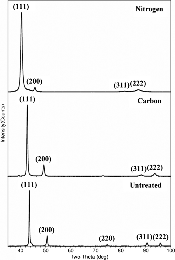
X-ray diffraction pattern of untreated, carbon and nitrogen surface alloyed layers
Peak shift and broadening evaluation
As mentioned earlier in the section on ‘Phase identification’, peak shift and broadening of untreated and treated AISI 304 can be identified in the XRD patterns shown in Fig. 1. Line broadening data related to peak shift and broadening of untreated and treated AISI 304 are listed in Table 1. Breadth is expressed as the total area under the peak divided by diffraction peak height. Breadth provides information on the size (distribution) of diffraction domains and the content of crystalline defects such as dislocations and stacking faults.10 The breadth of the X-ray line often correlates with the hardness of the material. The surface microhardness values of untreated, carbon treated and nitrogen treated surface alloyed layers were 200, 700 and 1200 HV0·01 respectively. The peak breadth data of untreated, carburised and nitrided AISI 304 are in ascending order (untreated<carburised<nitrided) for all reflections. There is a relationship between microhardness and peak half-width [full width at half maximum (FWHM)], as FWHM data of untreated, carburised and nitrided AISI 304 are also in ascending order (untreated<carburized<nitrided). Plots of surface microhardness versus peak breadth and FWHM measured at (222) are shown in Fig. 2.
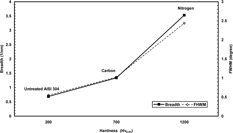
Plots of hardness (HV0·01) versus breadth and FWHM
Peak broadening data of untreated, carbon and nitrogen alloyed surface*
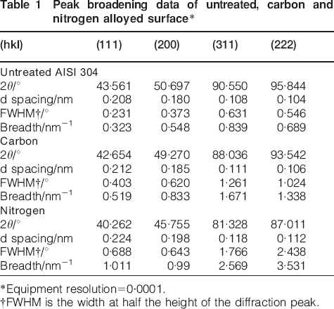
Equipment resolution = 0·0001.
†FWHM is the width at half the height of the diffraction peak.
Residual stress calculation
According to Fitzpatrick et al.11 and Cullity,12 different crystallographic planes vary in their deformation mechanisms and give different responses for both elastic (residual stress) and inelastic strain (line broadening), thus measurements made on different crystallographic planes or made with different radiations are generally not comparable. It is suggested that the reflection with the highest multiplicity should be selected if the sample is textured or has a large grain size as this may reduce oscillation in the sin2 ψ plot.
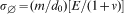
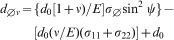
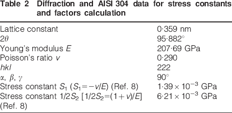
In this study, the highest multiplicity plane within the limit of the XRD equipment used was (222). There was no further information at 2θ values >100° for the treated samples. Residual stresses can be calculated from measured data of lattice strain for the (222) plane at different angles ψ by the XRD residual stress method and by assuming that the errors due to instrument effects are eliminated. Linear plots of d222 versus sin2 ψ along with linear plots of 2θ versus sin2 ψ of nitrogen and carbon alloyed surface are presented in Figs. 3 and 4 respectively. Slopes (Fig. 3) and stress constant (Table 2) are used in the following equations for residual stress calculation12
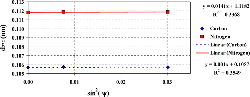
Linear dependence of d222 upon sin2 ψ for carbon and nitrogen surface alloyed layers
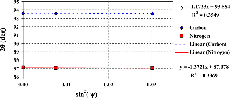
Linear dependence of 2θ versus sin2 ψ for carbon and nitrogen surface alloyed layers
Diffraction and AISI 304 data for stress constants and factors calculation
Finally, the residual stress levels in the nitrogen treated and carbon treated layers were determined as 2·19 and 1·58 GPa respectively. These results are in agreement with Sun and Chin13 whose results showed that the carbon S phase layers are under a compressive residual stressed condition, to a level between 1·5 and 3·5 GPa.
Conclusion
Both the low temperature plasma nitriding and the low temperature plasma carburising processes induced high compressive residual stresses in the surface of AISI 304 austenitic stainless steel due to supersaturation of austenite by interstitial nitrogen and carbon atoms. Residual stress measurements from XRD revealed compressive residual stress levels of 2·19 and 1·58 GPa on the surface of nitrided and carburised AISI 304 respectively.
Footnotes
Acknowledgements
The authors are thankful for the financial support provided by the National Metal and Materials Technology Center, Thailand (MT-B-52-MET-07-218-I) and the revision of the XRD experimental results and manuscript draft by Mr Suparoek Henprserttae and Dr John Thomas Harry Pearce.