
Abstract
The post-treatment of ion implantation on hard coatings attracts a great deal of attention because of the improvement in coating surface properties. The present research investigates the effect of nitrogen (N), carbon (C) and carbon followed with nitrogen (C+N) ion implantations on the structural and mechanical properties of the Ti–Al–Si–N coatings. Ion implantations were performed at an energy of 50 keV and different doses. The surface properties of the implanted layer were identified by a variety of analytic techniques, such as cross-sectional transmission electron microscopy, energy dispersive spectroscopy, Raman spectroscopy, X-ray photoelectron spectroscopy and nanoindentation measurement. Additionally, the wear performance of the samples was evaluated by a typical ball on disc tribometer in dry conditions. The results showed that the surface properties depended strongly on the implanted species and doses. In addition, a great improvement in the wear was observed on the samples with the post-treatment process of C and C+N ion implantations.
Introduction
The development and application of hard coatings to cutting tools have led to dramatically extended tool life and the realisation of high speed machining. In the past decades, transition metal nitride coatings have been shown to be particularly promising for use in the machining industry owing to their high hardness (20–30 GPa), melting point, chemical inertness and good thermodynamical stability.1 – 3 The recent coating development has been turned towards the design of ternary or quaternary nitride since higher hardness can be realised. Since the recent introduction of TiAlSiN coatings, TiAlSiN coatings are expected to be an excellent candidate for use in the modern machining industry due to its high hardness, good thermal stability and extreme oxidation resistance. 4 4,5 However, the friction coefficients of the hard coatings are still high (about 0·4–0·9) in dry sliding.6 The need for low friction to facilitate chip removal, particularly in drilling without coolant participation, has promoted researches into the use of solid lubricating coatings on top of the hard coatings. Improvement in the service lifetime of the cutting tools has been generally observed for depositing solid lubricating MoS2, WC/C and a-C coatings onto a single hard coating of TiN, CrN and TiAlN. 7 7,8
Ion implantation is found to be an alternative method to modify surface properties without damaging the originally excellent properties (e.g. high hardness) of the coatings. Many studies have been carried out on the effect of the implantation of noble gas ions (Ar+, Kr+ and Xe+), 9 9,10 metal ions and carbon (C) and nitrogen (N) ions into TiN in the field of mechanical manufacture.11 – 13 In all of the aforementioned works, the post-treatment of N and C ion implantation has been shown to considerably improve the mechanical properties and the tribological behaviour of hard nitride coatings, yielding increased wear resistance and lifetime.
It is believed that the post-treatment process of N and C implantation on the TiAlSiN coating can also improve the friction and wear performance of the coatings. To our knowledge, no attempts have been made on the study about the effect of N or C ion implantation on the surface and tribological properties of the coatings. This investigation focused on the structural, mechanical and, particularly, tribological properties of TiAlSiN coatings post-treated by high energy N or C ion implantation.
Experimental
TiAlSiN coatings with a typical thickness of 1·5 μm were deposited onto hardened M2 high speed steel and Si substrates by reactive close field unbalanced magnetron sputtering system (Teer UDP-450) with a high purity of Ti, Al and Si targets. In order to increase the adhesion of the coating, a Ti buffer layer was first deposited. By optimising the deposition conditions, TiAlSiN coatings [39 at-%Ti, 11 at-%Al, 4 at-%Si and 46 at-%N, determined by X-ray photoelectron spectroscopy (XPS)] with sufficient adhesion (scratch critical load, >70 N) and hardness (31·2 GPa) were obtained. In this study, carbon ion implantation was performed using a metal vapour vacuum arc ion source. The implantation was carried out in a broad beam, line of sight mode. The N and C ion energies during implantation were fixed at 50 keV. The 50 keV was chosen because the atom sizes of nitrogen and carbon are almost the same, and the expected projected ranges of the two ions in the TiAlSiN coatings are very close, i.e. ∼120 nm (from TRIM software).14 In this study, three sets of samples (A, nitrogen; B, carbon; and C, carbon followed with nitrogen) were prepared with different ion doses. Details can be found in Table 1. All the implantations were carried out under a vacuum level of ⩽2·7×10−4 Pa. The sample temperature rise during implantation was below 200°C.
Summary of parameters of implantation into TiAlSiN coatings and tribological properties of implanted samples*
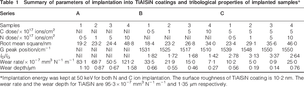
Implantation energy was kept at 50 keV for both N and C ion implantation. The surface roughness of TiAlSiN coating is 10·2 nm. The wear rate and the wear depth for TiAlSiN are 95·3×10−7 mm3 N−1 m−1 and 1·35 μm respectively.
The cross-sectional TEM images were obtained using a JEOL JEM-2010F field emission electron microscope operated at 200 kV. The chemical bonding states of the implanted coatings were analysed with XPS (PHI Quantum 2000) combined with 2 keV Ar+ ion beam scanning over 1×1 mm. Raman spectroscopy was used to characterise the bonding structure of the implanted samples using an Ar+ laser operated at 514·5 nm at a power of 20 mW. The hardness of the samples was examined by a nanoindentation apparatus (Hysitron) interfaced with an atomic force microscope that the in situ imaging could eliminate the surface roughness effect during indentation. Indentations were made by a trigonal (Bekovich) diamond tip with a tip roughness of ∼300 nm using a single loading–unloading cycle. The analysis of nanoindentation data followed the approach of Oliver and Pharr.15 In order to obtain the outmost surface hardness, a tiny indentation load of 800 μN was applied, by which the indentation depth was limited below 40 nm. Indentations were repeated at least 10 times in order to get a mean value. The surface images of the samples were obtained by atomic force microscopy (AFM) (Auto-Probe CP; Park Scientific Instruments) with a force sensor operated in contact mode. The wear behaviour of the samples was evaluated by a ball on disc tribometer at a sliding speed of 0·1 m s−1 against WC–6 wt-%Co balls in a dry condition. The tests were performed using a normal load of 5 N. In all the tests, the duration of sliding wears lasted for 6000 cycles. Measurements were carried out at room temperature with a relative humidity of ∼60%.
Results and discussion
Ion implanted layer
Generally, an implanted layer is generated on the coating's surface, where the ions come to rest directly beneath the surface, after the ion implantation process. The thickness of the implanted layer depends on the implantation doses. Figure 1 shows the typical cross-sectional TEM images of sample B4. It can be found from the figure that a thin implanted layer (A) can be easily indentified on the surface of the bulk coating. The layer thickness is ∼220 nm. As determined by the contrast of the TEM images, it was found that increasing the implantation doses leads to an increase in the implanted layer thickness, which varied from 150 to 230 nm. The thickness of the top layer appeared to agree well with the values predicted by TRIM software. A linescan by energy dispersive spectroscopy on the cross-sectional image confirmed the presence of the incoming ion species. At a depth of 100 nm from the coating's surface, ∼70 at-%C was present for sample B4.
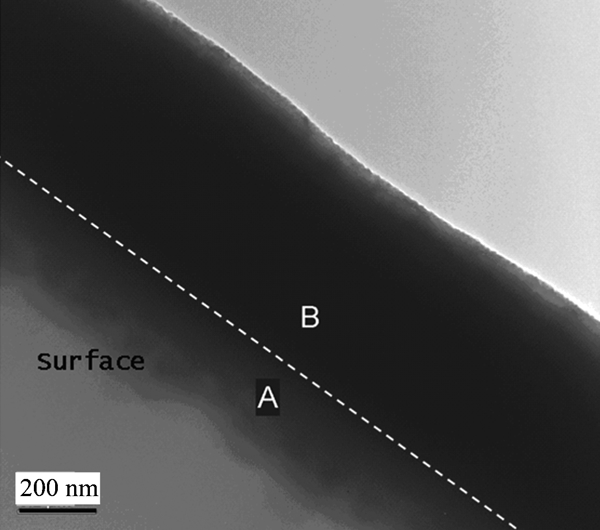
Cross-sectional TEM images of sample B4: A represents ion implanted top layer, while B represents bulk coating
Surface roughness
The surface roughness, root mean square, of the samples measured by AFM is summarised in Table 1. Generally, the surface roughness increases with increasing ion doses by either N, C or C+N ion implantation. Figure 2a and b shows the AFM images of samples B1 and B4. As shown, the morphology appears to be a set of continuous mounds that become larger and less irregular as the C ion dose increases. The corresponding linescans of sample B1 exhibited diameters of the mounds of ∼50 nm and a height of up to 20 nm, while the diameter and height of the nuclei of sample B4 increased to ∼200 and 20 nm respectively. This behaviour is mainly due to the effect of the bombardment of high energetic ions and the induced resputtering and ion implantation processes.
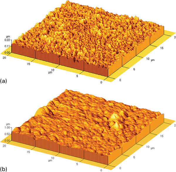
Typical AFM topography images of sample implanted (a) with a lower dose (B1), and (b) with a higher implantation dose (B4)
Hardness
The relative hardness ratios of the samples to the TiAlSiN coating are shown in Fig. 3. For series A, the hardness of the TiAlSiN coatings increases slightly with N ion doses. The largest hardening effect (∼10%) was found for ion dose of 5×10¹⁷ N+ ions/cm2. However, a further increase in N ion dose would lead to a decrease in hardness. In this study, the optimal ion implantation is ∼5×10¹⁷ N+ ions/cm2, which is basically consistent with the results observed by other groups. 11 11,16 Jang and Lee16 observed that the effect of nitrogen implantation is optimal at 3×10¹⁷ N+ ions/cm2; lower doses have little effect, but higher doses lead to a softening of the surface. The increase in hardness can be attributed to conventional radiation induced effects such as dislocation hardening. 11 11,17
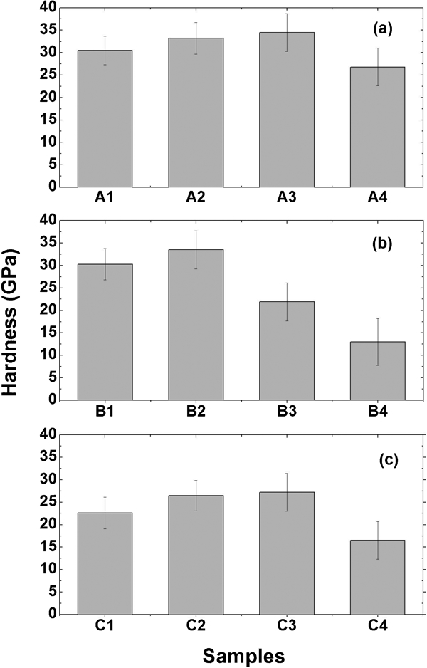
Variation in hardness of samples: nanoindentation was performed at indentation load of 800 μN: (a) pure N implantation; (b) pure C implantation; (c) C+N implantation
For series B, the indentation results reveal that the hardening effect (∼10%) is found on the sample implanted with 1×10¹⁷ C+ ions/cm2 (sample B2). However, an increase in the carbon ion doses will lead to a significant decrease in hardness. Specifically, the hardness drops almost 30 and 60% for samples B3 and B4 respectively. Normally, the presence of new phases can give an increase in the coating hardness compared with titanium nitrides. 11 11,18 Figure 4a and b shows the C1s core level spectra of samples B2 and B4. As shown, sample B2 existed in two forms (Ti–C and C–C); whereas, only one form (C–C) was found for sample B4 at an etching depth of 100 nm from the surface. Therefore, the formation of carbide bonds (e.g. Ti–C or Ti–C–N) as indicated from the XPS can be reasonably attributed to the increase in hardness recorded for the samples implanted with lower implantation doses. On the contrary, the reduction in hardness with higher implantation doses is mainly due to the substantial amount of amorphous or graphitic carbon built on the coating surface.
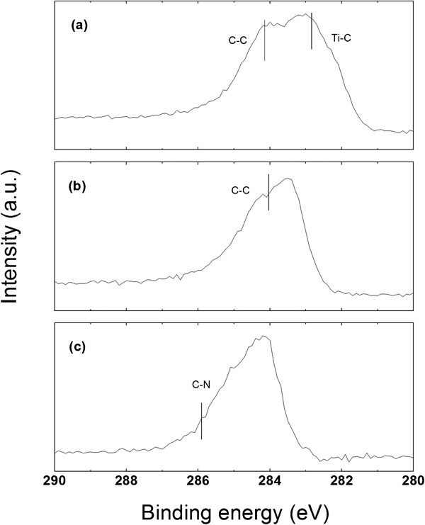
Spectra (XPS) obtained from C1s region at etching depth of ∼100 nm: a sample B2; b sample B4; c sample C3
For series C, the N ion implantation into the C implanted TiAlSiN coatings, the increase in ion doses leads to an increase in hardness from 21·9 to 26·5 GPa. However, a further increase in the N ion doses will cause a decrease in hardness to 16·5 GPa. The examination of the samples by Raman showed that when the N implantation doses increased, the sp2 phase and the sp2 carbon cluster size increased, as indicated by the increase in the ID/IG ratio and the increase in Raman spectra intensity (see Table 1). Meanwhile, nitrogen atoms were bound to carbon atoms, as forming C–N (see Fig. 4c). Therefore, the increase in hardness of series C can be explained by the promotion of the sp2 phase and sp2 clusters, resulting in the increase in sp2 C–C and sp2 C–N in carbon networks. 19 19,20
Tribological performance
The variations in friction coefficient of the samples as a function of sliding cycles against WC–6wt-%Co balls are shown in Fig. 5. As shown in Fig. 5a, the friction coefficient of the TiAlSiN coating at a sliding load of 5 N exhibits a friction coefficient of ∼0·6 on the whole wear process. The value is in good agreement with the results reported by other groups. 21 21,22 In this study, the post-treatment of the ion implantation process on the TiAlSiN coatings can generally lead to a decrease in the friction coefficient. The friction coefficient decreases with nitrogen ion doses (see Fig. 5a). It is more obvious for series B and C. Remarkedly, the friction coefficient reached 0·1 for the sample implanted with the highest carbon doses (sample B4). The value is similar to that observed for magnetron sputtered carbon coatings.23 In addition, an extremely low friction coefficient (0·07) was achieved for sample C3. The friction coefficient was very stable and kept very low until the end of the test. However, if the implantation doses for series A and C are larger than the critical value (both are 5×10¹⁷ ions/cm2), the friction coefficient increases sharply to ∼0·5 after the initial few hundreds of sliding cycles (see samples A4 and C4).
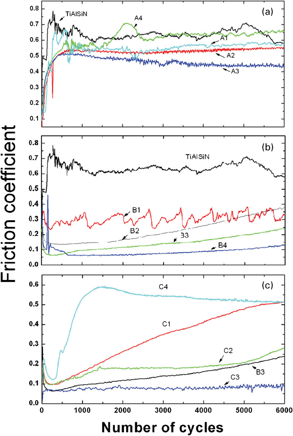
Variation in friction coefficient of samples at sliding load of 5 N: (a) pure N implantation; (b) pure C implantation; (c) C+N implantation
Figure 6 shows examples of SEM and three-dimensional images of the samples. As can be seen, the ion implanted TiAlSiN coatings exhibit a smoother and more homogeneous wear. No obvious abrasive scratches can be observed on the wear track. Moreover, the wear width and depth are also decreased. Better wear improvement can be found on the C and C+N implanted samples. For the cases of B4 and C3, the wears were restricted to the outmost few hundreds of nanometre surface, in which the implanted layer provided low friction and ensured good stability on the whole sliding process. After 6000 sliding cycles, we only found polish of the surface asperity sample C3, which indicated the excellent antiwear property of the sample.
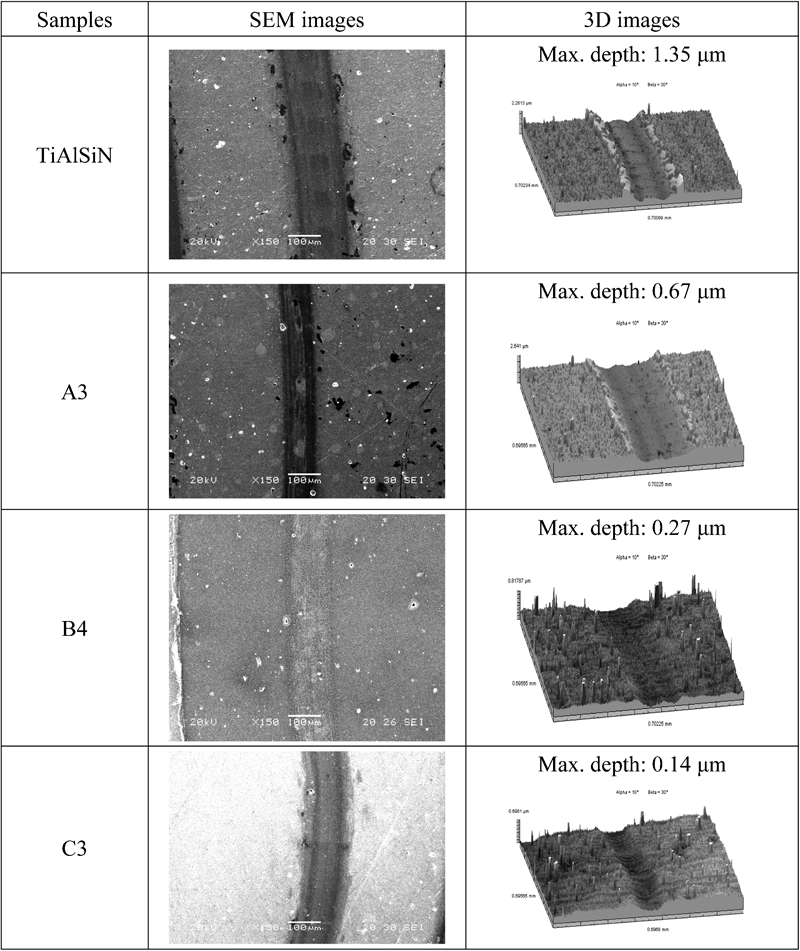
Scanning electron microscopy and three-axis images showing comparison of wear morphology of samples after wear tests at sliding load of 5 N after 6000 cycles
The wear volume of the samples was measured by profilometer method, and the specific wear rate of the samples can be found in Table 1. It can be found that the post-treatment of the ion implantation process can lead to a better wear resistance of the TiAlSiN coatings, except for sample A4.
For series A, the wear rate of the samples decreases with ion dose. However, after an optimal value of 5×10¹⁷ N+ ions/cm2, the wear rate increases, and the wear rate is larger than the original TiAlSiN coating. Actually, the wear rate follows the same trend of hardness as observed in the nanoindentation tests. The maximum wear resistance corresponding to the nitrogen dose provides the maximum hardening effect. In this study, abrasive wear is the main wear mechanism for the nitride coatings against hard rubbing bodies. Increasing the surface hardness of the TiAlSiN coatings can effectively reduce the wear loss during the wear process. Therefore, the changes in the level of abrasive wear for samples A1–A3 can be attributed to the hardening induced by N ion implantation, and the decrease in wear resistance for sample A4 can be understood based on the softening upon surface amorphisation after an optimal value of implantation dose.
For series B, it can be found that the wear rates show a direct relationship with the carbon ion doses. The sample implanted with maximum carbon ion dose exhibits the smallest wear loss, with an order of magnitude lower than the unimplanted one. The greatly improved wear performance of the C implanted samples can be explained by the reduction in Ti and Al contents on the outmost surface and the formation of the graphitic phase. Under the wear conditions used, the oxide layer (Al2O3), induced by flash temperature, cracks, and subsequently rubs off, resulting in the degradation of the TiAlSiN surface in an abrasive manner. The decrease in the Ti and Al contents on the top layer of the coatings can change the wear mode and reduce the abrasive wear to a great extent. Meanwhile, the implanted C ions stay in graphitic form with the structure characteristics approaching a-C coatings after the implantation process, which can be evidenced by XPS and Raman analyses. Therefore, the layer can provide a lubricating effect, resulting in friction and wear reduction.
Increasing the N implantation dose can increase the wear resistance of the C implanted TiAlSiN coatings, peaking at 5×10¹⁷ N+ ions/cm2 dose. Under such post-treatment process, the coating exhibits a wear rate of 0·85×10−7 mm3 N−1 m−1, which is two orders of magnitude lower than the TiAlSiN coating. Basically, the improved wear mechanism for the C+N implanted samples is similar to the C implanted samples. However, the lower wear rate is supposed to be associated with the presence of a higher content of highly disordered carbon clusters after the N ion implantation. As mentioned above, the samples implanted with higher N doses exhibit an increased number and size of the graphitic domains. Meanwhile, the implantation process leads to the formation of the C–N phase, which is most likely present in sp2 form. It is well known that the wear resistance of a material surface can be greatly increased by the introduction of a-C and C–N coatings.24 In this case, the low friction coefficient in the implanted sample obeyed the same mechanism as that in a-C or C–N coating. Therefore, the low friction coefficient of the implanted layer can be attributed to the formation of a thin sp2 C–C or C–N layer, which promotes the graphitisation process during sliding and thus reducing the friction and wear in consequence. On the contrary, the slight increase in wear rate after the optimal value of N implantation dose (sample C4) may be probably due to the decrease in hardness and, particularly, the implantation enhanced brittleness of the implanted layer. As shown in Fig. 5, the implantation layer has been worn out quickly after 1000 cycles, indicating a direct sliding contact between the counterface and the TiAlSiN coatings on the remaining sliding process. Normally, residual stress, either tensile or compressive depending on whether vacancy generation and atom peening effects dominate, will be built on the surface.25 It is believed that the implantation process, particularly for the high implantation cases, will alter the stress level on the ion implanted zone, leading to a surface with higher brittleness and poorer wear resistance.
Conclusion
The surface properties and the tribological performance of TiAlSiN coatings post-treated by N, C or C+N implantation at a high energy by metal vapour vacuum arc have been studied. The results showed that the coatings with appropriate amount of implantation doses exhibited an improvement in tribological performance in terms of friction coefficient and wear rate. Remarkedly, the improvement in the coatings was more significant for the cases of C and C+N implantations, in which there are 1 and 10 orders of magnitude respectively of improvement of the coatings at an optimal value of implantation dose. The friction coefficient of the samples could be reduced from 0·6 to <0·1. The improved tribological performance of the coatings with ion implantation processes could be explained by changes of the mechanical properties (series A), formation of graphitic C–C bonds (series B) and formation of sp2 C–N clusters (series C). It is expected that the greatly enhanced wear property of the Ti–Al–Si–N coatings can expand this coating to be used in a wider range of modern industries, where manufacturing reliability and productivity are important.
Footnotes
Acknowledgements
The work described in this paper was fully supported by the GRF (grant no. CityU116807) from HKSAR Research Grant Council.