
Abstract
Sol–gel derived organic–inorganic hybrid coatings have been investigated as a potential replacement for the environmentally hazardous chromate conversion coatings for corrosion protection of aerospace aluminium alloy AA 2024. Sol–gel hybrid coatings were prepared using a sol mixture (1∶1 volume ratio) of 3-glycidoxypropyl trimethoxysilane and tetraethoxysilane and doped with cerium nitrate and deposited on AA 2024 by dip coating and spray coating techniques. The effect of surface pretreatment on the corrosion protection efficiency of the sol–gel hybrid coatings was studied. The corrosion resistance of the coatings in 3·5% sodium chloride solution was evaluated by potentiodynamic polarisation measurements, electrochemical impedance spectroscopy and salt spray tests. The results showed that a sol–gel coating system with a simple silanisation as surface pretreatment exhibited improved corrosion protection for AA 2024.
Introduction
Aerospace aluminium alloys such as AA 2024 are susceptible to severe corrosion in chemically aggressive environments, especially from pitting corrosion in contact with chlorides. Chromate conversion coatings are usually applied as state-of-the-art pretreatment for corrosion protection of these alloys. However, since hexavalent chromium is toxic and causes serious health problems, there is a need for environmentally safe alternative pretreatments. Sol–gel based coatings are environment friendly alternative barrier coatings that have been studied for the corrosion protection of metals and alloys.1 – 23 A recent review by Wang and Bierwagen gives an exhaustive account of the research on the applicability of sol–gel coatings for the corrosion protection of metals and alloys.1 The corrosion resistance of a sol–gel hybrid coating is attributed to its physical barrier properties, which restrict the penetration of the electrolyte towards the metallic substrate. The organic–inorganic hybrid coatings blend the chemical and mechanical characteristics of the organic and inorganic networks and can provide a dense barrier film.1 – 20 The presence of the organic part makes the sol–gel network more flexible and less prone to cracking. Moreover, it is possible to produce a thicker coating without the formation of cracks.
Epoxy based sol–gel hybrid coatings are potential alternatives to chromate conversion coatings. 3-glycidoxypropyl trimethoxysilane (GPTMS) is one of the precursor silanes containing an epoxide group, which can cross-link with inorganic network like silica, zirconia, titania or alumina and result in improved scratch resistance, corrosion resistance and flexibility of the hybrid coatings.4 – 17 Another advantage of sol–gel coatings based on epoxy functional groups is their good compatibility and bonding with the epoxy based primer or topcoat typically used with aluminium substrates. Even though different types of inhibitors have been employed to improve the corrosion resistance of Al alloy, cerium nitrate has certain advantages. Cerium ions form insoluble hydroxides, which enable them to be used as cathodic inhibitors; they also have very low toxicity and are relatively abundant in nature. Paussa et al. have developed cerium doped sol–gel hybrid films with different thicknesses by controlling the sol concentration, dip number and withdrawal rate.15 Cerium doped sol–gel systems try to combine the barrier protection of sol–gel coatings with the corrosion inhibitor effect of cerium ions inside the coatings.4 – 17 Hybrid coatings derived from GPTMS or in combination with alumina or zirconia nanoparticles and cerium nitrate have been reported for the corrosion protection of Al alloys. In the present study, sol–gel hybrid coatings were developed using a sol mixture of GPTMS and tetraethoxysilane (TEOS) in 1∶1 volume ratio and doped with cerium nitrate. Hybrid films were deposited on aluminium alloy AA 2024 by means of dip coating and spray coating techniques.
Surface pretreatment is crucial in providing successful corrosion protection to aluminium alloys.18, 19 This is carried out to remove the contaminants and create a clean surface where the sol–gel coating can be anchored. Recently, Álvarez et al. have studied the corrosion properties of a hybrid sol–gel coating applied over AA 2024-T3 alloy with three different surface pretreatments and found that the surface chemical composition and surface morphology were affected by surface treatment.19 In this work, the effect of surface pretreatment on the corrosion protection efficiency of the sol–gel coatings was studied. The anticorrosion properties of the coatings were evaluated by potentiodynamic polarisation technique electrochemical impedance spectroscopy (EIS) and salt spray test according to ASTM B117.
Experimental
The chemical composition of AA 2024-T3 was determined by energy dispersive X-ray (EDX) analysis. It is Al–5·05Cu–0·73Mn–1·51Mg–0·10Si–0·26Fe (wt-%). The coupons to be coated were cut into the size of 25×15 mm and had a thickness of 1·2 mm. Two different surface treatments were given to the substrate surface. The coupons were degreased with acetone, ground with emery papers 400, 800, 1000 and 1200 and rinsed with water. The coupons were ultrasonicated in deionised water (Milli-Q water) to get a completely ‘water break free’ surface before coating the sol. Another set of coupons were ground and treated with ethanolic aminopropyltriethoxysilane (2 wt-%) solution hydrolysed with 1M acetic acid by spraying one or two passes. The silanised coupons were dried under ambient conditions for 24 h. Sol–gel hybrid coating was applied on both ground and silanised coupons by either dipping or spraying method.
The GPTMS and TEOS were purchased from Sigma-Aldrich. Cerium nitrate was procured from Merck, and cerium nitrate solution (10 mg mL−1) was prepared. To prepare the sol, the silanes (1 mL GPTMS and 1 mL TEOS) were mixed with 2 mL ethanol, and 1M acetic acid was added dropwise to the mixture. The mixture was stirred magnetically for 24 h and diluted with 4·0 mL ethanol. Two millilitres of the sol was doped with 0·4 mL cerium nitrate solution so that the concentration of cerium nitrate in the sol was 2000 ppm. Sol–gel films were applied on the pretreated AA 2024 substrate by a dip coating procedure conducted by immersion in the sol at a withdrawal speed of 80 mm min−1. Another set of coupons were prepared by spraying the sol in two to three passes to get a uniform coverage on the surface using a spray gun and compressed air with an air pressure of 20 lb in−2. Then, the samples were cured at room temperature for 24 h followed by thermal treatment at 80°C for 1 h. The thickness of the sol–gel films was measured by surface profilometry. The surface morphology of the coatings was studied using a field emission scanning electron microscope (FESEM), model Carl Zeiss Supra 40.
Electrochemical measurements of the sol–gel coated coupons were performed using a CH Instruments 604 two-dimensional electrochemical workstation. The conventional three-electrode cell with sample as a working electrode and saturated calomel electrode and Pt as reference and counter electrode respectively was used. The exposed area of the coated substrate was 1 cm2, and the remaining area was masked by lacquer. The sample was kept in a deaerated 3·5%NaCl solution at room temperature for ∼1 h in order to establish the open circuit potential (OCP) Eocp. The EIS measurements were carried out over a frequency domain of 100 kHz down to 10 mHz by applying a 10 mV sinusoidal wave. The impedance data were displayed as Nyquist and Bode plots. The acquired data were curve fitted and analysed using ZSimpwin software. After the EIS measurements, the system was allowed to attain OCP, and subsequently, polarisation studies were carried out in the potential range Eocp of ±200 mV with a sweep rate of 1 mV s−1.
Results and discussion
The sol–gel processing parameters were controlled to obtain smooth crack free films. The water/silane molar ratio R and stirring time on the film properties were studied. When the R value was 1·5, 2 or 3, the film was tacky after curing under ambient conditions for 24 h. After heat treatment at 80°C for 1 h, the film cured, but the surface showed heterogeneities and phase separation. When R was increased to 4, the film was smooth and homogeneous. The surface morphology of the coatings was examined. Figure 1 shows the FESEM images of the dip coated coupon (coating 1) and spray coated sol–gel coatings after surface pretreatment by grinding (coating 2) and silanisation (coating 3). It was seen that all three coatings were free of any cracks or pores. Coating 3 on silanised substrate was very smooth; whereas, coatings 1 and 2 on ground substrate showed marks due to grinding. Energy dispersive X-ray analysis of coatings 2 and 3 showed higher amounts of Si (20–28%) and Ce (0·40–0·65%) and lesser amounts of Al and other alloying elements. Thus, the Ce/Si weight ratio in all three coatings was in the range of 0·021–0·023, which was nearly the same as present in the sol (0·022).
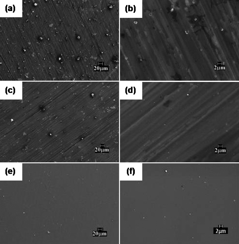
Images (FESEM) of as prepared sol–gel coatings: a, b dip coated, c–f spray coated and after surface pretreatment by c, d grinding and e, f grinding+silanisation (magnification a, c, e ×500; b, d, f higher magnifications of a, c and e)
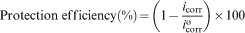
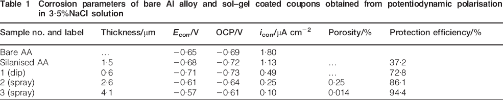
The potentiodynamic polarisation studies were carried out in 3·5%NaCl solution for the sol–gel coated coupons, and the plots are shown in Fig. 2a. The corrosion current density icorr values of the coated coupons were compared with that of the bare Al alloy substrate in order to determine the protection efficiency of the sol–gel coatings. The polarisation data are summarised in Table 1. For comparison, the corrosion parameters for bare Al alloy and silanised AA before spray coating are included in Table 1. It can be seen that silanisation alone does not provide any corrosion protection to the AA substrate. The OCPs of the spray coated samples were more positive than that of the bare alloy, showing ennoblement of the coated surface. The icorr values of the coated coupons were lower than that of the bare substrate, indicating improved corrosion resistance of the coatings. The spray coated coupons showed better corrosion resistance than the dip coated coupons probably due to the increase in coating thickness. The icorr value of coating 3 prepared by spray coating the sol on silanised substrate was lower than that of coating 2 prepared by spray coating the sol on ground substrate. The spray coated coupons also showed ∼50 mV positive shift in corrosion potential Ecorr than that of the bare substrate (−0·65 V), indicating the passive nature of the coating (Fig. 2a). The increase in corrosion current densities immediately after Ecorr indicated pit formation and onset of corrosion. The percentage of porosity and protection efficiency of the coatings were calculated from the polarisation data using the following equation20,
21
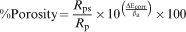
 are the corrosion current densities of the coatings and bare substrate respectively. The corrosion current density was obtained from intersection of the anodic and cathodic Tafel lines. The calculated porosities and protection efficiencies of the coatings are included in Table 1.
Polarisation plots of cerium doped sol–gel hybrid coatings (1, 2 and 3) with different surface pretreatments after a 1 h immersion and b 168 h immersion: polarisation plot of bare AA is also shown for comparison
Corrosion parameters of bare Al alloy and sol–gel coated coupons obtained from potentiodynamic polarisation in 3·5%NaCl solution
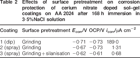
The potentiodynamic polarisation plots of the same set of sol–gel coated coupons after 168 h immersion in 3·5%NaCl solution are shown in Fig. 2b. The corrosion parameters are summarised in Table 2. It was found that the icorr of the dip coated coupon had increased considerably, indicating loss of corrosion protection for thin sol–gel coatings on prolonged immersion. The spray coated coupons, particularly coating 3, exhibited improvement in corrosion resistance with a low icorr of 0·68 μA cm−2 even after 168 h immersion.
Effects of surface pretreatment on corrosion protection of cerium nitrate doped sol–gel coatings on AA 2024 after 168 h immersion in 3·5%NaCl solution
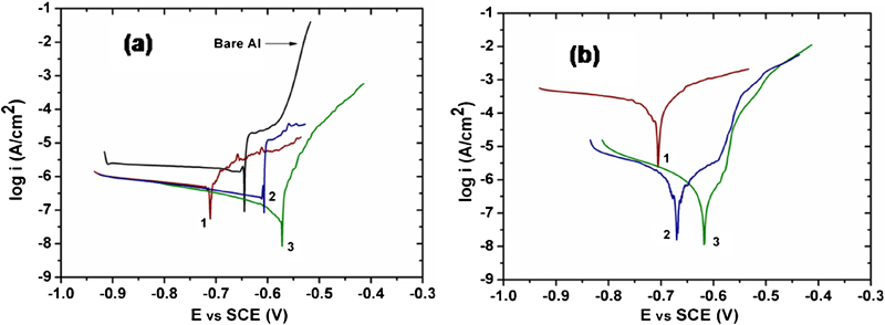
Impedance spectroscopic studies have been extensively used in a semiquantitative manner to measure and predict the protective performance of the sol–gel coated Al substrates to different times of exposure conditions.6,16 – 19,22,23 As the polarisation data obtained after 168 h immersion in 3·5%NaCl solution clearly showed that spray coated sol–gel coatings have better corrosion resistance than dip coated coating 1, coatings 2 and 3 were further evaluated by EIS. Figure 3 presents the impedance plots of coatings 2 and 3 after 1 and 168 h immersion in 3·5%NaCl solution. The appearance of two depressed semicircles in the Nyquist plot (Fig. 3a) for coatings (2a and 3a) with 1 h immersion indicates the two different capacitive behaviours of the coatings. This confirms the formation of two layers initially on the substrate surface in the sol–gel process: sol–gel layer (OL) and intermediate layer (IL) as reported earlier by Wang and Akid.6 Hence, the high and low frequency arcs are attributed to OL and IL respectively. The diameter of the low frequency semicircle had a higher slope value for coating 3 compared to coating 2 after 1 h immersion (shown in plots 2a and 3a). The Bode phase angle plot (Fig. 3b) also exhibited two peaks, one at the higher frequency range (103–105 Hz) and another at the intermediate range (10–103 Hz), which also further substantiated the two-layer behaviour of the sol–gel coating. The plateau appearing in the higher frequency range of the Bode magnitude plot for 1 h immersion could be assigned to the resistance provided by the outer porous layer (OL). After 168 h immersion, the corresponding plateau was not seen, and the two peaks in the phase angle plot became single. This is due to the saturation of the outer layer with the corrosive chloride ions and water molecules.
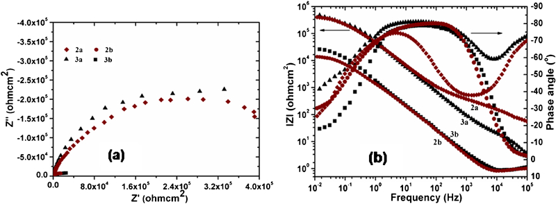
a Nyquist and b Bode plots of electrochemical impedance of cerium doped sol–gel hybrid coatings spray coated on AA 2024 with different surface pretreatments: coatings on ground (2a, 2b), on ground and silanised substrate (3a, 3b), after 1 h immersion (2a, 3a), after 168 h immersion in 3·5%NaCl solution (2b, 3b)
A well defined shallow peak approaching the phase angle closer to −40° was obtained for coating 2a compared to coating 3a. From the percentage of porosity of the coatings calculated using polarisation data (Table 1), it was expected that coating 2a with 0·21% porosity could have more penetration at the outer layer compared to coating 3a with 0·014% porosity. However, this has not been observed in the EIS analysis, and the reason could be due to the nature of the surface and the microporosity present on the outer layer of the coatings. It is possible that when the porosity is higher, the Ce ions could migrate from the intermediate layer to the outer surface, where the pores are present and precipitate as Ce hydroxide/oxides, thus providing improved corrosion resistance.16 Hence, the damage caused by the corrosive ion on the outer layer could be slightly less compared to coating 3a. The peak at the intermediate range for coating 3a was broad compared to the peak of coating 2a, indicating better inhibitive property of coating 3a. The value of the impedance modulus at low frequency (0·01 Hz) is a simple parameter used to compare the protection provided by different systems against corrosion.17 In the low frequency range (0·01–10 Hz), the coatings showed about two orders increase in impedance magnitude after 1 h immersion. However, after 168 h immersion, the impedance value decreased by about one order for both coatings; still, coating 3a showed a slightly higher impedance compared to 2a.
Figure 4 shows the equivalent circuits (ECs) obtained by fitting the impedance data to the coated coupons at 1 and 168 h immersion. The ECs contain the following elements:
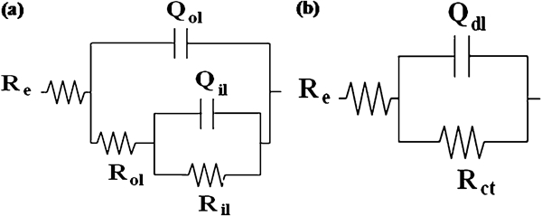
Equivalent circuits used for numerical fitting of impedance plots obtained for cerium doped sol–gel hybrid coatings (3a, 3b) after a 1 h and b 168 h immersion in 3·5%NaCl solution
solution resistance Re
sol–gel layer (outer layer) capacitance Qol, outer layer resistance Rol represents the resistance of the pore or defects in the sol–gel layer in parallel with Qol
intermediate layer capacitance Qil in parallel with intermediate layer resistance Ril, double layer capacitance Qdl and charge transfer resistance Rct.
The measured impedance is Re at the high frequency range and the sum of Re, Rol and Ril at the low frequency end. Constant phase element has been used in place of pure capacitor throughout the analysis to get satisfactory fit in all the systems. The exponent n represents the closeness of the constant phase element to the capacitor. The EC descriptions for coating 3 after 1 and 168 h immersion are Rs{Qol[Rol(Qil Ril)]} and Rs(Qdl Rct) respectively. The parameters of the sol–gel film/substrate systems obtained from fitting the experimental data with the ECs are given in Table 3. From the table, it is evident that the resistance provided by the outer layer Rol is ∼400 and 60 Ω cm2 for coatings 2a and 3a respectively. The very low resistance value obtained for the OL could be due to the existence of micropores in the coating through which the aggressive ion ingress and attacks the intermediate layer. The resistances provided by the compact intermediate layer for coatings 3a and 2a were ∼475 and 430 kΩ cm2. During immersion in NaCl solution, the electrolyte diffuses through the sol–gel layer at a rate determined by the pores/defects in the coating, eventually reaching the intermediate layer. At the initial immersion, the diffusion of the electrolyte is less, and the resistance provided by the intermediate layer was high.
Parameters of sol–gel film/substrate systems obtained from fitting of experimental spectra with different ECs
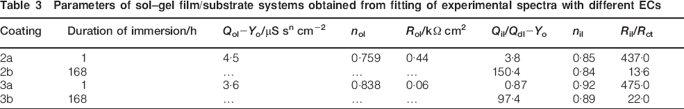
After 168 h immersion, the resistance to corrosive attack of coated coupons 3a and 2a decreased to ∼23 and 14 kΩ cm2, indicating that the electrolyte continued to interact with the coating and developed further conductive pathways even at the intermediate layer. The transformation from two time constant behaviours to a single one after 168 h immersion clearly indicated the onset of corrosion. There was an increase in the capacitance value and a corresponding decrease in the ‘n’ value (Table 3) observed after 168 h immersion in 3·5%NaCl solution, confirming the improved protection provided by coating 3 compared to coating 2. Therefore, it can be concluded that surface pretreatment by silanisation has helped to improve the corrosion protection of the AA 2024 alloy. Even after 168 h immersion, the cerium doped coatings exhibited improved corrosion resistance when compared to the bare substrate.
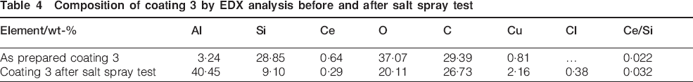
The coupons of coatings (1–3) were tested in a salt spray chamber. The dip coated coupon (coating 1) tarnished in 24 h and displayed pits. Coating 2 showed dark patches after 72 h; whereas, coating 3 remained bright and did not show any pits even after 168 h. Images (FESEM) of coating 3 after salt spray test are shown in Fig. 5. The coating surface showed the presence of white flakes after the salt spray test. The composition of coating 3 by EDX analysis before and after the salt spray test is given in Table 4. It was found that the Ce/Si weight ratio after the salt spray test was 0·032 on the coating surface. Thus, there was enrichment of cerium on the coating surface compared to that present in the as prepared coating, indicating migration of cerium to the damaged area.
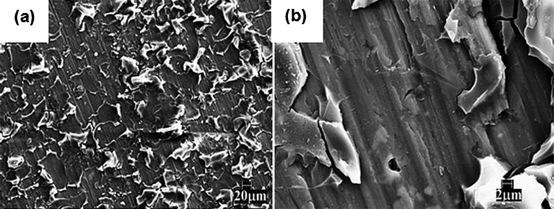
Images (FESEM) of sol–gel coating 3 after salt spray test for 168 h: a ×500; b ×5000
Composition of coating 3 by EDX analysis before and after salt spray test
Conclusion
Smooth crack free sol–gel hybrid films on AA 2024 were obtained through control of sol–gel process parameters like water/silane ratio and stirring time. The evaluation of corrosion resistance of the cerium doped sol–gel hybrid coatings by potentiodynamic polarisation measurements, EIS and salt spray test has shown that the coatings offered considerable corrosion protection to aerospace aluminium alloy AA 2024. Coatings applied by spraying had higher corrosion resistance than coatings applied by dipping due to increased thickness. The corrosion protection by the sol–gel coating was further enhanced by a simple surface pretreatment of the substrate by silanisation. This is very promising from the environmental standpoint because it avoids the use of strong acids and alkalis required for chemical surface pretreatment.
Footnotes
Acknowledgements
The authors are grateful to Dr A. R. Upadhya, Director, NAL, and Dr K. S. Rajam, Head, Surface Engineering Division, NAL, for their constant support and encouragement of this work. They thank Mr Siju, SED, NAL, for the technical assistance with FESEM of the coated samples. They acknowledge the financial assistance received from CSIR Supra Project under the 11th Five Year Plan scheme for carrying out this work.