
Abstract
Nanostructured alumina coatings have been deposited on SS 304 substrate using atmospheric plasma spray process. In the present work, nanostructured feed powder is obtained by manual granulation of nano-Al2O3 powder particles followed by exhaustive sieving, which is helpful in their proper consolidation. The tribological performance of the nano-alumina coatings, such as dry sliding, slurry erosion and cavitation erosion, has been investigated and compared with conventional coatings. The superior wear and erosion resistance of nanostructured coatings as compared to conventional coatings are due to its higher hardness and effective hindrance to crack propagation. Wear mechanism was explained based on their microstructure and worn surface morphologies. The microhardness and porosity of the two coatings were also experimentally investigated.
Introduction
Mechanical components operate under severe conditions, such as high load, speed, temperature and hostile chemical environment, in a wide variety of applications, such as exhaust manifold/headers, pump shafts, wear sleeves, crankshaft bearings, etc. Surface modification techniques like protective coatings are quite useful in protecting these components against various types of degradation.1 Ceramic coatings produced by thermal spray techniques are widely used for a range of industrial applications to provide wear resistance, erosion resistance, corrosion protection and thermal insulation. Alumina coatings, as well as bulk alumina tiles, are commonly used to resist the wear caused by solid particle erosion and friction.2 The wear resistance of hydraulic components enhanced by using coatings can be applied by arc welding, thermal spraying and chemical or physical vapour deposition, among other techniques, as reported in the handbook of thermal spray technology.3 The main disadvantage of the application of welding overlays is the high heat input into the material, which leads to microstructural changes and usually demands post-weld heat treatment. Thermal spray processes, on the other hand, enable the fabrication of coatings with minor modification to the substrate properties due to the low heat input of the process. In addition, the application of the coatings is usually easy and fast, a wide variety of materials can be deposited and minimal surface preparation is needed.4 Plasma spraying is the most flexible or versatile thermal spray technique, and oxide ceramic coatings, such as alumina and chromia deposited by this technique, exhibit very high hardness, excellent wear resistance and high temperature stability, which are essential for tribological and high temperature erosion applications.5, 6 In recent times, nanostructured ceramic coatings are preferred due to their superior mechanical properties compared to conventional coatings (CCs). It is due to the effective hindrance to dislocation movements, which leads to the enhancement of strength and hardness.7 Further, several investigators have shown that the nanostructured coatings (NCs) exhibit a bimodal microstructure, which imparts improved toughness to coatings, resulting in better tribological properties as compared to their conventional counterparts.8 – 10 Plasma spraying of nanoparticles is a difficult task due to the lack of momentum of these powder particles. The spray drying process is used as an effective nanopowder granulation technique for obtaining flowable agglomerated powders. This process is commonly used for the development of ceramic coatings from nanopowders, as reported in the literature, but it is an expensive route.11 – 14
The tribological behaviour of nanostructured Al2O3 coating is limited in the literature. In the present work, tribological properties such as slurry erosion, cavitation erosion and sliding wear of the conventional and nanostructured Al2O3 coatings deposited by atmospheric plasma spray process on stainless steel (SS) 304 substrate are investigated. An attempt has been made for the first time to prepare flowable nanostructured Al2O3 by manual granulation and exhaustive sieving of the starting nano-Al2O3 powder instead of using spray drying, which is a complex and expensive process.
Materials and methods
Preparation of feed material for plasma spray
Two different particle sizes of Al2O3 powder were used for the plasma spray deposition of coatings on SS 304 steel substrates (Table 1). The average particle size of the Al2O3 powder used for plasma sprayed CC was 40 μm (99·9%; SD Fine Chemicals Ltd, India), and that for plasma sprayed NC was 80 nm (99·99%; Zibo Xinfumeng Chemicals Co. Ltd, China). Manual granulation of the nanosized alumina powder has been carried out by using 3 wt-% organic binder, polyvinyl alcohol (polyvinyl alcohol LR; S.D. Fine Chemicals Ltd, Mumbai, India). The molecular weight of the polyvinyl alcohol binder used was 14 000. Manual granulation of the nanopowders has resulted in a wide range of powder sizes, which were consolidated to the required micrometre size by ball milling followed by thorough sieving using a sieve shaker. The granulated nanopowder was dried in a furnace for 3 h before spraying after sieving.
Elemental analysis of SS 304 substrate
A 3MB Sulzer Metco gun employing atmospheric plasma spray technique was used to deposit CC and NC on grit blasted SS 304 substrate using a 40 kW Miller thermal plasma spray equipment in the present work. Silica particles were used in grit blasting the substrate surface to remove its contaminants and grease. A Ni–Cr based bond coat (43VF-NS, Sulzer Metco, Wholen, Switzerland) was applied to the substrate surface to provide better adhesion characteristics of the substrate before the alumina coating was deposited. The spray process parameters used for both nano- and conventional alumina coatings are given in Table 2.
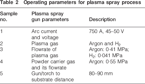
Operating parameters for plasma spray process
The stainless steel substrate used for the deposition of coatings was prepared in the form of blocks and pins. Square blocks with a dimension of 20×15×5 mm were used for microstructural characterisation, slurry erosion and cavitation erosion testing. Cylindrical pins of 8 mm diameter and 30 mm height were used for sliding wear investigation of the coated samples against the counter surface of the Al2O3 coated discs.
Coating characterisations
The nano- and micrometre sized alumina powders and their coatings were characterised by X-ray diffraction analysis (Bruker AXS, D8 ADVANCE) using Cu Kα radiation (1·5410 Å) at a moderate scanning speed of 1° min−1 between 2θ = 20 and 80°. A field emission scanning electron microscope (FE-SEM, FEI Quanta 200F) was used to investigate the microstructural characteristics of the coatings. For cross-sectional imaging, the samples were cut using a diamond cutter at lower speed (60 rev min−1) and then mounted on a plastic base. Energy dispersive spectroscopy was used for the elemental analysis of the coatings. Scanning electron microscopic (Leo 435VP) images of the coated samples and the powders were also captured. The particle size of the nano-alumina powder was also measured from the FE-SEM images using Image-J software. Porosity measurement of the coatings was carried out using image analysis technique by taking the average of 20 pore sizes on each sample. Vickers microhardness tester (Leitz, Wetzlar, Germany) was used to determine the hardness of the coatings under a load of 200 gm (1·961 N) applied for a dwell time of 30 s.
Tribological testing
Dry friction and sliding wear test were performed on the coated specimens (ø8×30 mm long pin) using a pin on disc type wear testing machine (Magnum Engineers, Bangalore, India) as per the ASTM wear testing standard G99-04.15 The steel discs used for dry sliding testing were plasma coated using Al2O3 powder (average particle size: ∼50 μm). The plasma sprayed CC and NC samples used for the pin on disc experiment have coatings on one of the flat ends of the cylindrical pins, which are pressed against the coated discs. All the tests were carried out at room temperature with a relative humidity maintained at ∼45%. A constant sliding velocity of 1·0 m s−1 was used for the wear test. The wear tests were performed for the maximum duration of 30 min, covering 1800 m of sliding distance at this constant velocity. The end loads of 5, 10 and 15 N were used to evaluate the tribological properties of the coatings. The Al2O3 coated disc and the coated pins were polished to a surface roughness of ∼0·5 μm using different grades of abrasive paper and finally cloth polished using fine alumina powder. The specimens were thoroughly cleaned with acetone in an ultrasonic cleaner before and after the wear test followed by drying using hot air dryer. After every 10 min of test run, the weight of the samples was measured, and the wear debris was removed to avoid their presence in between the contacting surfaces. Weight loss of the coated samples during the wear test was measured using an electronic balance with a resolution of ±0·1 mg. The wear rate of the coatings was estimated from the weight loss divided by the sliding distance.
Slurry erosion test on the coatings was performed using a slurry pot with three different concentrations of silica. A solution of 10% (C10), 20% (C20) and 30% (C30) silica particles, in water, with particle size ranges of between 106 and 150 μm, was used as three different slurry concentrations. Test samples of CC and NC of alumina were placed in the holder, which was rotated at 800 rev min−1 such that the coating surface comes in contact with erosive slurry. The samples were ultrasonically cleaned, dried and weighed before and after every 2 h of test run. The test was performed for 10 h, and three similar sized samples of each were taken at a time for the same concentration. The wear performance was evaluated in terms of weight loss observed during the test.
The cavitation erosion test was carried out using an ultrasonic vibratory tester. The ultrasonic vibratory tester comprises of an electronic generator that generates 250 W of average electrical energy. The transformer/velocity horn amplifies the small vibrations. This system uses a device to vibrate the probe immersed in distilled water. This standard test procedure was performed according to ASTM G32-06.16 The test specimen was placed at a small distance of between 0·5 and 1·0 mm below the tip of the ultrasonic probe, as shown in Fig. 1. The cavitation erosion test was conducted for a total duration of 12 h, and weight loss was measured after every hour of testing. The samples were cleaned in acetone, dried and weighed to an accuracy of 0·1 mg using an electronic balance. The eroded surface was characterised using an optical microscope and an FE-SEM to identify the erosion mechanisms.
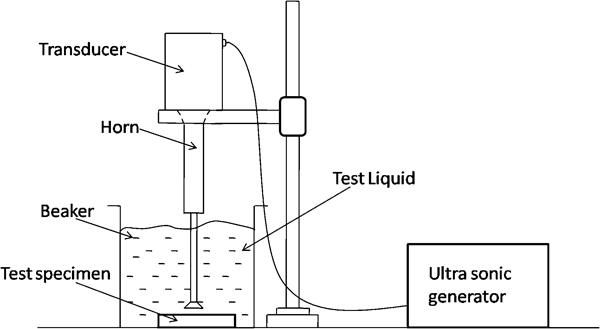
Ultrasonic vibrating tester used for evaluating cavitation erosion
Results and discussion
Microstructural characteristics and hardness
Figure 2a and b shows the granulated nanostructured Al2O3 powder composed of nanograins. The nanostructured Al2O3 powder particles with nearly spherical morphology are observed in Fig. 2b. The transmission electron microscope (TEM) image, as shown in Fig. 2c also, confirms the nanostructure of the starting powder as stated.
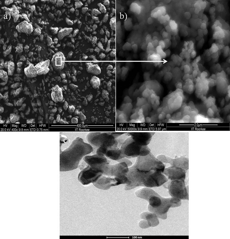
Images (FE-SEM) of granulated nanostructured Al2O3 powder at a ×400 and b ×50 000, and c TEM image of granulated powder
The plasma sprayed coatings exhibit a lamellar morphology with splats of different sizes (Fig. 3). The splat size of CCs is larger as compared to NCs. The NC exhibits a duplex structure consisting of both fully melted splat lamellae and unmelted regions within splats. This could be mainly attributed to two reasons: (1) the use of agglomerated nanopowder for NCs as compared to fused and crushed solid powder particles for CCs; and (2) the fact that the residence time of Al2O3 coating powders inside the plasma jet is less. There is little time for the agglomerated powders to completely melt as compared to conventional powders.17, 18 Further, the process parameters used in the plasma spray gun ensure the formation of a nanograin morphology due to the impact of partially molten agglomerated nanopowders on the substrate in the present work. It has also been confirmed by reported studies on nanoceramic coatings using similar process parameters.10, 11, 19 The nanostructured powders exhibit a low thermal conductivity in comparison to conventional powders, and their melting behaviour may be different, depending on their size and trajectory in the plasma jet. Further, it is quite pertinent that the nanostructured powders which are used in reconstituted granular form enter into various zones of the plasma plume during spraying. Powders which remain only in the outer portion of the plasma plume suffer melting, but the inner portion remains unmelted, resulting in a bimodal structure, whereas the powders passing through the central region of the plume melt fully, resulting in a structure akin to that of the CC.20 The properties of coatings strongly depend upon the morphology of the splats deposited on the substrate by plasma spraying of feed powder particles. It has been observed that the splats obtained on the as bond coated SS 304 substrate surface do not show splashing (Fig. 3), which indicates good adhesion of the coating.21
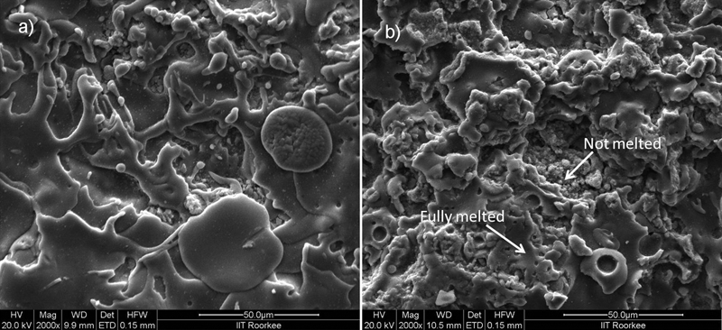
Images (FE-SEM) depicting microstructural difference between a CC and b NC
In this work, nanopowder granulation was carried out manually, which resulted in agglomerated particles of irregular size and shapes, in contrary to spherical and almost similar sized particles obtained after spray drying. Therefore, the fully melted and unmelted regions of varying sizes on the NCs are observed. The coating thickness varied between 181 and 241 and 117 and 155 μm for NC and CC respectively, as measured by ImageJ software. The two coatings show an appreciable amount of interlamellar pores having a size range of 1·37–14·05 and 0·85–12·58 μm for NC and CC respectively. The NC exhibits more porosity than the CC, contrary to the reported values in the literature.22 The Vickers hardness (HV) of the coated test samples is measured across the cross-section. The maximum microhardness measured for CC and NC are 940±72 and 1160±122 HV respectively. The microhardness of the NC coating is higher than the CC and has more fluctuation along the cross-section. The maximum microhardness value of the coated disc surface is 845±46 HV, which is quite less as compared to the hardness value of the coating obtained on the test specimens.
The NCs which contain unmelted powder can exhibit higher hardness due to the presence of retained α-phase, which is the most stable and harder phase.23 The X-ray diffraction pattern shown in Fig. 4 of the as sprayed nanostructured alumina coating (NC) on the SS 304 substrate clearly shows the presence of a strong peak corresponding to the α-Al2O3 phase (rhombohedral crystal structure with R-3c space group) than that of the micrometre sized alumina coating (CC). Further, the peak broadening of NC compared to CC, as evident from Fig. 4, suggests the existence of a nanostructured microstructure.
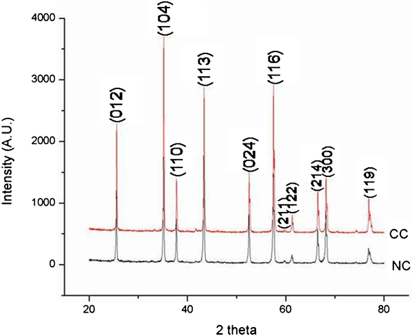
X-ray diffraction patterns of nano- and conventional Al2O3 coating on SS 304 substrate
Tribological properties
Sliding wear
The sliding wear performance of CC and NC pins against Al2O3 powder coated steel disc has been evaluated for three loads (5, 10 and 15 N) under the dry condition of contact surfaces. The wear performance of the two coatings was measured in terms of relative weight loss. It has been observed that for the end loads of 5, 10 and 15 N, both coatings exhibit a progressive weight loss for a total sliding distance of 1800 m (Fig. 5). As the sliding progresses, there is a gradual increase in the difference between the weight loss of the NC and CC coated samples for the same sliding distance. This difference is more prominent in CC than for NC after 600 m of sliding. It can also be inferred from Fig. 5 that the weight loss under 10 and 15 N loadings used for CC is quite large as compared to others. The weight losses under 10 N loading for NC and 5 N loading for CC demonstrate only a small difference. The wear resistance exhibited by NC is almost 1·84 times than that of CC. This significant increase in wear resistance of NC as compared to CC is mainly attributed to its bimodal structure and high hardness since the major wear phenomenon observed is abrasive. The FE-SEM images of the worn surface, as shown in Fig. 6, and the large amount of debris collected clearly indicate the occurrence of three-body abrasion between the two sliding surfaces. Wear debris may be produced by the fracture of brittle surface under repetitive contact forces or by chipping, as reported earlier also.24 Hard Al2O3 particles, which get detached from the coated surface during sliding, act as an abrasive between the two sliding surfaces and result in material removal. Initially, wear takes place by the adhesion mechanism between the hard asperities of the two surfaces in contact, but as the test proceeds, the abrasion wear mechanism is observed to be dominant. Similar observations were also made earlier by various researchers.25, 26 Further, the worn surface morphologies of the alumina coatings indicate the obvious difference between the coatings sprayed with conventional and nanosized powders and their wear behaviour, as shown in Fig. 6. The worn surface of the NC appears to be smoother without many grooves despite the microcrack and plastic deformation (Fig. 6a). The worn track on the CC is rough (Fig. 6b), and grooves and microfracture features are also observed on the worn surface.
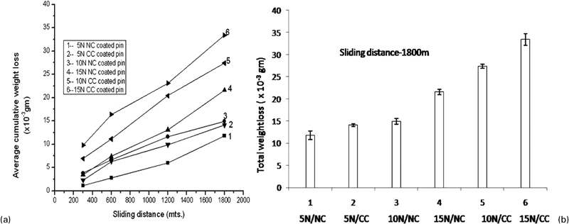
Comparisons of weight loss observed between NC and CC samples subjected to dry sliding at three loads, i.e. 5, 10 and 15 N: a without error distribution; b with error distribution
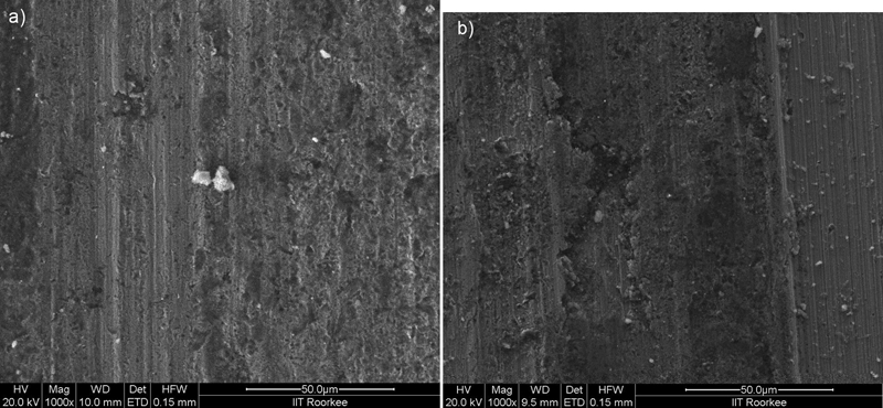
Images (FE-SEM) of worn surfaces: a nano-alumina; b conventional alumina
By considering the variation of coefficient of friction for the two coatings with respect to sliding time, it is observed that CC exhibits a higher value of frictional coefficient (0·65–0·8) than NC (0·6–0·7) at all the loads. Figure 7 show the variation of the average coefficient of friction with sliding time at 15 N end load taken for the experiment. The friction coefficients initially show smaller values, as all the asperities are not in contact with the sliding surface due to the surface roughness of the as coated specimens. After a number of revolutions, due to the cutting of higher asperities, the friction coefficient tends to become constant. If initially these asperity peaks are more in contact, a higher value of friction coefficient may be noticed, as reported in the literature.27
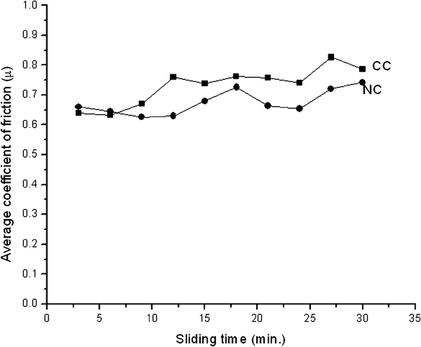
Comparison of sliding coefficients of friction of NC and CC samples
Slurry erosion testing
Slurry erosion test was carried out for three different concentrations (C10, C20 and C30) using the three similar sized samples of each coating. Erosive particles strike the coated surface rotating in the slurry at 800 rev min−1. The two coatings exhibit loss of weight, which is considered as measure of the erosive wear. For both coatings (NC and CC), the samples tested for 8 h exhibit a continuous loss of weight at all the slurry concentrations. The difference in the weight losses of NC and CC becomes quite significant in C30 concentration as compared to C10 and C20, as shown in Fig. 8. The loss of weight for both coatings at C10 and C20 concentrations exhibits little differences, and their graphs have similar slopes. It is also observed that the erosion is increasing with increasing abrasive particle concentration. The erosion of the coating occurs mainly via microcutting, microploughing under the impact of abrasives (Fig. 9) as well as delamination of lamellas. It is well known that the plasma sprayed coating exhibits a lamellar structure, and these interfaces can be seen as precracks in the coating. These cracks tend to propagate along the bonded fraction of the lamellar interface when the abrasive strikes repeatedly with high velocity. This results in the spalling of the lamella, resulting in material loss.28, 29 In the NC, the improvement in slurry erosion performance as compared to their conventional counterparts (CC) may be due to its enhanced toughness, which is caused by microscopic crack blunting and deflection, as observed in Fig. 10 and also reported in our earlier work.30 In Fig. 10b, we can clearly observe several crack arresting sites at the unmelted/partially melted regions observed only in NC samples subjected to slurry erosion testing. Unlike CCs, where the increase in hardness is often accompanied by a decrease in toughness, these NCs seem to defy this trend by possessing an increase in both properties.
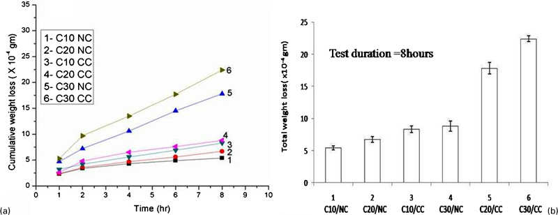
Comparative slurry erosion performances of NC and CC observed at C10, C20 and C30 concentrations a without and b with error distribution
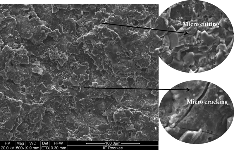
Image (FE-SEM) showing mode of failures observed during slurry erosion of CC sample at C30 concentration
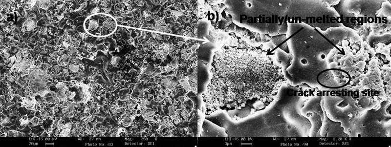
Images (SEM) showing eroded surface of NC sample at a low and b higher magnifications with visible crack arresting sites
Cavitation erosion testing
The weight loss difference between CC and NC for 3 h of testing is negligible, and it increases gradually as the testing progresses. The NC exhibits better cavitation erosion resistance as compared to CC, which can be clearly observed in Fig. 11. The major erosion phenomenon observed is brittle fracture and microcracking of laminates, as observed in the literature.31 The FE-SEM images in Fig. 12 show large pits, indicating loss of material during cavitation erosion for CC. A closer observation of the same indicates the occurrence of cracking of laminates during cavitation erosion as large numbers of laminates with sharp edges are seen. A similar phenomenon is observed for NC (Fig. 13). It is evident that the NC surface shows smaller sized pits as compared to CC, and the phenomenon of erosion is by brittle fracture of laminates and detachment of partially melted particles. On closer investigation, it is also observed that the toughening phenomenon by means of crack blunting is taking place in the NC during cavitation erosion testing. The NC has shown better resistance as compared to CC due to its high hardness and resistance offered to crack propagation.
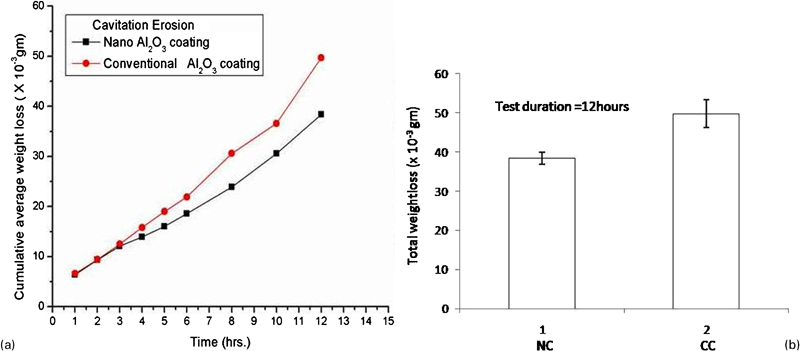
Comparative cavitation erosion performances of NC and CC: a without error distribution; b with error distribution
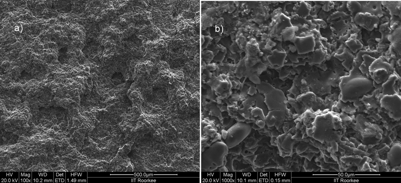
Images (FE-SEM) of surface of CC after cavitation erosion a showing large pits and b closer observation showing sharp edges of laminates
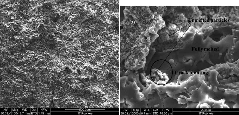
Images (FE-SEM) of surface of NC after cavitation erosion a showing small pits (pores) and b closer observation showing crack blunting at unmelted regions of coating structure
Conclusion
Sliding wear, erosive wear and cavitation erosion behaviours of plasma sprayed Al2O3 coatings (NC and CC) on SS 304 substrates were investigated, and the following conclusions are made.
Both coatings exhibit a lamellar structure and a fair amount of porosities.
The sliding wear rate of the nanostructured Al2O3 coatings measured against Al2O3 coated plates was lower than that of the CCs under all the experimental conditions. The weight loss under 10 and 15 N loadings used for CC is quite large as compared to others. A similar weight loss is observed for the 10 N loading for NC and the 5 N loading for CC. The investigation of worn surface and the large amount of wear debris collected clearly indicated the abrasion as the major wear phenomenon for both CC and NC samples.
The NCs exhibit a lower friction coefficient and a better wear resistance than the CCs.
Slurry erosion test was carried out for three concentrations, i.e. C10, C20 and C30. The erosion of the coating occurs mainly via microcutting, microploughing under the impact of abrasives and delamination of lamellas.
Cavitation erosion was also studied for both coatings. The NC and CC exhibited quite similar modes of surface deterioration under this method of erosion. However, due to the crack blunting phenomenon observed for NC and its high hardness, its erosion resistance is higher than that of the CC.