
Abstract
Ni–P composite coatings containing SiC nanoparticles or carbon nanotubes (CNTs) were deposited on steel substrates via electroless plating technique. An electrochemical polarisation technique was employed to measure the porosity of Ni–P and composite coatings in as plated condition. The technique was based on the changes observed in the corrosion potential with varying cathode and/or anode area on a bimetallic corroding system. Electrochemical impedance spectroscopy (EIS) test was used to assess the corrosion resistance of the coatings. Results showed that incorporation of nanoscaled second phases could decrease the area fraction of porosity from 2··5×10⁻⁵ for Ni–P coating to 2×10⁻⁷ for Ni–P–CNT coating. Ni–P–CNT coating exhibited the least porosity that it could be attributed to the morphology of CNTs and their ability to fill out the pores more effectively as compared to SiC nanoparticles. EIS results were in agreement with the porosity results as Ni–P–CNT coatings illustrated the highest corrosion resistance.
Introduction
The ability to codeposit second phase within Ni–P electroless deposited coatings has led to generation of recently developed Ni–P composite coatings.1 – 4 Successful codeposition and properties of electroless composite coatings are dependent on various factors including particles size,5, 6 their concentration in the bath7 and particle nature.3 The primary objectives of composite electroless coatings have been to improve the wear resistance and/or corrosion resistance and/or lubricity of machinery parts.4, 8 Among different second phases codeposited with Ni–P, carbon nanotubes (CNTs) and SiC particles have the highest potential.8 Owing to their high wear resistance and the low cost of ceramic powder, metal matrix composite coatings containing SiC have been investigated for the protection of friction parts.9 – 13 CNTs have exceptional mechanical, electrical and thermal properties, together with a high geometrical aspect ratio (ratio between length and diameter). Some studies showed that Ni–P–CNT composite coatings exhibited higher wear resistance and lower friction coefficient in comparison with traditional electroless composite coatings such as Ni–P–SiC and Ni–P–graphite.14 – 18 In general, the electroless Ni–P composite coatings is thought to have less corrosion resistance than that of electroless Ni–P alloy coatings.3, 19 The deposition of second phase particles present in the electroless nickel matrix is believed to reduce passivity and corrosion resistance of the coating. Hence, for applications requiring good corrosion resistance, a duplex coating, consisting of an initial electroless Ni–P coating followed by an electroless Ni–P composite coating, is recommended in place of electroless Ni–P composite coatings.3, 19, 20 The good anticorrosion performance of electroless Ni–P coatings has been attributable to the relatively low porosity of deposit and its phosphorous content. Choudhury et al.21 showed that reducing agent significantly affects the phosphorous content of the Ni–P coatings. In fact, corrosion resistance of electroless Ni–P coatings depends on many factors such as bath composition, post-heat treatment22 and the corrosive medium.4 Nickel coatings are non-sacrificial to many common engineering metals/alloys. For example, they are cathodic to carbon steels. Therefore, the presence of any discontinuities or pores in the coating may result in accelerated localised attack (pitting of the base metal, or undercutting of the coating) because of the high cathodic to anodic surface area ratio. The porosity of electroless Ni–P deposits can be affected by pretreatment processes, surface roughness, bath composition and other constraints.4,23 – 25 The formation of nodular deposits, as a result of pretreatment process,26 inclusions in the deposit or defects in the substrate surface, and debris in the bath, also may be attributable to the presence of pores in the coating.23 Other investigators have reported that the trapping of hydrogen bubbles during nickel deposition can cause pores in the coating.24 – 27 Some studies showed that the incorporation a second phase in Ni-P coatings can reduce the porosity of the coatings. Yang et al.28 reported that the dispersion of CNTs in order to fill out the microholes and defects of Ni–P coatings can specially influence the corrosion resistance of Ni–P–CNT coatings. Rabizadeh and Allahkaram29 studied the corrosion resistance of Ni–P–SiO2 composite coatings and showed that the high values of charge transfer resistance of Ni–P–SiO2 composite coatings as compared to Ni–P coatings implies the less porosity of the former. Ferroxyl test, salt fog exposures and the electrographic tests are typically used to determine coating porosity. These tests are widely used to evaluate the quality of electroless Ni–P coatings, and the test procedures are described in ASTM B733 and ASTM B117.30, 31 In order to develop a reliable porosity test, some investigators have tried to extend the electrochemical technique for faster and more accurate measurement of porosity.25, 27, 32, 33 Chen et al.34 have measured the porosity of TiN coating via different electrochemical methods consisting anodic current measurement, colorimetric method and measurement from corrosion potential and polarisation resistance and showed that these techniques revealed a similar result for porosity measurements of the coating. Lins et al.33 used electrochemical impedance spectroscopy (EIS) and linear polarisation methods to evaluate the porosity of phosphate coatings and showed that the porosity values measured using the two techniques were in good agreement to each other. Singh25 employed an electrochemical polarisation technique based on the changes taking place in the electrochemical parameters with varying cathode to anode area ratio on a bimetallic corroding surface to determine the porosity of electroless Ni–P coating. His studies showed that the electrochemical parameters could be used to obtain a qualitative indication of the area of the exposed pores. Studies have been made, so far, on the porosity of different coatings using different techniques, but have rarely been used to study the porosity of electroless Ni–P composite coatings. The current study presents a simple correlation of coating porosity versus parameters obtained from electrochemical technique based on the changes observed in the electrochemical parameters with varying cathode to anode area ratios on a bimetallic corroding system. The approach was used to evaluate variations in the porosity of electroless Ni–P coatings associated with incorporation of SiC and CNT nanoparticles in the coatings. The corrosion resistance of the coatings was also assessed via EIS method in 3··5% NaCl solution in order to confirm the polarisation measurement results.
Material and methods
Pristine chemical vapour deposition grown multiwalled carbon nanotubes (purity ⩾98%, diameter: 40–60 nm, length range: 5–15 μm) were used as composite constituents in this study. In order to improve the dispersion of CNTs in electroless bath, the as received CNTs were ball milled for 8 h with a planetary ball mill machine in an electroless solution at a rotating speed of 500 rev min−1. Ball to powder ratio was kept constant at 50∶1. β-SiC nanoparticles with an average size of 40 nm were also used as another composite constituents with Ni–P coating. Figure 1 shows the SEM images of β-SiC nanoparticles and ball milled CNTs. Sodium dodecyl sulphate was utilised as the surfactant additive in plating bath solution. This is used mainly for dispersion of the nanosize particles/tubes in the bath and consequently in the coating.35
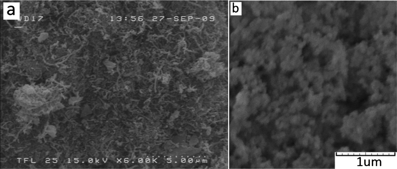
SEM images of a ball milled CNTs and b β-SiC nanoparticles
Ni–P, Ni–P–-CNT and Ni–P–SiC composite coatings were deposited on API-5L X65 steel substrates (30×25×15 mm), while the sample was vertically positioned in a 250 mL bath. The procedure for the preparation of the substrate has already been described in a previous paper.29 An electroless nickel–phosphorus bath with sodium hypophosphite as reducing agent was used to obtain coatings containing 8–10 wt-% of phosphorous. Deposition of composite coatings were performed in two steps; an interlayer of Ni–P coating with a thickness of 9±2 μm was initially deposited on the substrate by immersing substrate in the 200 mL electroless nickel bath followed by an electroless composite second layer. Bath was agitated using a magnetic stirrer with 300 rev min−1 during plating process. To obtain Ni–P–CNT and Ni–P–SiC composite coatings, 25 mg L−1 CNT and 1 g L−1 SiC nanoparticles were added to 50 mL electroless baths separately and 2 g L−1 of sodium dodecyl sulphate was added to each bath. Before plating commencement, the baths agitated by an ultrasonic probe (28 KHz frequency and 400 Watt power) with magnetic stirring for 1 h. After deposition of Ni–P interlayer, SiC or CNT contained bath was added to the main bath and coating continued for another 2 h in the presence of CNT or SiC nanoparticles. Magnetic stirring was continued during the coatings deposition. Bath condition for deposition of composite coatings was the same as depositing interlayer. For comparison purposes, pure Ni–P coating was also prepared under the same conditions. For porosity measurements, three sheets of pure nickel (10×7 cm) used as substrates, were also prepared and plated with Ni–P, Ni–P–CNT and Ni–P–CNT coatings respectively.
The surface morphologies and elemental composition of the coatings were characterised by SEM (CAMSCAN MV2300) equipped with an X-ray energy dispersive spectrometer. The electrochemical porosity test that was used in current study was based on the principle that describes the effect of cathode to anode area ratio on the corrosion potential. The corrosion potential Ecorr of a bimetallic couple, where the anodic area is much smaller than the cathodic area is given by equation (1)36
Results and discussion
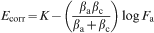
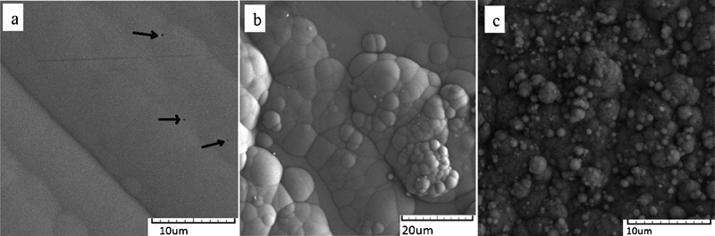
SEM images of the surface morphologies and cross-sections of the coatings have been shown in Figs. 2 and 3. Black arrows in Fig. 2a show some pores in the Ni–P coating. It is evident that the incorporation of a second phase can increase the nodularity of electroless Ni–P coatings and hence, it can decrease the corrosion resistance of the coatings because nodule boundaries or grooves boundaries, dislocations, kink sites and other surface defects are prone to corrosion attacks, so they can influence corrosion resistance of the electroless Ni–P coating.23 Figure 3 shows that all the coatings have the same thickness of 26±2 μm.
SEM images of surface morphology of a Ni–P (dark arrows show pores), b Ni–P–CNT and c Ni–P–SiC composite coatings
SEM images of cross-section of a Ni–P, b Ni–P–CNT and c Ni–P–SiC composite coatings
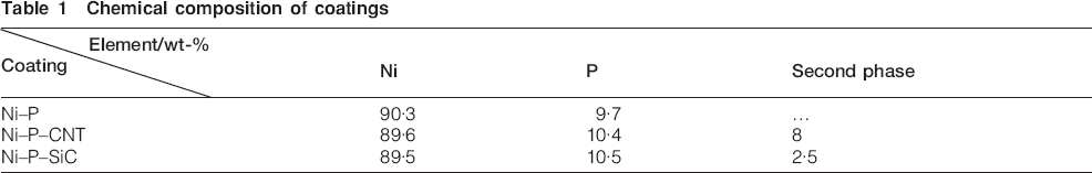
The composition of the coatings evaluated via energy dispersive spectrometer is given in Table 1. It is evident that the incorporation of a second phase does not have a significant effect on the phosphorous content of the coatings. It is a well known fact that the microstructure of electroless Ni–P films varies with the phosphorous content in the film37, 38 and according to the results, no change in the structure of the coatings is expected.
Chemical composition of coatings
The changes in corrosion potential versus area fractions for bimetallic systems were plotted in Fig. 4. This was used as a standard reference plot for evaluating the porosity of Ni–P and Ni–P composite coatings. The Ecorr values obtained for uncoated and Ni–P coated steel was −512 and −256 mV respectively. Therefore, the redox potential of the couple made of these two pieces of metals should change between −512 to −256 mV, as was the case in the present study. It was observed for values of the anodic area fraction from 0··35×10−3 to 89×10−3, the corrosion potential varied from −361 to −476 mV. The Ecorr values of Ni–P, Ni–P–CNT and Ni–P–SiC coatings are tabulated in Table 2. It can be observed that the corrosion potential became less negative in the case of composite coatings. The least electronegative Ecorr was observed in the case of Ni–P–CNT composite coating. The pore area fraction, in the coatings, could be read off from the calibration plot (Fig. 4) for the corrosion potentials observed. These results are given in Table 2. The values of Ecorr, and the corresponding pore area fractions, clearly show that the porosity of the coating decreased as a second phase was incorporated in the electroless Ni–P coating. This can be attributed to the filling out ability of the porosity by second phases, during the deposition. Table 2 shows that Ni–P–CNT composite coatings have the least corrosion potential and the least pore area fraction. This behaviour can be attributed to the smaller size, morphology, high geometrical aspect ratio and higher content of CNTs compared to SiC nanoparticles, so they can fill out the pores of the Ni–P deposition more effectively and provide the best pore free coatings.
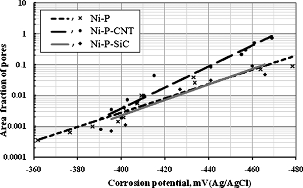
Calibration plot for pore area fraction and corrosion potential for electroless Ni–P, Ni–P–CNT and Ni–P–SiC composite coatings
Corrosion potentials and relevant area pore fractions of the coatings
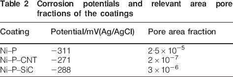
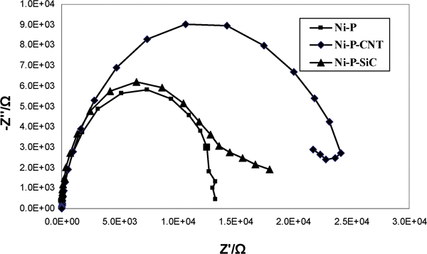
Figure 5 shows the Nyquist plots obtained for Ni–P, Ni–P–CNT and Ni–P–SiC composite coatings in 3··5% sodium chloride solution at their respective OCPs. All curves appear to be similar (Nyquist plots), consisting of a single semicircle at the high frequency regions signifying the charge controlled reaction. However, it should be noted that though these curves appear to be similar with respect to their shape, they differ considerably in their sizes. This indicates that the same fundamental processes must be occurring on all these coatings but over a different effective area in each case.3,
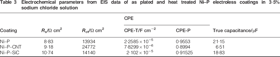
38 To account for corrosion behaviour of the coatings, an equivalent electrical circuit model given in Fig. 6 has been utilised to simulate the metal/solution interface and to analyse the Nyquist plot. The charge transfer resistance Rct and constant phase element values of the coatings have been compiled in Table 3. The values of the charge transfer resistance Rct obtained for the coatings of present study imply the best corrosion protective ability of Ni–P–CNT coating. The true capacitance of the coatings was measured from constant phase element (CPE) values of the coatings using equation (2)39

Electrochemical impedance diagrams of Ni–P, Ni–P–CNT and Ni–P–SiC composite coatings in 3··5 wt-% NaCl solution
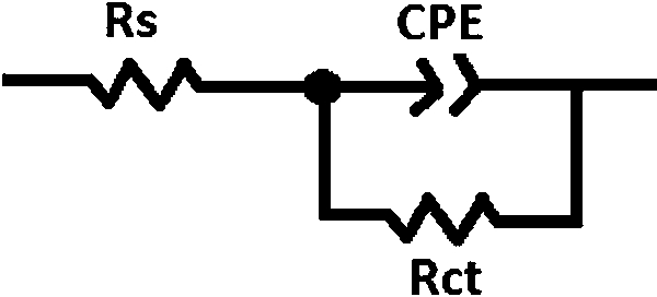
Equivalent electrical circuit model for corrosion behaviour of Ni–P, Ni–P–CNT and Ni–P–SiC composite coatings in 3··5 wt-% NaCl solution
Electrochemical parameters from EIS data of as plated and heat treated Ni–P electroless coatings in 3··5% sodium chloride solution
Conclusion
The incorporation of SiC or CNT nanoparticles could decrease the porosity level of Ni–P coatings from 2··5×10⁻⁵ to 3×10⁻⁶ and 2×10⁻⁷ respectively, which can be attributed to the filling out effect of the particles during deposition process.
Because of their morphologies, higher aspect ratio and higher content, CNT particles have more ability to fill out the porosity of the coatings and provide better pore free coatings as compared to SiC particles.
EIS test results in 3··5% sodium chloride confirmed that the Ni–P–CNT coating has the best corrosion resistance due to the more effective filling out ability of CNT as compared to SiC nanoparticles.