
Abstract
Ta was added to laser clad NiCrBSi coating to improve wear resistance. In situ synthesised TaC particles of nearly equiaxed shape were uniformly dispersed in the coating. The colony that contained acicular Cr rich boride or carbide grew radially around the TaC particle and had a strong bond with the particle. The TaC particles had good bonds with the matrix, and tended to be crushed and impressed into the matrix instead of being pulled out from the wear surface during the wear process. The NiCrBSi+Ta coating exhibited higher fracture toughness, and higher abrasive and adhesive wear resistance than the NiCrBSi coating. The primary wear mechanism of the NiCrBSi+Ta coating was abrasion combined with the oxidation process under all test conditions while the main wear mechanism of the NiCrBSi coating was abrasion and microflaking under a low load (30 N), and adhesion and oxidation under a high load (75 N).
Keywords
Introduction
NiCrBSi coatings have been widely employed in engineering because of their relatively low cost and their excellent hardness, wear and corrosion resistance at ambient and high temperatures.1 Laser cladding is a widely used technique which aims at obtaining high performance coatings on low cost substrates.2 – 4 Some researches have been reported on the laser clad NiCrBSi coatings.4, 5 Laser clad NiCrBSi coating has a high volume of coarse M7C3 carbide dendrites.6 During the wear process, the coarse carbides are more easily fractured and flaked off from the wear surface,7 and then the fragments will act as the abrasive between the wear surfaces. Therefore, the coarse carbides in the laser clad NiCrBSi coating are unfavourable to the wear resistance.
The never ending pursuit for improving tribological properties of materials encourages people to develop novel materials as well as to modify the existing ones. Since in situ synthesised reinforcements have strong bonds with the matrix, recently, in situ synthesis of carbide phase, such as TiC, VC and ZrC, was extensively studied to introduce carbide reinforcement in the laser clad coating through chemical reaction between strong carbide forming elements and carbon.8 – 10 Since TiC has high hardness, elastic modulus and thermal stability, the efforts have always been made on in situ synthesising TiC particles in laser clad coatings to improve wear properties. However, Ti is an active element, and easily oxidised during laser cladding,11 leading to the formation of many pores or holes in the coating.8
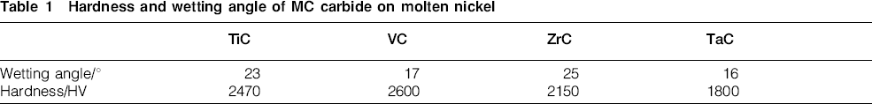
Tantalum (Ta) is an important refractory metal, which has been added to commercial Ni based superalloy to increase high temperature tensile strength and ductility as both a solid solution strengthening element and a MC carbide forming element.12 Different from Ti, Ta exhibits an excellent chemical inertness close to the noble metal.13 Therefore, it is easier to synthesise TaC carbide via the reaction between Ta and C in open environment to reinforce the laser clad coating. Hardness of TaC is higher than that of M7C3 carbide (1200–1600 HV). The hardness of the MC carbide and wetting angle between the MC carbide and molten nickel are listed in Table 1.10, 14, 15 As shown in Table 1, the hardness and wetting angle of TaC are the lowest. It is well known that the wear resistance of composite materials depends not only on the size, shape and hardness of the reinforcement but also on the bond strength between the reinforcement and matrix. The lower the wetting angle, the stronger the bond strength between the reinforcement and the matrix, and hence, the better the wear resistance. Although the hardness of TaC is relatively lower, TaC would have a stronger bond with nickel matrix than other MC carbides due to better wettability. Chao et al.16 fabricated in situ TaC particles in Ni based coating with Ta2O5 and pure C by laser cladding. In our previous work,17 Ta was used to refine the coarse carbide and reduce the crack susceptibility of the laser clad NiCrBSi coating. However, there is very little research on improving wear resistance of laser clad NiCrBSi coating by Ta element.
Hardness and wetting angle of MC carbide on molten nickel
In the present study, Ta is added to laser clad NiCrBSi coating to improve the wear resistance to sliding wear. The dry sliding wear behaviour and mechanism of the NiCrBSi+Ta composite coating and pure NiCrBSi coating are compared in order to investigate the influence of Ta on the wear resistance of the NiCrBSi coating. It is expected that laser clad Ta reinforced Ni based coating can be used in engineering to greatly improve wear resistance of component.
Experimental
Materials
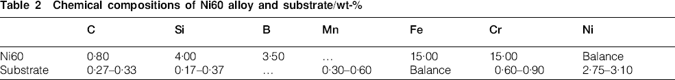
The powder mixture of the coating alloy was prepared from Ta (99·99% purity; 5 μm) powder and commercially available self-fluxing NiCrBSi alloy powder (Ni60) (50–150 μm), and blended sufficiently in a mortar. The substrate was medium carbon steel plate with the dimensions of 55×40×10 mm. The substrates were ground and cleaned with acetone before laser cladding. The chemical compositions of these materials are listed in Table 2. Different percentages of Ta powder (0 and 7 wt-%) were mixed with the Ni60 powder. Since Ta powder is much smaller and heavier than Ni60 powder, it is easy to sink to the bottom of the container. Therefore, the powders were mixed by a mixture of rosin and acetone. After that, the mixed powders were preplaced on the substrate surfaces to be dried in the ambient atmosphere. The thicknesses of the preplaced coatings were ∼1 mm.
Chemical compositions of Ni60 alloy and substrate/wt-%
Laser cladding
The cladding was conducted with an HJ-3000 3 kW continuous wave CO2 laser. The clad coatings were produced with the following optimum parameters: laser power of 1·7–2·2 kW, scanning speed of 300 mm min−1, spot diameter of 3 mm and overlapping of 30%. The sample's surfaces were protected by argon gas fed through coaxial nozzle at a flow rate of 10 L min−1.
Microstructure and chemical composition analysis
The samples were transversely sectioned, polished and chemically etched with a mixture of HCl/HNO3 = 1∶3. The microstructure was characterised by a VH-8000 optical microscope (OM) and an FEI Quanta 300 FEG scanning electron microscope (SEM). Chemical compositions were analysed by an energy dispersive spectrometer (EDS). The phase constitution was identified using X-ray diffraction (XRD; Rikagu D/Max-200; Cu source at 40 kV and 30 mA). Quantitative measurement of the phases was performed by image analysis. For each sample, three backscattered SEM images of the middle area of the coating were randomly chosen for the measurement.
Microhardness and fracture toughness tests
Microhardness profiles along the depth direction of the coatings measured by an MVC-1000A Vickers microhardness tester were tested under a load of 0·3 kg for 15 s.
Fracture toughness measurement was performed by means of indentation using the Vickers microhardness tester under a load of 1 kg within a dwelling time of 30 s. The radial cracks emanating from the corners of indentations were used to determine the fracture toughness Kc. In the present work, we utilised equation (1) to evaluate the fracture toughness18
Dry sliding wear test
Dry sliding wear test was carried out on an MPX-2000 pin on disc tribometer in air and at room temperature. The pin was made of the laser clad sample and machined to a cylinder of Φ5×18 mm. In order to avoid the effect of dilution from substrate, the coatings were made to form a thickness of ∼2 mm by means of multilayer laser cladding and acted as the wear faces. The surfaces of the coatings were ground to obtain a smooth surface with a roughness Ra of 0·6 μm. In the wear test, the pins were pressed against a stationary counterpart, a hardened and tempered GCr15 steel disc (62 HRC) with a roughness Ra of 0·6 μm, and rotated at a speed of 549 rev min−1. The radius of the rotation was 10 mm. The test loads were 30, 45, 60 and 75 N respectively. Each wear test lasted for 60 min. The average weight loss of three samples was taken under each load. Before and after each wear test, the sample and the counterpart were ultrasonically cleaned in ethanol. Wear mass loss was measured by an electronic balance with an accuracy of 0·1 mg. The volume loss is calculated by the wear weight and the density of the coating. The coating densities were measured by an electric hydrometer with an accuracy of 1 mg cm−3. Since the coatings were not porous, approximation as such was valid.
Results and discussion
Microstructure
Ta reinforced laser clad composite coating is free from pores. Figure 1 shows the optical micrographs of the cross-section of laser clad NiCrBSi coating (Fig. 1a) and Ni60+7 wt-%Ta composite coating (Fig. 1b). If the amount of dilution of the clad layer from the substrate is defined as the ratio of the maximum depth of the melted substrate to the sum of the maximum depth of the melted substrate and the maximum clad build-up, the amount of dilution of both coatings is <12%.
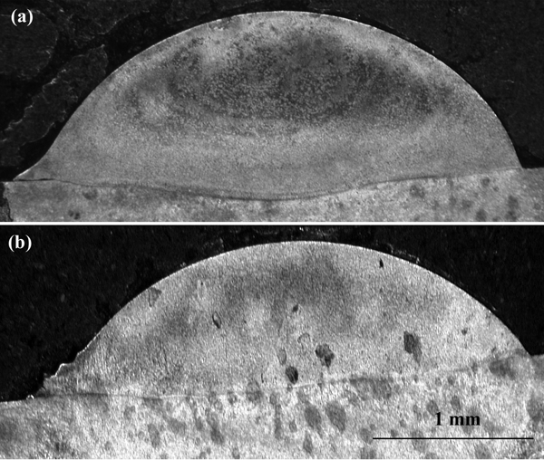
Optical micrographs of cross-section of laser clad a NiCrBSi and b Ni60+7 wt-%Ta coatings
The laser clad Ni60 coating is mainly composed of γ-Ni, M7C3, M23C6, Ni3B and CrB phases (Fig. 2a). The primary phases in the Ni60+7 wt-%Ta composite coating are γ-Ni, TaC and CrB and M23C6, and no M7C3 carbide is detected (Fig. 2b). As discussed in our previous work,17 after the addition of Ta, the growth of M7C3 carbide is suppressed.
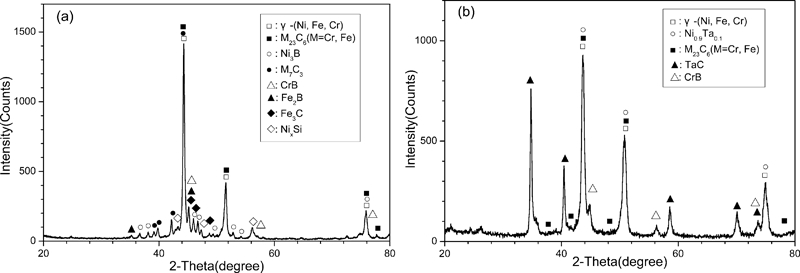
X-ray diffraction patterns of a Ni60 and b Ni60+7 wt-%Ta coatings
Figure 3a shows the SEM image of the Ni60 coating and Fig. 3b shows the magnified region A marked in Fig. 3a. The EDS analysis of the phases labelled in Fig. 3b is given in Table 3. From the XRD, EDS analysis and the previous researches,7, 19, 20 it can be easily determined that the cellular dendrite phase (S1), grey dendrite phase (S2) and black blocky phase (S3) are γ-Ni solid solution with Fe and Cr, M7C3 (M = Fe, Cr) and CrB respectively. The eutectics are γ-Ni+M23C6 and γ-Ni+Ni3B eutectic. As shown in Fig. 3, the coarse M7C3 carbide (about 40–180 μm long) has large aspect ratio, and the volume fraction of the eutectics is high.
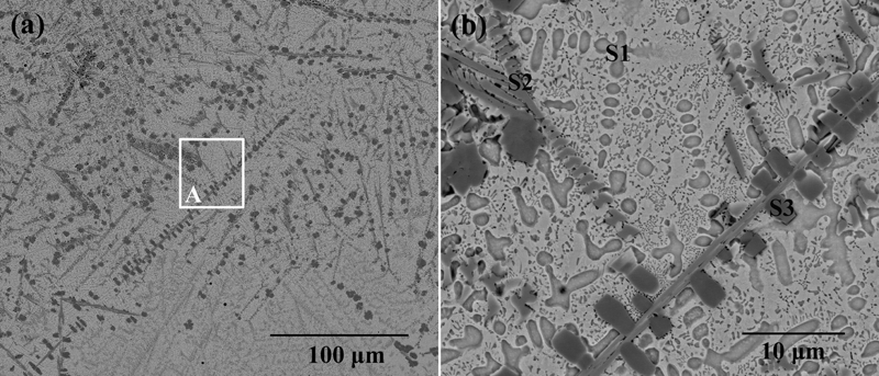
a SEM images (backscattered electron) of Ni60 coating and b high magnification of region A marked in a
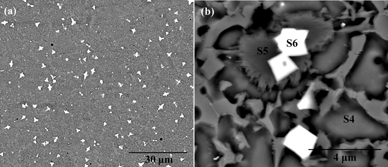
Energy dispersive spectroscopy analyses of Ni60 and Ni60+7 wt-%Ta coatings/wt-%
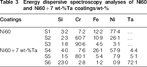
In the Ni60+7 wt-%Ta composite coating, in situ synthesised TaC particles (about 2–6 μm) are homogeneously distributed along with finer ones (<1 μm) dispersed thereamong (Fig. 4a). Different from the Ni60 coating, no coarse M7C3 dendrites are found in the composite coating. Acicular colonies form on the surfaces of some TaC particles (Fig. 4b). The compositions of the matrix (S4), colony (S5) and TaC (S6) phases in Fig. 4b are also listed in Table 3. The EDS result shows that Ta, Cr and Fe elements dissolve in the Ni matrix, and the colony has a high concentration of Cr. According to the analysis of EDS and XRD, it can be concluded that the colony is chromium boride or carbide. Li et al.21 found the similar colony structure, which consists of CrB laths, on the surfaces of TiC particles in the laser clad TiC reinforced NiCrBSi composite coating. In the Ni60+7 wt-%Ta composite coating, TaC first precipitates and grows up.17 Accompanying the precipitation of the TaC, the residual liquid around the TaC particle is enriched in chromium. Meanwhile, during rapid solidification, the high cooling rate develops a thermal gradient around the TaC particle due to large differences between the thermal properties of TaC and Ni based matrix, leading to the local undercooling in the vicinity of the TaC particles. When a sufficiently high undercooling is achieved, the acicular Cr rich boride or carbide will be nucleated and grow radically into the melt.21
Images (SEM) (backscattered electron) of morphologies of Ni60+7 wt-%Ta composite coating at a low magnification and b high magnification
Wang et al.22 reported that TiC carbide with a dendritic structure existed in laser clad coating. In the present work, however, it is interesting that all of the TaC particles are nearly equiaxed, and no TaC particles of dendritic shape are found.
Microhardness and fracture toughness
As shown in Fig. 5, the microhardness of the Ni60+7 wt-%Ta composite coating is lower than that of the Ni60 coating.
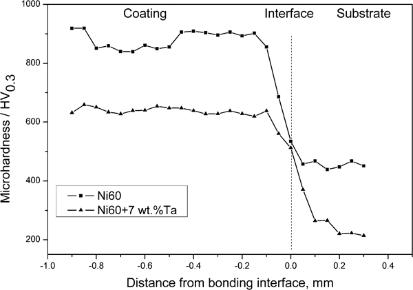
Cross-section microhardness profile of Ni60 and Ni60+7 wt-%Ta coatings
Because of the microstructural complexity of the laser clad coating, a number of hardness mechanisms are likely to be responsible for the changes in hardness. Lee and Gurland23 proposed a model to evaluate the hardness of WC–Co cemented carbides HC

Owing to high content of C, the Ni60 coating has a high volume fraction of γ-Ni+M23C6 eutectics and a relatively low volume fraction of the Ni matrix (∼17·8%). After the addition of Ta, the growth of γ-Ni+M23C6 eutectics is suppressed. As a result, the volume fraction of the Ni matrix increases up to ∼40·6%, leading to the decrease in the microhardness of the composite coating.
Figure 6 shows that only the indentation of the Ni60 coating (Fig. 6a) exhibits radial cracks, and no cracks are found at the corners of indentation of the Ni60+7 wt-%Ta composite coating (Fig. 6b), indicating that the composite coating has a higher fracture toughness as compared with the Ni60 coating. This is because Ta solid solution strengthens the Ni matrix and reduces the amount of the coarse carbides and brittle γ-Ni+M23C6 eutectics.
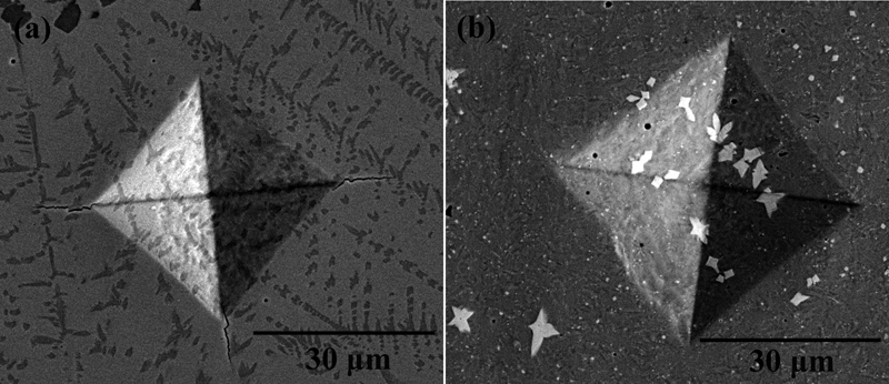
Vickers indentations on polished surfaces of a Ni60 and b Ni60+7 wt-%Ta coatings
Wear resistance
Figure 7 illustrates that the volume loss of the Ni60+7 wt-%Ta composite coating is much lower than that of the Ni60 coating under the same test conditions in the dry sliding wear test.
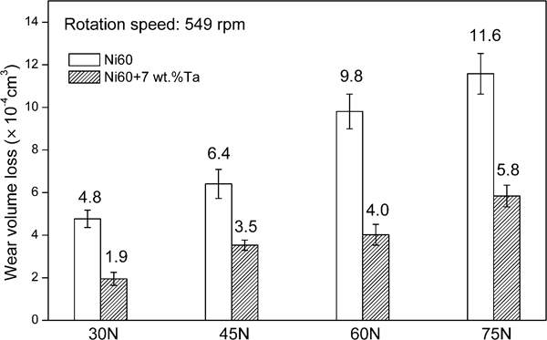
Volume loss of Ni60 and Ni60+7 wt-%Ta coatings as function of load under dry sliding wear condition
The worn surface of the Ni60 coating is characterised by craters and grooves parallel to the sliding direction (Fig. 8a) when tested under a load of 30 N. Since coarse particles with large aspect ratio tend to shatter at lower strains,24 the coarse carbides in the Ni60 coating are easily fractured and flake off from the coating, leading to the formation of the crater. Then, the spalls detached from the coating are trapped into the gaps between the sliding surfaces, ploughing the surfaces of the coating and the counterpart (Fig. 8b). The EDS analysis shows that the wear debris (S8 in Fig. 8b) on the surface of the counterpart has relatively high contents of Ni and Cr [68·4Fe–3·6O–8·2Cr–19·5Ni–0·3Mn (wt-%)], which indicates that this debris includes the spall detached from the coating. Therefore, the dominating wear mechanism of the Ni60 coating under a load of 30 N is abrasion and microflaking. In addition, the presence of O in the worn surface (S7 in Fig. 8a) [35·9Fe–0·8O–6·9Cr–53·2Ni–3·2Si (wt-%)] implies that oxidation plays a minor role.
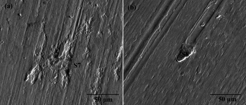
Images (SEM) of worn surface of a Ni60 coating and b counterpart after tested under load of 30 N
After tested under a load of 75 N, plastic deformation is observed on the surface of the Ni60 coating (Fig. 9a), showing the characteristic of adhesion wear. The high content of Ni in the large wear debris attached to the surface of the counterpart (S9 in Fig. 9b) [41·0Fe–2·6O–7·0Cr–47·4Ni–2·0Si (wt-%)] implies a transfer of material from the coating to the counterpart. Moreover, the high O content in the debris indicates that oxidation occurs during the wear process.
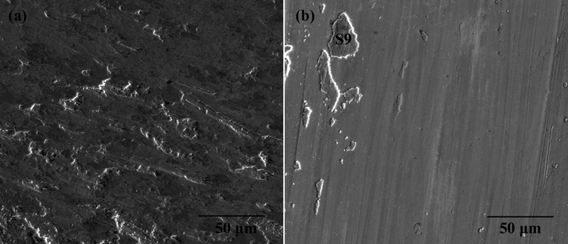
Worn surfaces of a Ni60 coating and b counterpart after tested under load of 75 N
There is a discontinuous oxide layer on the worn surface of the Ni60+7 wt-%Ta composite coating (Fig. 10a), when tested under a load of 30 N. A high Fe content in the oxide layer (S10 in Fig. 10a) [59·5Fe–4·0O–9·4Cr–23·3Ni–1·7Si–2·2Ta (wt-%)] indicates that the oxidised debris primarily originates from the counterpart. During the wear test, the worn surface of the composite coating can always be covered with an oxide layer under a low load (30 N) because the oxide layer can form faster than it is ploughed up by wear debris.
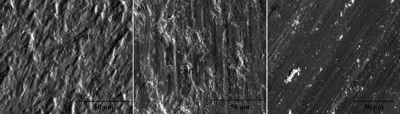
Worn surface of a Ni60+7 wt-%Ta composite coating tested under load of 30 N and b composite coating and c counterpart tested under load of 75 N
With an increase in normal load to 75 N, the area covered by the oxide layer decreases significantly, and the grooves on the worn surface become deeper (Fig. 10b). The reason is that, with the increase in load, the wear debris ploughs the coating surface more heavily, and thus the oxide layer wears up faster than it can form. Additionally, there is no obvious characteristic of adhesion on the worn surface. The content of Fe in the oxide layer (S11 in Fig. 10b) [75·2Fe–3·8O–6·2Cr–11·5Ni–1·0Si–2·3Ta (wt-%)] is very high, indicating that the oxide layer contains the oxidised debris transferred from the counterpart. The worn surface morphologies of the counterparts tested under different loads are similar, except that the counterpart tested under higher load has deeper scratches (Fig. 10c). Therefore, the primary wear mechanism of the composite coating is abrasion combined with the oxidation process under all test conditions.
In the wear process, the matrix is preferentially abraded, and then protruding TaC particles bear the applied load on the wear surface. It is interesting to note that a protruding TaC particle is still strongly bonded to the colony after tested under a load of 30 N (Fig. 11a), implying that the colony formed around the TaC particle is beneficial for the bond between the matrix and the TaC. In the case of 75 N load, it can be clearly observed that TaC particles resist the ploughing from the wear debris due to its high hardness, making the oxide remain on the downstream side of the TaC in the sliding direction (Fig. 11b). The oxide remnants on the worn surface can protect the worn surface from directly contacting with the counterpart. Under high contract stress, the TaC particles tend to be crushed, and then impressed into the matrix instead of being pulled out from the wear surface (Fig. 11c). The oxide remnants and TaC debris impressed into the worn surface will make a positive contribution to the wear resistance. In all of the above mentioned cases, no cracks are observed at the matrix/TaC interfaces or around the crushed TaC particles, indicating that the crack initiation and propagation are limited due to high fracture toughness of the composite coating and strong bond between the TaC particle and matrix.
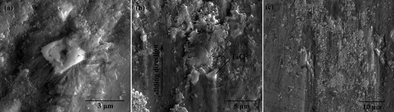
In situ TaC particles in wear surface of Ni60+7 wt-%Ta composite coating after tested under load of a 30 N and b, c 75 N
After the addition of Ta, the growth of the coarse M7C3 carbides is suppressed, and TaC particles are synthesised in the Ni60+7 wt-%Ta composite coating. TaC, with high hardness and strong atomic bonds, resists the microploughing, microcutting and repeated surface plastic deformation, and thereby, provides the composite coating a high resistance to abrasive and adhesive wear.
Conclusion
The dominating wear mechanism of the laser clad NiCrBSi (Ni60) coating under a low load (30 N) is abrasion and microflaking, and the oxidation plays a minor role. This is changed to adhesion and oxidation under a high load (75 N).
In the Ni60+7 wt-%Ta composite coating, in situ synthesised TaC particles are nearly equiaxed and homogeneously distributed. The colony that grows radially on the surfaces of the TaC particle is beneficial for cohesion strength between TaC particle and matrix.
Ta element increases the fracture toughness of the laser clad Ni60 coating and improves the abrasive and adhesive wear resistance to a much greater extent, making a good combination of toughness and wear resistance. This is attributed to the Ni matrix strengthened by Ta, nearly equiaxed TaC particles with high hardness and strong atomic bonds, strong bond between the TaC particle and matrix, the crushed TaC impressed into the matrix and the refinement of the coarse carbides with large aspect ratios. In dry sliding wear process, the main wear mechanism of the composite coating is abrasion combined with the oxidation process under all test conditions.
Footnotes
Acknowledgements
The authors thank the National Natural Science Foundation of China (grant no. 50675136 and no.50375096), the Applied Technology Development Foundation of Science and Technology Commission of Shanghai Municipality (grant no. 2010-110) and the Scholastic Foundation of Nanchang University (grant no. Z02887).