
Abstract
A layer of nickel–phosphorus alloy was electroless plated on the surface of microarc oxidised AZ31 magnesium alloy first, and then sealing treatment was performed on the electroless nickel plated coating using bis-(triethoxysilylpropyl)tetrasulphide silane. Fourier transform infrared spectroscopy, scanning electron microscope (SEM), energy dispersed X-ray spectroscope analyses, electrochemical techniques and immersion test were used for the analyses of surface morphology and structure and corrosion resistance of electroless nickel plated samples before and after sealing treatment. The results showed that the silane film by sealing treatment improves its corrosion resistance significantly.
Introduction
Magnesium alloys have been used widely in many industries, such as aerospace, automobile and electronics, due to their low density, high specific strength and specific stiffness of volume. However, magnesium alloys will encounter serious corrosion when putting them in moist atmosphere, neutral or acid solution containing chloride ion, etc., which limited their applications significantly.1 – 4 There are a lot of methods for preventing magnesium alloys from corrosion, such as chemical conversion, anodic oxidation and microarc oxidation, organic coating and metal plating, etc.2, 5 – 7
Microarc oxidation (MAO) on the surface of some metals, such as Ti, Al, Mg, and so on, has been paid more attention in recent years.8, 9 Although the MAO coating has a number of desirable properties, such as high bonding strength to the substrate, good wear resistance and corrosion resistance, its surface can be polluted to clean, and it is difficult to be cleaned completely. In addition, there are many micropores and microcracks on the MAO film due to the continual and intense sparking discharge and gas bubble on the surface of the sample,8 especially for magnesium alloys, which will reduce the corrosion resistance significantly. Recently, electroless nickel plated coating has been deposited on the surface of MAO coating,9 by which good corrosion resistance of MAO coating is combined with the advantages of the nickel plated coating. This coating has good wear resistance as well as a surface with characteristics of metallic and easy cleaning.
Electroless nickel plating is a technique that uses chemical method to get a protective coating on the material surface. The common process of electroless nickel plating is10 – 13 mechanical polishing→cleaning→sensitisation→activation→reduction→electroless plating→post-treatment. Although some information demonstrates that the nickel plated coating will have not macroscopic pores when its thickness reaches 15 μm,14 micropores are difficult to be avoided in the deposition process of Ni–P alloy.15, 16 It is well known that the standard electrode potential of nickel is higher than that of the substrate of magnesium alloy. The corrosion resistance of the electroless nickel plated coating is affected seriously by these micropores. Therefore, it must be performed to make sure that the nickel coating has no voids, or serious electrochemical corrosion will happen. In order to reduce the porosity of nickel plated coating and improve its corrosion resistance, sealing treatment to the electroless coating is needed.
With regard to the sealing treatment, many methods have been studied in recent years. Song et al.17 reported that the corrosion resistance of the electroless plated coating was improved by adding nanoparticles into the electroless plating solution. Sun et al.18, 19 reported that the corrosion resistance of the electroless plated coating was improved by sealing treatment of the coating using acrylic resin. Hou et al.20 and Zhu et al.21 used the sol–gel method for sealing treatment to electroless nickel plated coating. It is shown that the porosity of the electroless plated coating was reduced significantly, and its corrosion resistance was improved obviously.
In recent years, studies on the pretreatment of metals by silanes, aimed at replacing chromate based metal pretreatments for organic coating in corrosion protection, have attracted much attention due to its environment friendly nature.22 – 24 Silane coupling agent is a kind of material containing reactive groups in its molecular structure, which could combine with both inorganic and organic materials by chemical bonding. After preparation, a silane film with network structure can be formed on the surface of metals and other inorganic materials. However, there is no report on using of silane coupling agent to the sealing treatment of electroless plated coating directly. Among these silanes, bis-(triethoxysilylpropyl)tetrasulphide (BTESPT) silane was applied to the pretreatment of metal substrates first by van Ooij's group.25 It contains four S elements in its molecular structure, which have strong affinities for metals such as Zn, Cu, Ni, etc.25, 26 On the other hand, BTESPT silane film can be formed through condensation between –SiOH groups in the hydrolysed BTESPT. As a result, sealing treatment by BTESPT silane film could improve the corrosion protection to the substrate.
In this paper, the electroless plating process was used for the preparation of Ni–P coating on the surface of the microarc oxidation coating on AZ31 magnesium alloy without the common process of sensitisation. Then, a layer of BTESPT silane film was formed on the surface of the nickel plated coating. Fourier transform infrared spectroscopy (FTIR), SEM, energy dispersed X-ray spectroscopy and electrochemical tests were used for the analyses of surface morphology and structure and corrosion behaviour of the coating.
Experimental
The substrate material used was AZ31 magnesium alloy with microarc oxidised (MAO) film. At first, the sample was cleaned in acetone with ultrasonic for 5 min. Then, the sample was immersed into the silane solution for 3 min and oven cured at 100°C for 30 min. After that, the process of electroless composite plating consisted of activation (0·2 g L−1 PdCl2.2H2O, 10 mL L−1 HCl, room temperature, 1 min), reduction (2%NaH2PO2.H2O, room temperature, 10 min) and electroless Ni–P plating for 60 min. The compositions and operation conditions of electroless Ni–P plating were as follows: NiSO4.6H2O, 25 g L−1; NaH2PO2.H2O, 23 g L−1; Na3C6H5O7.2H2O, 20 g L−1; buffer agent, 24 g L−1; pH = 8·0; and T = 75°C.
After electroless nickel–phosphorus plating, the samples were first immersed into the hydroalcoholic solution of BTESPT for 5 min at room temperature and then oven was cured at 120°C for 1 h. The composition of hydroalcoholic solution of BTESPT is BTESPT/distilled water/alcohol (v/v/v) = 5∶5∶90, and the silane solution was kept for 72 h for hydrolysis at room temperature before use.
A Nicolet spectrometer (Nicolet Nexus 670) was used to record the FTIR reflection spectra on AZ31 specimens. Sixty-four scans were collected for each measurement over the spectral range of 500–4000 cm−1 with a resolution of 2 cm−1. Scanning electron microscopy (Serion 200 and Quanta-200) was performed to observe the surface morphology of the samples with an accelerating voltage of 20 kV. Energy dispersive X-ray (Genesis 60s) analysis was used for the surface chemical compositions. The corrosion behaviour was characterised by electrochemical and immersion tests at room temperature in 3·5 wt-%NaCl solution. Electrochemical impedance spectra (EIS) and polarisation measurements were carried out using CHI660C at the open circuit corrosion potential. A three-electrode electrochemical cell, consisting of the working electrode (∼1 cm2 exposed area), saturated calomel electrode (SCE) as reference electrode and stainless steel as counter electrode, was adopted to evaluate the protective performance in the aggressive solution of 3·5 wt-%NaCl. The measuring frequency ranged from 105 Hz down to 10−2 Hz. The employed amplitude of sinusoidal signal was 10 mV. The EIS raw data were analysed using ZView. Polarisation curve measurements were carried out in the potential range from −2·0 to 0·4 V(SCE), and a scan rate of 2 mV s−1 was applied.
Results and discussion
Surface morphology and structure analysis before immersion test
Figure 1a shows surface images of the electroless nickel plated coating on the surface of microarc oxidated AZ31 magnesium alloy. It can be seen that the electroless Ni–P coating is comprised of cauliflower-like nodules. Table 1 shows the composition of region A in Fig. 1a. It can be seen that the coating is mainly composed of P (6·35 wt-%) and Ni (92·75 wt-%). Figure 1b shows the SEM images of the cross-section of the coating after electroless nickel plating of the sample. It can be measured that the thickness of the Ni–P coating is ∼19 μm. Figure 1c shows line scanning of the elements from the nickel plated coating to substrate of AZ31 magnesium alloy. A surface layer of Ni–P coating, containing mainly Ni and P and with a thickness of ∼20 μm, can be observed. Beneath this layer, a layer of the MAO coating containing mainly Mg and O and with a thickness of ∼9 μm can be observed. Figure 2 shows the surface images of the sealing treated sample of electroless nickel plated coating by BTESPT. It can be seen that its surface morphology is similar to that of the nickel plated coating shown in Fig. 1a. The composition of region B in Fig. 2 is given in Table 1. It can be seen further that after sealing treatment by BTESPT, elements of C, Si and S appear on the surface of the sample, which are the unique elements of silane, indicating that the silane film is covered on the surface of the nickel plated coating.
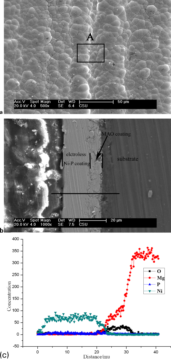
Images (SEM) of electroless Ni–P plated sample:
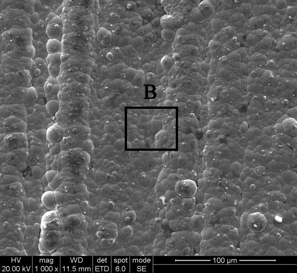
Image (SEM) of sealing treated sample by BTESPT
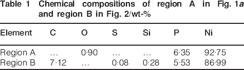
Figure 3 shows the FTIR spectrum of the sealing treated sample before immersion test. The bond at 3311 cm−1 could be ascribed to the free –OH peak in the silane film. The peaks at 2970, 1439 and 1299 cm−1 can be ascribed to CH2 in Si–O–CH2CH3 group. The peak at 2920 cm−1 could be assigned to CH3 in Si–O–CH2CH3 group. The peak at 1240 cm−1 could be attributed to CH2 in –CH2–S– group. The band at 1081 cm−1 could be ascribed to Si–O–Si and Si–O–C. The bond at 952 cm−1 could be ascribed to Si–O–C. The groups corresponding to these absorption peaks coincide with the molecular structure of BTESPT completely, indicating that the silane film has already covered the surface of the nickel plated coating.
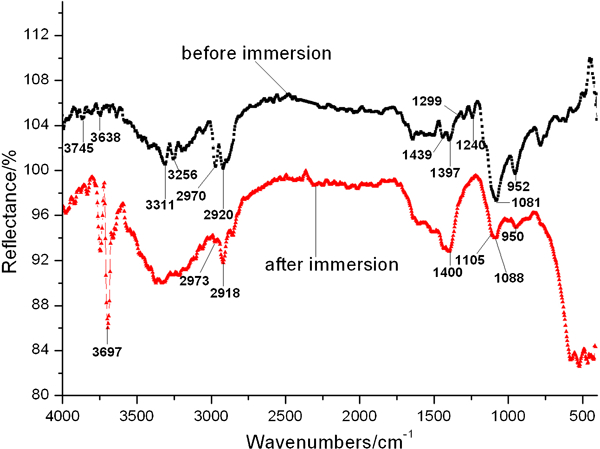
Spectra (FTIR) of sample sealed by BTESPT film before and after immersion test
Surface morphology and structure analysis after immersion test
Figure 4 presents the macroscopic surface morphologies of the electroless nickel plated sample and the sealing treated sample after different times of immersion. For the electroless nickel plated sample without sealing treatment, the electroless plated Ni–P coating can protect the substrate very well at the initial stage of immersion, and any changes cannot be observed on its surface. However, when the sample was immersed at ∼6 h, several air bubbles appeared on its surface. After 7 h immersion, a corrosion region can be observed. When immersion prolongs to 24 h, a large corrosion region can be observed. As for the sample after sealing treatment, its surface does not have an obvious change at the first 48 h of immersion. After 72 h immersion, a corrosion pit can be observed on its surface. The result of immersion test indicates that sealing treatment using BTESPT silane can improve the corrosion resistance of electroless plated Ni–P coating obviously, which coincided with the results of polarisation and EIS.
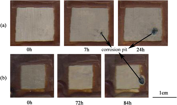
Surface morphologies of a electroless Ni–P plated sample and b sealing treated sample after different immersion times
Figure 5 shows the SEM images of the surface of the sealing treated sample after immersion. It can be seen that much corrosion products covered its surface. Figure 3 shows the FTIR spectrum of the sealing treated sample after immersion. The peak at 3697 cm−1 could be ascribed to the –OH of corrosion products [Mg(OH)2].27 The appearance of strong bonds at 2973, 2918, 1400 and 1088 cm−1 suggested that the silane film still exists on the surface of the nickel plated coating after a long time immersion. After immersion, the peaks at 2970, 2920, 1088 and 950 cm−1 become weak, and the peak ∼1400 cm−1 ascribed to –CH2–S– becomes strong, indicating that thinning and dissolution of the silane film occurred during immersion.
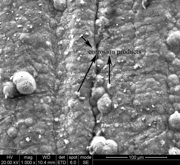
Image (SEM) of sample sealed by BTESPT after immersion test
Electrochemical analysis
Figure 6 shows the polarisation curves of the samples with different surface coatings. The fitted results of polarisation curves are listed in Table 2. As we can see, the corrosion current density of the sample with MAO coating is about one order of magnitude lower than that of the sample with electroless nickel plated coating on it. The reason for the MAO sample having a lower corrosion current is that its surface is a layer of oxidised film (MgO and Mg2SiO4), which has a higher polarisation resistance (RP). The corrosion current density of the sample after sealing treatment by BTESPT is a little lower than that of the sample without sealing treatment. It should be noted that the corrosion potential of the sample with electroless plated Ni–P coating is 1300mV higher than that of the sample with MAO coating, indicating that the corrosion potential of MAO sample can be promoted obviously by electroless nickel plating. The curve shape of the sealing treated sample is similar to that of the nickel plated sample without sealing treatment, indicating that the silane film may only act as a physical barrier and improve the corrosion resistance through reducing the Cl− ion reached at the interface, without changing the electrode reaction dynamics of the electroless plated surface.24, 28 The BTESPT silane film on the surface of the nickel plated coating is in a state of network through condensation of the hydrolysed –SiOH groups and is link aged to nickel plated coating by Ni–S bonds due to the strong affinity of S element in the molecular structure of BTESPT to Ni.25, 26 On the other hand, sealing treatment by the silane film reduces the porosity of the nickel plated coating by penetration of the hydrolysed BTESPT into the micropores existing in the nickel plated coating.
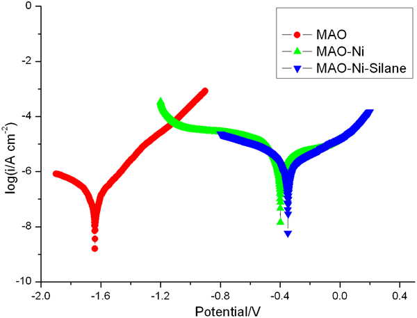
Polarisation curves of samples with different coatings
Fitted results of polarisation curves for different samples
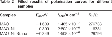
Figure 7 shows the EIS (Bode curves and Nyquist curves) of the sample with electroless plated Ni–P coating after different times of immersion. The EIS at 0·5 and 3·5 h contain two time constants. The capacitive loop at high frequency (102–104 Hz) is attributed to the barrier effect of the nickel plated coating, and the capacitive loop at low frequency (1–10 Hz) is associated with the charge transfer at the interface between nickel plated coating and MAO coating.24, 28 – 31 At the initial stage of immersion (0–3·5 h), the maximum value and the peak width of the phase angle are large, which indicates that the nickel plated coating has a good protective capability to the substrate. After 7 h of immersion, there is only one obvious time constant in Bode curves. At this stage, the sample underwent serious corrosion at one region, as shown in Fig. 4. It is known that there are some micropores in the nickel plated coating. Moreover, there are microcracks in the MAO coating, or the compact layer of the MAO coating is very thin in some places. After 7 h of immersion, the NaCl solution reached at the substrate through these defects and the nickel plated coating and MAO coating lost their protective function to the substrate, and the corrosion of the substrate of AZ31 magnesium alloy dominated almost the whole corrosion process and had little relation to the nickel plated coating and MAO coating.
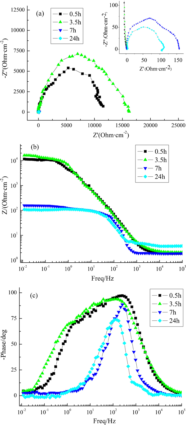
Plots (EIS) of sample with electroless plated Ni–P coating:
The equivalent circuit model can be described as Rs(RC). At high frequency, the capacity (C) has a low resistance, and the whole resistance is decided by the electrolyte resistance (Rs). Its phase angle is close to zero. At low frequency, C has a large resistance, and the whole resistance is decided by Rs+R. Its phase angle is also close to zero.32
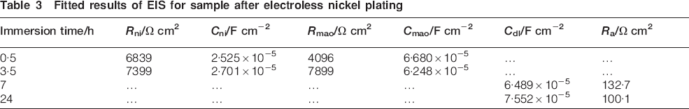
Figure 8 shows the equivalent circuit models for impedance spectra in Fig. 7, in which Rs is the resistance of electrolyte solution, Cni and Rni are the capacitor and resistance of the nickel plated coating and Cmao and Rmao are the capacitor and resistance of the MAO coating. Cdl is the capacitor of corrosion products on the surface of the substrate, and Ra indicates the property of the substrate magnesium alloy. The fitted results are listed in Table 3.
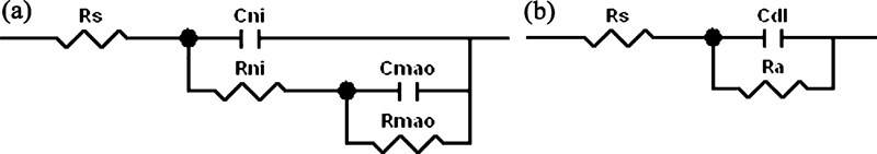
Equivalent circuit models for impedance spectra:
Fitted results of EIS for sample after electroless nickel plating
In order to improve the corrosion resistance of the nickel plated coating, the effect of these micropores in the nickel plated coating must be reduced. The immersion test and the following EIS result demonstrate that sealing treatment of the nickel plated coating by BTESPT silane can meet this requirement.
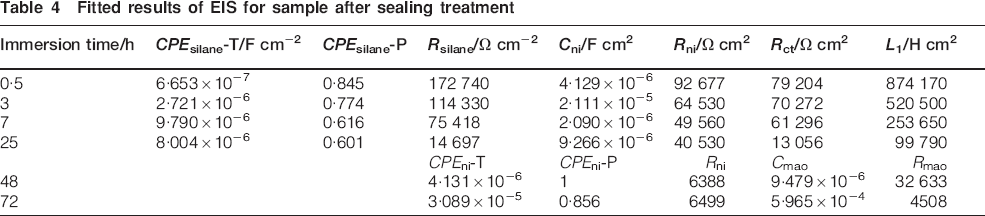
Figure 9 shows the EIS (Bode curves and Nyquist curves) of the sealing treated sample after different times of immersion. It can be seen that at 0·5 h immersion, the impedance at low frequency is one order of magnitude higher than that in Fig. 7, which can be ascribed to the sealing treatment of the plated Ni–P coating by BTESPT silane. As for 0·5–25 h immersion, inductive loop can be observed at low frequency, which may be attributed to the correlation between nickel plated coating and the silane film. The NaCl solution reached at the surface of the Ni–P coating through micropores existed in the silane film and corroded the Ni–P coating. On the other hand, S in the silane film might have some interactions with Ni in the plated coating. There is a capacitive loop at high frequency (104–105 Hz), which can be ascribed to the silane film. Another capacitive loop, at a broad frequency (about 100–104 Hz), can be ascribed to the sealed Ni–P coating. The equivalent circuit model for the earlier stage (0·5–25 h) is established as shown in Fig. 10a, in which Rs is the resistance of the electrolyte solution, CPEsilane and Rsilane represent the capacitor and resistance of the silane film and CPEni and Rni are capacitor and resistance of the electroless nickel plated coating. The series of inductance component (L1) and Rct indicates corrosion reactions on the surface of the MAO coating and absorption of corrosion products.27 After 48 h immersion, both the inductive loop at low frequency and the capacitive loop at high frequency (104–105 Hz) due to the silane film disappear. The spectra are very similar to that of the obtained peaks at 0·5 and 3·5 h shown in Fig. 7. This suggests that the destruction of the silane film was complete after 48 h immersion and that the electrolyte solution got in touch with the nickel plated coating directly in the destroyed regions. The equivalent circuit model for the later stage is shown in Fig. 10b. CPEni and Rni are the capacitance and resistance of the nickel plated coating, and Cmao and Rmao are capacitance and resistance of the MAO coating. The equivalent circuit models fit the spectra well. Table 4 shows the fitted results. It can be seen that Rsilane of the silane film declines obviously during the earlier stage; however, it is still above 104 Ω•cm2 at 25 h immersion. In addition, Rni of the Ni–P coating is promoted greatly until 25 h immersion as compared to that in Table 3, which could be ascribed to the sealing effect of the micropores in the Ni–P coating by silane. These indicate that the corrosion resistance of the nickel plated coating on MAO coating of magnesium alloy can be improved obviously by sealing treatment of BTESPT silane.
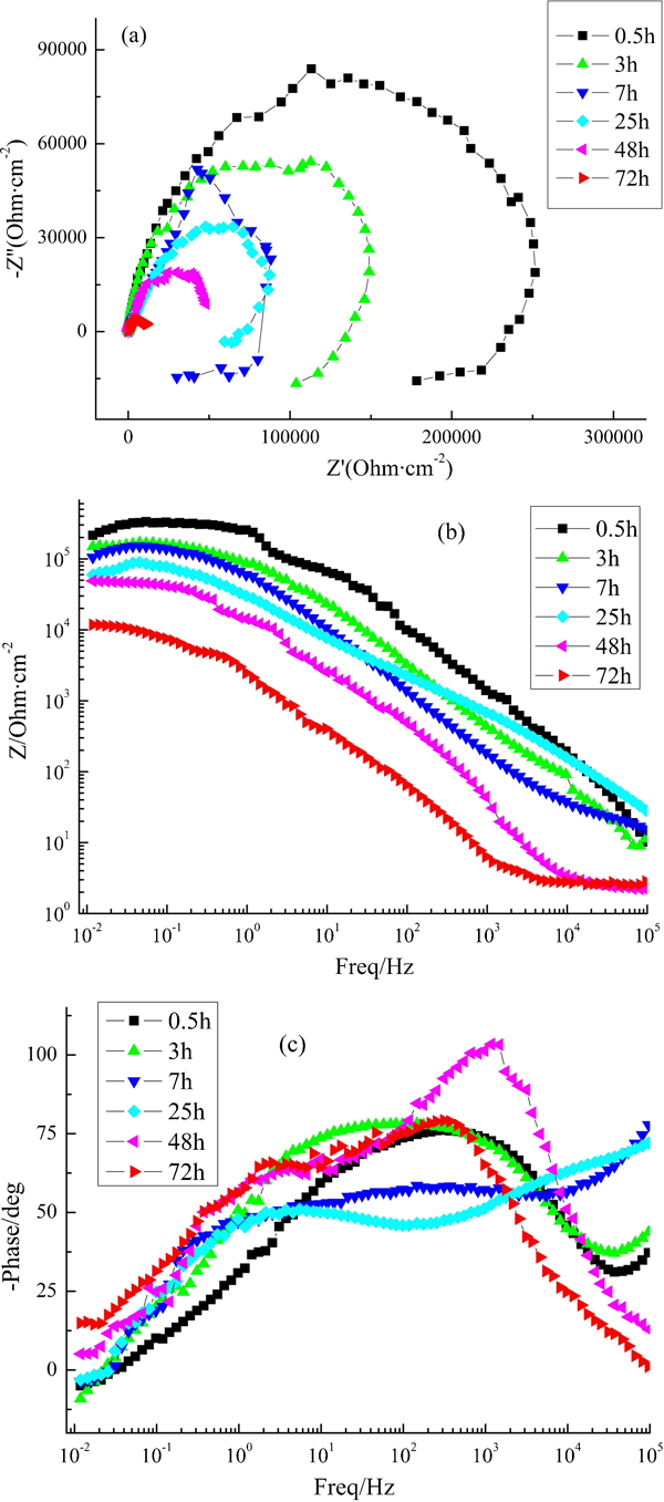
Plots (EIS) of sample with sealing treated electroless Ni–P plated coating:
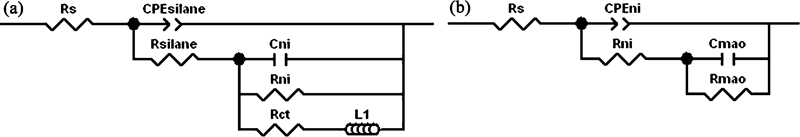
Equivalent circuit models for impedance spectra in Fig. 9:
Fitted results of EIS for sample after sealing treatment
Conclusion
The Ni–P coating was electroless plated on the surface of MAO AZ31 magnesium alloy without the common process of sensitisation to the MAO coating. The corrosion potential is shifted from −1·639 to −0·399 V.
The corrosion resistance of Ni–P coating plated electroless on the surface of MAO AZ31 magnesium alloy can be improved greatly by sealing treatment of BTESPT silane. At the initial stage, the impedance at low frequency for the sealed sample is one order of magnitude higher than that of the sample without sealing treatment. This can be ascribed mainly to the physical barrier effect of the silane film formed on the nickel plated coating.
For the sealed sample, Rni of the nickel plated coating is promoted greatly, and after 72 h of immersion, the impedance at low frequency is kept at 104 Ω cm2. These are mainly due to the sealing effect of the micropores in the nickel plated coating by silane.